Rotational Dynamics and Torque
2. Rotational Equilibrium
Learning outcomes
- I can define rotational equilibrium.
- I can calculate net torque on an object.
- I can determine conditions for equilibrium.
- I can analyze balanced rotational systems.
- I can solve static equilibrium problems.
- .
- Examples for rods, disks, and spheres.
Rotational Equilibrium
An object is in rotational equilibrium when the combined turning effect of all forces acting on it is zero.
The turning effect of a force is called torque.
For rotational equilibrium:
Στ = 0
This means that the total clockwise torque and total counterclockwise torque balance each other.
An object in rotational equilibrium has:
α = 0
so its angular velocity does not change.
A stationary beam, balanced seesaw, hanging sign, ladder, bridge, or shelf can all provide examples of rotational equilibrium.


Torque
Torque measures the ability of a force to cause rotation about a pivot or axis.
It depends on:
- the magnitude of the force
- the distance from the pivot
- the angle at which the force acts
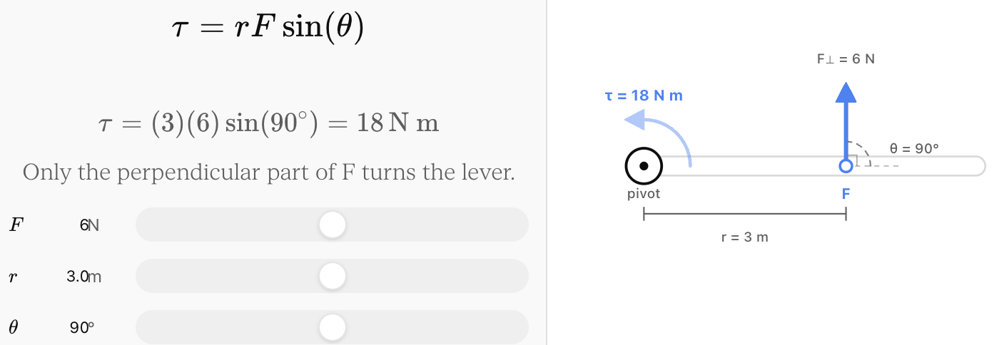
where:
- τ = torque
- r = distance from pivot to where the force is applied
- F = force
- θ = angle between r and F
The SI unit of torque is:
newton metre (N·m)
Perpendicular Forces
Torque is greatest when the force acts perpendicular to the lever arm.
If:
θ = 90°
then:
sin 90° = 1
so:
τ = rF
This simpler form is used in many equilibrium problems.
Worked Example: Simple Torque
A force of:
F = 30 N
acts perpendicular to a wrench:
r = 0.40 m
from the pivot.
Torque:
τ = rF
τ = (0.40)(30)
τ = 12 N·m
Why Distance from the Pivot Matters
A force applied farther from the pivot produces more torque.
Suppose the same 20 N force is applied at different distances:
| Distance from Pivot | Force | Torque |
|---|---|---|
| 0.10 m | 20 N | 2 N·m |
| 0.20 m | 20 N | 4 N·m |
| 0.50 m | 20 N | 10 N·m |
| 1.00 m | 20 N | 20 N·m |
For a perpendicular force:
τ ∝ r
This is why:
- door handles are placed far from hinges
- long wrenches make bolts easier to turn
- long crowbars provide greater turning effect


Why Force Direction Matters
Not all of a force contributes to rotation.
Only the component of force perpendicular to the lever arm produces torque.
If the force acts directly toward or away from the pivot:
θ = 0° or 180°
and:
sin θ = 0
Therefore:
τ = 0
A large force can produce zero torque if its line of action passes through the pivot.
Worked Example: Force at an Angle
A 50 N force is applied:
0.60 m
from a pivot at an angle of:
30°
to the lever arm.
Torque:
τ = rF sin θ
τ = (0.60)(50)(sin 30°)
τ = (0.60)(50)(0.50)
τ = 15 N·m
If the same force were perpendicular:
τ = (0.60)(50)
τ = 30 N·m
Changing the direction of the force changed its turning effect.
The Moment Arm
Another way to calculate torque uses the perpendicular distance between the pivot and the force's line of action.
If this perpendicular distance is d:
τ = Fd
where d is sometimes called the:
- moment arm
- torque arm
- perpendicular lever arm


This method is especially useful in static equilibrium diagrams.
Direction of Torque
Torque has a rotational direction.
A common sign convention is:
counterclockwise torque = positive
clockwise torque = negative
For example:
τ₁ = +20 N·m
τ₂ = −12 N·m
Then:
Στ = 20 − 12
Στ = +8 N·m
The net torque is counterclockwise.
Net Torque
When several forces act on an object, calculate the torque produced by each force and then add them with their signs.
Στ = τ₁ + τ₂ + τ₃ + ...
If:
Στ ≠ 0
the object has a net rotational effect.
If:
Στ = 0
the object is in rotational equilibrium.
Worked Example: Two Torques
A beam experiences:
- +18 N·m counterclockwise
- −18 N·m clockwise
Then:
Στ = +18 − 18
Στ = 0
Therefore, the beam is in rotational equilibrium.
The Principle of Moments
For an object in rotational equilibrium:
total clockwise torque = total counterclockwise torque
For perpendicular forces:
F₁r₁ = F₂r₂
This relationship is often called the principle of moments.


Worked Example: Balanced Seesaw
A child weighing:
300 N
sits:
2.0 m
from the pivot.
Another child weighs:
400 N
How far from the pivot should the second child sit to balance the seesaw?
For equilibrium:
clockwise torque = counterclockwise torque
(300)(2.0) = (400)r
600 = 400r
r = 1.5 m
Therefore, the second child should sit:
1.5 m from the pivot
on the opposite side.
A Smaller Force Can Balance a Larger Force
Rotational equilibrium does not require equal forces.
Consider:
F₁ = 600 N at 1.0 m
F₂ = 300 N at 2.0 m
Torque from F₁:
τ₁ = (600)(1.0)
= 600 N·m
Torque from F₂:
τ₂ = (300)(2.0)
= 600 N·m
The torques are equal even though the forces are not.
This is the basic principle behind levers.
Rotational Equilibrium Does Not Necessarily Mean Stationary
If:
Στ = 0
then:
α = 0
This means angular velocity is constant.
The object could be:
- stationary
- rotating at constant angular velocity
For static equilibrium, however, the object is stationary.
Therefore, static equilibrium is a special case of equilibrium.
Translational Equilibrium
For an object to remain completely stationary, balancing torques is not enough.
The forces must also balance.
For translational equilibrium:
ΣF = 0
For rotational equilibrium:
Στ = 0
For complete static equilibrium:
ΣF = 0
and:
Στ = 0


Two Conditions for Static Equilibrium
A stationary object must satisfy both conditions.
Force equilibrium
ΣF_x = 0
ΣF_y = 0
Torque equilibrium
Στ = 0
If either condition fails, the object will not remain in static equilibrium.
Balanced Forces Do Not Guarantee Balanced Torques
Suppose two equal forces act in opposite directions.
Their net force may be zero.
However, if they act at different positions, they can produce rotation.
Therefore:
ΣF = 0 does not automatically mean Στ = 0
Both conditions must be checked.
Balanced Torques Do Not Guarantee Balanced Forces
The reverse is also true.
An object might have:
Στ = 0
but:
ΣF ≠ 0
It would not rotate faster, but it could accelerate linearly.
Again, complete static equilibrium requires:
ΣF = 0 and Στ = 0
Choosing a Pivot
One of the most useful strategies in equilibrium problems is choosing a convenient pivot.
Any point can be used to calculate torque when an object is in static equilibrium.
However, the best choice is often a point where an unknown force acts.
Why?
Because that force then has:
r = 0
and therefore produces:
zero torque
This can eliminate an unknown from the torque equation.
Support Forces
Beams, bridges, shelves, and platforms are often supported at one or more locations.
The supports exert forces called reaction forces.
For example, a horizontal beam supported at both ends may experience:
- its own weight
- an additional load
- upward reaction at the left support
- upward reaction at the right support
Static equilibrium allows the support forces to be calculated.


Worked Example: Beam with a Central Load
A 4.0 m beam has negligible mass.
A:
600 N
load is placed at its centre.
The beam is supported at both ends.
Let the upward support forces be:
F_L and F_R
Because the load is exactly in the centre, symmetry tells us:
F_L = F_R
Vertical equilibrium:
F_L + F_R = 600
Therefore:
F_L = 300 N
F_R = 300 N
Solving the Same Problem Using Torque
Choose the left support as the pivot.
The left support force produces zero torque.
Taking counterclockwise as positive:
(F_R)(4.0) − (600)(2.0) = 0
4F_R = 1200
F_R = 300 N
Now use:
ΣF_y = 0
F_L + 300 − 600 = 0
F_L = 300 N
This demonstrates how force and torque equations work together.
Off-Centre Load
Now suppose a massless 4.0 m beam carries a:
600 N
load only:
1.0 m
from the left support.
Let the support forces again be F_L and F_R.
Choose the left support as the pivot.
Torque equilibrium:
(F_R)(4.0) − (600)(1.0) = 0
4F_R = 600
F_R = 150 N
Vertical force equilibrium:
F_L + 150 − 600 = 0
F_L = 450 N
The support closer to the load carries more of the force.
The Weight of the Beam
Real beams have mass.
For a uniform beam, its weight acts through its:
centre of mass
For a uniform beam of length L, the centre of mass is:
L/2
from either end.


Worked Example: Uniform Beam
A uniform horizontal beam is:
6.0 m long
and weighs:
300 N
It is supported at both ends.
Because the beam is uniform, its weight acts at the centre:
3.0 m from either end
By symmetry:
F_L = F_R
Vertical equilibrium:
F_L + F_R = 300
Therefore:
F_L = F_R = 150 N
Beam with Its Own Weight and an Additional Load
A uniform 6.0 m beam weighs:
200 N
A:
400 N
load is placed:
1.5 m
from the left support.
Find the support forces.
Let:
F_L = left reaction
F_R = right reaction
The beam's weight acts at:
3.0 m
from the left end.
Choose the left support as the pivot.
Torque equilibrium:
(F_R)(6.0) − (400)(1.5) − (200)(3.0) = 0
6F_R − 600 − 600 = 0
6F_R = 1200
F_R = 200 N
Now use vertical equilibrium:
F_L + F_R − 400 − 200 = 0
F_L + 200 = 600
F_L = 400 N
Check:
Total upward force = 400 + 200 = 600 N
Total downward force = 400 + 200 = 600 N
The forces balance.
Checking the Torques
Using the left support as pivot:
Counterclockwise torque:
(200)(6.0) = 1200 N·m
Clockwise torques:
(400)(1.5) + (200)(3.0)
= 600 + 600
= 1200 N·m
Therefore:
Στ = 0
Both equilibrium conditions are satisfied.
Hanging Signs
A sign attached to a wall by a horizontal beam provides another common static-equilibrium problem.
The sign's weight tends to rotate the beam downward.
A cable or support force provides an opposing torque.


The torque produced by the cable depends on:
- tension
- distance from hinge
- angle of the cable
For an angled force:
τ = rF sin θ
Worked Example: Cable Supporting a Beam
A horizontal beam extends:
2.0 m
from a wall.
A sign weighing:
300 N
hangs at the end.
A cable attached at the end of the beam makes an angle of:
30°
with the beam.
Ignore the beam's mass.
The sign produces clockwise torque:
τ_sign = (2.0)(300)
τ_sign = 600 N·m
The cable tension T produces counterclockwise torque:
τ_T = (2.0)T sin 30°
For equilibrium:
(2.0)T(0.50) = 600
T = 600 N
Therefore:
cable tension = 600 N
Why Only the Perpendicular Component Matters
In the previous example, the cable tension has:
- a component parallel to the beam
- a component perpendicular to the beam
Only the perpendicular component produces torque around the hinge.
The perpendicular component is:
F_perpendicular = F sin θ
Therefore:
τ = rF_perpendicular
This is equivalent to:
τ = rF sin θ
Ladders and Static Equilibrium
A ladder leaning against a wall can also be analyzed using equilibrium.
Possible forces include:
- weight of the ladder
- weight of a person
- normal force from the floor
- normal force from the wall
- friction from the floor


A free-body diagram is particularly important for these problems.
Centre of Mass and Stability
The position of the centre of mass affects rotational equilibrium.
The weight of an object can be treated as acting through its centre of mass.
If the vertical line through the centre of mass lies inside the object's base of support, the object can usually remain stable.
If that line moves outside the base, gravity produces a torque that tends to tip the object.


Tipping
Consider a tall cabinet.
As it tilts, its centre of mass moves sideways relative to the base.
As long as the line of action of its weight falls within the base:
the gravitational torque tends to restore the object.
Once the line of action moves beyond the edge:
gravity produces a torque that causes the object to tip.
This explains why:
- wide objects are generally more stable
- objects with low centres of mass are generally more stable
Torque and the Centre of Mass
Suppose an object's weight is:
W = mg
If the perpendicular distance from its line of action to a pivot is d:
τ_weight = Wd
or:
τ_weight = mgd
This torque can cause an object to tip or rotate unless another torque balances it.
Balancing Several Forces
Some equilibrium problems involve more than two torques.
Suppose a beam experiences:
- 20 N downward at 1 m left of the pivot
- 40 N downward at 2 m right of the pivot
- an unknown downward force F at 3 m left of the pivot
Take counterclockwise as positive.
Left-side downward forces produce counterclockwise torque.
Right-side downward forces produce clockwise torque.
Torque equilibrium:
(20)(1) + F(3) − (40)(2) = 0
20 + 3F − 80 = 0
3F = 60
F = 20 N
Static Equilibrium Problem-Solving Strategy
A reliable method is:
Draw a free-body diagram.
Show every external force.
Choose positive directions.
For example:
- upward positive
- right positive
- counterclockwise torque positive
Choose a convenient pivot.
Try to choose a pivot where an unknown force acts.
Calculate perpendicular distances.
Torque depends on the perpendicular distance to the force's line of action.
Apply rotational equilibrium.
Στ = 0
Apply translational equilibrium.
ΣF_x = 0
ΣF_y = 0
Solve the equations.
Finally, check whether the forces and torques actually balance.
Example: Person Standing on a Diving Board
A 4.0 m diving board has negligible mass and is supported at both ends of a 1.0 m support region.
Suppose a person weighing:
600 N
stands at the far end, 4.0 m from the left support.
Let the right support be 1.0 m from the left support.
Take torques about the left support.
The person's clockwise torque is:
τ_person = (600)(4.0)
= 2400 N·m
The right support must provide:
F_R(1.0) = 2400
Therefore:
F_R = 2400 N upward
Now use vertical force equilibrium:
F_L + 2400 − 600 = 0
F_L = −1800 N
The negative answer means the left support force acts:
downward
with magnitude:
1800 N
This is physically possible if the board is securely attached to the support.
A negative result often tells us that our assumed force direction was opposite to the actual direction.
Equilibrium and Newton's Laws
Rotational equilibrium is closely connected to Newton's laws.
For linear motion:
ΣF = ma
If:
ΣF = 0
then:
a = 0
For rotational motion:
Στ = Iα
If:
Στ = 0
then:
α = 0
The parallel is:
| Linear Motion | Rotational Motion |
|---|---|
| Force F | Torque τ |
| Mass m | Moment of inertia I |
| Linear acceleration a | Angular acceleration α |
| ΣF = ma | Στ = Iα |
| ΣF = 0 → a = 0 | Στ = 0 → α = 0 |
Balanced Rotational Systems
Many everyday structures depend on rotational equilibrium.
Examples include:
- shelves
- cranes
- bridges
- signs
- seesaws
- diving boards
- ladders
- human limbs
- balances and scales
Engineers must ensure that both forces and torques remain within safe limits.
Human Body Example
The human body also contains lever systems.
When holding an object in the hand, muscles can produce forces much larger than the object's weight because the muscle often acts very close to the joint.
For example, if a 50 N object is held:
0.30 m
from the elbow, its torque is:
τ = (50)(0.30)
τ = 15 N·m
If the muscle's effective moment arm is only:
0.030 m
then, ignoring other forces:
F_muscle(0.030) = 15
F_muscle = 500 N
The muscle force can therefore be much larger than the load being held.


Real-World Engineering
Rotational equilibrium is essential in structural design.
Engineers analyze:
- load positions
- support forces
- centres of mass
- torque about supports
- tipping risks
- cable tensions
For a structure to remain safely stationary:
ΣF = 0
and:
Στ = 0
must be satisfied under the expected loading conditions.
Common Mistakes
Using force instead of torque
A large force does not necessarily produce a large torque. Distance and angle also matter.
Using the full distance instead of perpendicular distance
Torque depends on the perpendicular distance between the pivot and the force's line of action.
Forgetting torque direction
Clockwise and counterclockwise torques must have opposite signs.
Assuming equal forces are required for balance
Different forces can balance if their lever arms are different.
Thinking ΣF = 0 guarantees equilibrium
The net torque must also be zero.
Thinking Στ = 0 guarantees static equilibrium
The net force must also be zero.
Including a force through the pivot in the torque equation
Its torque about that pivot is zero.
Forgetting the beam's own weight
If the beam has mass, its weight usually acts through its centre of mass.
Using the end of the beam as the centre of mass
For a uniform beam, the centre of mass is at its midpoint.
Treating N·m as joules
Torque and energy can both involve N·m, but they represent different physical quantities. Torque is normally written as N·m, not J.
Assuming a negative calculated support force is impossible
It may simply mean that the actual force acts opposite to the initially assumed direction.
Key Terms
Rotational equilibrium — condition in which the net torque on an object is zero.
Static equilibrium — condition in which an object remains stationary because both the net force and net torque are zero.
Torque (τ) — turning effect produced by a force about a pivot or axis.
Net torque (Στ) — vector sum of all torques acting on an object.
Pivot — point or axis about which an object can rotate.
Lever arm — distance associated with a force's turning effect around a pivot.
Moment arm — perpendicular distance between a pivot and a force's line of action.
Line of action — imaginary line extending along the direction of a force.
Principle of moments — in rotational equilibrium, total clockwise torque equals total counterclockwise torque.
Translational equilibrium — condition in which the net force is zero.
Reaction force — force exerted by a support on an object.
Centre of mass — point at which an object's mass can be considered concentrated when analyzing its overall motion.
Base of support — region beneath an object that supports it.
Tipping point — condition in which the line of action of the object's weight reaches or moves beyond the edge of its support.
Couple — pair of equal and opposite forces acting along different lines that produces a turning effect without a net force.
Moment of inertia (I) — measure of an object's resistance to angular acceleration.
Key Takeaways
- Torque is the turning effect of a force.
- Torque depends on force, distance from the pivot, and the angle of the force.
- For a perpendicular force, τ = rF.
- More generally, torque depends on the perpendicular component of force.
- Torque can also be calculated using τ = Fd, where d is the perpendicular moment arm.
- Torque is measured in N·m.
- Counterclockwise torque is usually positive and clockwise torque negative.
- Net torque is the sum of all torques, including their directions.
- Rotational equilibrium requires Στ = 0.
- In rotational equilibrium, clockwise and counterclockwise torques balance.
- Zero net torque means α = 0.
- Rotational equilibrium does not necessarily mean the object is stationary.
- Static equilibrium requires both ΣF = 0 and Στ = 0.
- Balanced forces alone do not guarantee balanced torques.
- Balanced torques alone do not guarantee balanced forces.
- Choosing the pivot carefully can simplify equilibrium calculations.
- A force acting through the pivot produces zero torque about that pivot.
- The weight of a uniform beam acts through its centre.
- Support forces can be calculated by combining force and torque equilibrium equations.
- Centre of mass and base of support determine an object's resistance to tipping.
- Rotational equilibrium is fundamental to the design of buildings, bridges, cranes, machines, tools and many other structures.
Check Your Understanding
- Define rotational equilibrium and state the mathematical condition required.
- Calculate the torque produced by a 25 N perpendicular force acting 0.40 m from a pivot.
- A 60 N force acts 0.50 m from a pivot at an angle of 30° to the lever arm. Calculate the torque.
- Explain why pushing perpendicular to a door near its handle produces more torque than pushing close to its hinges.
- A 300 N child sits 2.0 m from the centre of a seesaw. Where should a 500 N child sit on the opposite side to balance it?
- A beam experiences a +40 N·m torque and a −25 N·m torque. Calculate the net torque and state its rotational direction.
- Explain why ΣF = 0 does not necessarily mean an object is in static equilibrium.
- Explain why Στ = 0 does not necessarily mean an object is in static equilibrium.
- A massless 5.0 m beam is supported at both ends. A 600 N load is placed 2.0 m from the left support. Calculate the reaction force at each support.
- A uniform 4.0 m beam weighs 200 N and is supported at both ends. A 400 N load is placed 1.0 m from the left end. Calculate both support forces.
- A horizontal 3.0 m beam supports a 500 N sign at its end. A cable attached to the end makes an angle of 30° with the beam. Ignoring the beam's weight, calculate the cable tension required for rotational equilibrium.
- Explain why a force whose line of action passes directly through the pivot produces zero torque.
- A person holds a 40 N object 0.35 m from the elbow. If a muscle acts with an effective perpendicular moment arm of 0.025 m, calculate the muscle force required to balance the object's torque. Ignore the weight of the arm.
- Explain how the location of an object's centre of mass affects its stability and tendency to tip.
- A uniform 6.0 m beam weighing 300 N is supported at both ends. A 500 N load is placed 1.0 m from the left support, and a 200 N load is placed 1.0 m from the right support. Calculate the reaction force at each support and demonstrate that both the net force and net torque are zero.