Fundamentals of Electromagnetic Induction
2. Magnetic Flux
Learning outcomes
- I can define magnetic flux and describe what it represents.
- I can explain how magnetic field strength, area, and orientation affect magnetic flux.
- I can calculate magnetic flux for simple situations.
- I can determine how changing magnetic flux produces induced EMF.
- I can interpret magnetic flux using field diagrams.
What Is Magnetic Flux?
Magnetic flux is a measure of the amount of magnetic field passing through a surface.
The symbol for magnetic flux is:
Φ (Greek letter phi)
A useful way to picture magnetic flux is to imagine magnetic field lines passing through a loop of wire.

More field passing through the surface means:
greater magnetic flux
Less field passing through the surface means:
smaller magnetic flux
Magnetic flux depends on three main factors:
- magnetic field strength
- area of the surface
- orientation of the surface relative to the magnetic field
For a uniform magnetic field through a flat surface:
Φ = BA cos θ
where θ is measured between the magnetic field and the normal to the surface.
What Does Magnetic Flux Represent?
Magnetic flux helps us describe how strongly a magnetic field passes through a particular area.
Imagine holding a hoop in a magnetic field.
If the hoop faces directly into the field, many field lines pass through it.
If you turn the hoop sideways, fewer field lines pass through it.
Turn it completely edge-on and no field lines pass through the surface enclosed by the hoop.
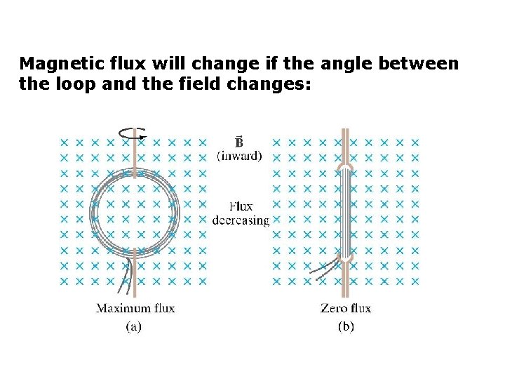
This gives us an important idea:
magnetic flux is about the field passing through a surface, not merely the magnetic field existing around it.
Magnetic Field Lines and Flux
Magnetic fields are often represented using magnetic field lines.
The arrows show the direction of the magnetic field.
The density of the lines helps us visualize field strength:
closer field lines → stronger magnetic field
more widely spaced field lines → weaker magnetic field


Field lines are a visual model; they are not physical strings in space. Their spacing is used to represent the strength of the magnetic field.
The Magnetic Flux Equation
For a uniform magnetic field:
Φ = BA cos θ
where:
Φ = magnetic flux, measured in webers (Wb)
B = magnetic flux density, measured in teslas (T)
A = area, measured in square metres (m²)
θ = angle between the magnetic field and the normal to the surface
This equation tells us exactly how field strength, area and orientation combine to determine magnetic flux.
The Unit of Magnetic Flux
The SI unit of magnetic flux is the:
weber (Wb)
Since:
Φ = BA
we can also write:
1 Wb = 1 T·m²
So if a magnetic field of 1 T passes perpendicularly through an area of 1 m²:
Φ = 1 Wb
What Is the Normal?
The angle in the flux equation is one of the most common sources of mistakes.
The angle θ is normally measured between:
the magnetic field B
and:
an imaginary line perpendicular to the surface
This perpendicular line is called the:
normal
Notice that θ is not normally measured between the magnetic field and the surface itself.
This distinction matters because the equation uses:
cos θ
Maximum Magnetic Flux
Magnetic flux is maximum when the magnetic field passes straight through the surface.
In this orientation:
θ = 0°
Therefore:
cos 0° = 1
So:
Φ = BA
The surface itself is perpendicular to the magnetic field.
Its normal is parallel to the field.
Zero Magnetic Flux
Now rotate the loop until its surface is parallel to the magnetic field.
The field lines travel along the plane of the loop rather than through it.
In this orientation:
θ = 90°
Since:
cos 90° = 0
then:
Φ = 0
The magnetic field can still be present and strong.
But none of it passes through the surface in the flux sense.
Orientation and Flux
As the loop rotates between these two positions, the magnetic flux changes continuously.
| Angle between B and normal | cos θ | Magnetic Flux |
|---|---|---|
| 0° | 1.00 | Maximum |
| 30° | 0.866 | Large |
| 45° | 0.707 | Moderate-large |
| 60° | 0.500 | Half maximum |
| 90° | 0 | Zero |
This relationship is extremely important in electrical generators.
As a generator coil rotates:
θ changes
therefore:
Φ changes
and that changing flux produces an induced EMF.
Effect of Magnetic Field Strength
Suppose area and orientation remain constant.
From:
Φ = BA cos θ
we can see that:
Φ ∝ B
Therefore:
stronger magnetic field → greater magnetic flux
If B doubles while everything else remains unchanged:
Φ doubles
If B triples:
Φ triples
This is a direct proportional relationship.
Example: Increasing Field Strength
A loop has:
A = 0.20 m²
and is perpendicular to the magnetic field.
Initially:
B = 0.40 T
Since θ = 0°:
Φ = BA
Φ = (0.40)(0.20)
Φ = 0.080 Wb
Now increase the field to:
B = 0.80 T
Then:
Φ = (0.80)(0.20)
Φ = 0.160 Wb
Doubling B doubled the magnetic flux.
Effect of Area
Magnetic flux also depends on the area exposed to the magnetic field.
From:
Φ = BA cos θ
if B and θ remain constant:
Φ ∝ A
Therefore:
larger area → greater magnetic flux
Imagine placing a small hoop and a large hoop in the same uniform magnetic field.


The larger loop encloses a larger surface, so more of the magnetic field passes through it.
Example: Increasing Area
A loop is perpendicular to a:
0.50 T
magnetic field.
Loop A has:
A = 0.10 m²
Therefore:
Φ = (0.50)(0.10)
Φ = 0.050 Wb
Loop B has:
A = 0.30 m²
Therefore:
Φ = (0.50)(0.30)
Φ = 0.150 Wb
Tripling the area tripled the magnetic flux.
Effect of Orientation
Orientation is slightly more complicated because it involves:
cos θ
Suppose B and A remain constant.
When:
θ = 0°
flux is maximum.
When:
θ = 60°
cos 60° = 0.5
so:
Φ = 0.5BA
The flux is half its maximum value.
When:
θ = 90°
flux becomes zero.
This changing orientation is one of the easiest ways to produce continuously changing magnetic flux.
The Three Ways to Change Magnetic Flux
From:
Φ = BA cos θ
we can immediately identify three ways to change magnetic flux.
Change B
Change the magnetic-field strength.
Change A
Change the area through which the field passes.
Change θ
Change the orientation of the surface relative to the field.
These are the three fundamental ways of changing flux.
Worked Example 1: Perpendicular Field
A loop has an area of:
0.040 m²
It is placed perpendicular to a uniform magnetic field of:
0.60 T
Calculate the magnetic flux.
Because the surface is perpendicular to the field:
θ = 0°
Use:
Φ = BA cos θ
Φ = (0.60)(0.040)(cos 0°)
Φ = 0.024 Wb
Answer:
Φ = 0.024 Wb
Worked Example 2: Field at an Angle
A loop has:
A = 0.20 m²
and is in a magnetic field:
B = 0.50 T
The magnetic field makes an angle of:
60°
with the normal.
Calculate the magnetic flux.
Use:
Φ = BA cos θ
Φ = (0.50)(0.20)(cos 60°)
Since:
cos 60° = 0.5
then:
Φ = (0.50)(0.20)(0.5)
Φ = 0.050 Wb
Worked Example 3: Zero Flux
A loop with area:
0.40 m²
is positioned so its surface is parallel to a:
2.0 T
magnetic field.
The normal is therefore at:
90°
to the field.
Use:
Φ = BA cos θ
Φ = (2.0)(0.40)(cos 90°)
Φ = 0 Wb
Notice:
B is not zero.
The magnetic field is actually quite strong.
The flux is zero because of the loop's orientation.
Worked Example 4: Finding Magnetic Field Strength
A loop has:
Φ = 0.060 Wb
and:
A = 0.20 m²
The field passes perpendicularly through the loop.
Since θ = 0°:
Φ = BA
Rearrange:
B = Φ/A
Substitute:
B = 0.060/0.20
B = 0.30 T
Worked Example 5: Finding Area
A magnetic flux of:
0.12 Wb
passes perpendicularly through a surface in a:
0.80 T
field.
Find the area.
Use:
Φ = BA
Rearrange:
A = Φ/B
Substitute:
A = 0.12/0.80
A = 0.15 m²
Be Careful with Area Units
Area must be measured in:
m²
Suppose a coil has area:
50 cm²
You cannot substitute 50 directly into the flux equation.
Because:
1 cm = 0.01 m
then:
1 cm² = 0.0001 m²
Therefore:
50 cm² = 50 × 10⁻⁴ m²
= 0.0050 m²
This conversion is a frequent source of mistakes.
Worked Example 6: Area Conversion
A loop has an area of:
200 cm²
and sits perpendicular to a:
0.30 T
field.
Convert:
200 cm² = 200 × 10⁻⁴ m²
= 0.020 m²
Now:
Φ = BA
Φ = (0.30)(0.020)
Φ = 0.0060 Wb
Interpreting Magnetic Flux Using Field Diagrams
Field diagrams provide a visual way to estimate magnetic flux.
Imagine three identical loops.
Loop A
Many field lines pass directly through it.
Large flux
Loop B
The loop is tilted.
Fewer lines effectively pass through its surface.
Smaller flux
Loop C
The loop is edge-on to the field.
No lines pass through its surface.
Zero flux
This visual interpretation matches:
Φ = BA cos θ
Field Lines Are a Model
It is tempting to think magnetic flux literally counts individual magnetic field lines.
It does not.
Magnetic field lines are a drawing convention used to represent the field.
Magnetic flux is a measurable physical quantity.
However, the field-line picture is extremely useful:
more field lines drawn through an area → larger represented flux
provided the diagrams use the same field-line scale.
Stronger Field in a Diagram
Compare two equal loops.
If one region has field lines that are more closely packed, it represents a stronger magnetic field.
Because:
Φ = BA cos θ
a stronger B gives a larger flux when A and θ are unchanged.


This allows us to compare flux qualitatively even without numerical values.
Magnetic Flux and Electromagnetic Induction
Magnetic flux becomes especially important because of Faraday's law of electromagnetic induction.
A changing magnetic flux through a conducting loop can produce an:
induced EMF
The key relationship is:
change in magnetic flux → induced EMF
A constant flux does not produce a continuous induced EMF.
A changing flux does.
Faraday's Law
For a single loop, the magnitude of the average induced EMF can be related to:
EMF = |ΔΦ/Δt|
For a coil containing N turns:
EMF = N|ΔΦ/Δt|
A more complete form is:
ε = −N ΔΦ/Δt
The negative sign represents Lenz's law and tells us about the direction of the induced EMF.
For now, the important magnitude relationship is:
larger rate of change of flux → larger induced EMF
Flux Linkage
If a coil contains many turns, the same magnetic flux may pass through each turn.
We therefore define:
magnetic flux linkage = NΦ
where:
N = number of turns
Φ = magnetic flux through one turn
A coil with more turns can therefore produce a larger induced EMF for the same rate of flux change.
How Moving a Magnet Changes Flux
Imagine a magnet approaching a coil.


As the magnet approaches:
magnetic field through coil increases
therefore:
magnetic flux increases
therefore:
an EMF is induced
When the magnet stops:
flux stops changing
therefore:
induced EMF falls to zero
When the magnet moves away:
flux decreases
therefore:
an EMF is induced in the opposite sense.
Static Flux vs Changing Flux
This distinction is essential.
Suppose a loop sits in a constant magnetic field.
It may have:
Φ = 0.50 Wb
That is a substantial magnetic flux.
But if it remains:
0.50 Wb
then:
ΔΦ = 0
Therefore:
no continuous induced EMF
Induction depends on:
change in flux
not simply:
having flux
Example: Changing Field Strength
A stationary coil is placed around an electromagnet.
Initially:
B = 0.20 T
Later:
B = 0.80 T
Even though neither the coil nor electromagnet moves, the magnetic flux changes because:
B changes
Therefore an EMF can be induced.
This is one reason alternating currents are so useful in electromagnetic devices.
Example: Changing Area
Suppose a conducting loop sits in a constant magnetic field.
If the loop is stretched so that its area increases:
A increases
therefore:
Φ increases
An EMF can therefore be induced even though:
- B stays constant
- orientation stays constant
Changing area alone can change flux.
Example: Changing Orientation
Suppose:
B = constant
and:
A = constant
but the loop rotates.
Then:
θ changes
so:
cos θ changes
therefore:
Φ changes
This produces an induced EMF.
This is the central principle behind an AC generator.
Flux in an Electrical Generator
In a simple generator, a coil rotates between magnetic poles.


As the coil rotates:
θ continuously changes
therefore:
Φ continuously changes
therefore:
an EMF is continuously induced
This is how mechanical rotation can be converted into electrical energy.
Flux During One Rotation
Imagine a coil rotating through 360°.
At:
0° → maximum positive flux
At:
90° → zero flux
At:
180° → maximum flux in the opposite direction
At:
270° → zero flux
At:
360° → back to maximum positive flux
So the magnetic flux varies continuously as the coil rotates.


This repeating change in flux is what allows a generator to produce alternating EMF.
Flux and EMF Are Not the Same Thing
This is an important distinction.
Magnetic flux tells us how much magnetic field passes through a surface.
Induced EMF depends on how quickly that flux changes.
So:
large flux does not automatically mean large EMF
For example, a stationary loop could have maximum flux but:
EMF = 0
because the flux is not changing.
Maximum Flux Can Mean Zero EMF at That Instant
This can initially seem surprising.
Suppose a rotating coil reaches an orientation where:
Φ is maximum
At that instant, the flux is momentarily changing at its slowest rate.
So the induced EMF can be:
zero at the instant of maximum flux
When the flux passes through zero, it can be changing most rapidly.
Then the induced EMF can be:
maximum
This becomes important when studying AC generators in more detail.
Worked Example 7: Change in Flux
A loop initially has:
Φ₁ = 0.080 Wb
Later:
Φ₂ = 0.020 Wb
Calculate the change in flux.
ΔΦ = Φ₂ − Φ₁
ΔΦ = 0.020 − 0.080
ΔΦ = −0.060 Wb
The negative sign indicates that the flux decreased.
The magnitude of the change is:
0.060 Wb
Worked Example 8: Induced EMF
The magnetic flux through a single loop changes from:
0.080 Wb
to:
0.020 Wb
in:
0.30 s
Magnitude of flux change:
|ΔΦ| = 0.060 Wb
Use:
|ε| = |ΔΦ|/Δt
|ε| = 0.060/0.30
|ε| = 0.20 V
The average induced EMF has magnitude:
0.20 V
Worked Example 9: Coil with Many Turns
A 200-turn coil experiences a flux change per turn of:
0.015 Wb
in:
0.50 s
Use:
|ε| = N|ΔΦ|/Δt
Substitute:
|ε| = 200(0.015)/0.50
|ε| = 6.0 V
This shows why practical generators and transformers often use coils containing many turns.
Comparing Two Flux Situations
Consider identical loops.
Loop A
B = 0.50 T
A = 0.20 m²
θ = 0°
Φ = 0.50 × 0.20 × 1
Φ = 0.10 Wb
Loop B
B = 0.50 T
A = 0.20 m²
θ = 60°
Φ = 0.50 × 0.20 × 0.5
Φ = 0.050 Wb
Loop B has half the magnetic flux because of its orientation.
Predicting Flux Without Calculating
Sometimes you only need to predict whether flux increases, decreases or stays the same.
Increase B
Flux increases.
Decrease B
Flux decreases.
Increase A
Flux increases.
Decrease A
Flux decreases.
Rotate from θ = 0° toward 90°
Flux decreases.
Rotate from θ = 90° toward 0°
Flux increases.
This follows directly from:
Φ = BA cos θ
What If Several Factors Change?
Suppose:
B doubles
but:
A halves
and θ stays the same.
Original:
Φ = BA cos θ
New:
Φ = (2B)(A/2)cos θ
The 2 and 1/2 cancel.
Therefore:
flux stays the same
Even though both B and A changed.
This is why it is important to consider all parts of the equation.
Challenge Example
A loop has:
A = 0.080 m²
and sits in a:
0.75 T
magnetic field.
The angle between B and the normal is:
40°
Calculate the magnetic flux.
Use:
Φ = BA cos θ
Φ = (0.75)(0.080)(cos 40°)
Φ ≈ (0.060)(0.766)
Φ ≈ 0.046 Wb
Challenge Example: Finding the Angle
A loop has:
B = 0.50 T
A = 0.20 m²
and magnetic flux:
Φ = 0.050 Wb
Use:
Φ = BA cos θ
Substitute:
0.050 = (0.50)(0.20)cos θ
0.050 = 0.10 cos θ
Therefore:
cos θ = 0.50
So:
θ = 60°
Remember:
This is the angle between the magnetic field and the normal to the surface.
Interpreting Field Diagrams
When looking at a field diagram, ask three questions.
1. How strong is the field?
Look at field-line density.
2. How large is the area?
A larger enclosed area can produce greater flux.
3. How is the surface oriented?
Look at how directly the field passes through the surface.


These correspond directly to:
B, A and θ
in:
Φ = BA cos θ
A Useful Visual Analogy: Rain Through a Window
Imagine rain falling straight downward.
A horizontal opening catches a large amount of rain.
Tilt the opening and less rain passes through it.
Turn it vertically and almost no rain passes through the opening.
Magnetic flux behaves similarly.
The "rain" represents:
magnetic field
The opening represents:
area
The tilt represents:
orientation
The amount passing through represents:
flux
The analogy is not perfect, but it helps visualize why the cosine term appears.
Magnetic Flux Is Not Magnetic Field Strength
Another important distinction:
B = magnetic field strength / magnetic flux density
Φ = magnetic flux
They are related but not the same.
B describes the magnetic field at a region.
Φ describes how that field passes through a particular surface.
A small area in a strong field may have the same flux as a larger area in a weaker field.
Example
Situation A:
B = 2 T
A = 0.10 m²
Flux:
Φ = 0.20 Wb
Situation B:
B = 0.5 T
A = 0.40 m²
Flux:
Φ = 0.20 Wb
The magnetic fields are different, but the magnetic fluxes are equal.
Common Misconception: Flux Is the Number of Field Lines
Field lines are only a visual representation.
Magnetic flux is not literally obtained by counting drawn lines.
The actual quantity is determined from:
Φ = BA cos θ
for a uniform field and flat surface.
Common Misconception: Maximum Flux Occurs at 90°
This depends on which angle you are measuring.
In:
Φ = BA cos θ
θ is measured between:
B and the normal
Therefore:
θ = 0° → maximum flux
θ = 90° → zero flux
Always identify the normal before using the equation.
Common Misconception: Strong Magnetic Field Means Large EMF
Not necessarily.
A strong but constant magnetic field can produce:
zero induced EMF
if the flux is not changing.
EMF depends on:
rate of change of magnetic flux
not simply magnetic-field strength.
Common Misconception: Moving a Magnet Always Produces an EMF
Motion matters only if it changes the magnetic flux through the circuit.
The deeper principle is not simply:
movement → EMF
It is:
movement → changing flux → EMF
This distinction becomes important in more complicated induction situations.
Common Misconception: Flux Must Change Because the Coil Moves
Not necessarily.
Imagine moving a coil sideways through a perfectly uniform magnetic field while:
- B stays constant
- A stays constant
- θ stays constant
- the entire loop remains inside the same uniform field
Then:
Φ = BA cos θ
remains unchanged.
Therefore that motion alone does not necessarily produce an induced EMF around the loop.
It is changing flux, rather than motion by itself, that matters.
Real-World Connection: Electrical Generators
Generators deliberately change magnetic flux.
Mechanical energy rotates coils or magnets.
This changes:
θ
and therefore:
Φ
The changing flux produces an induced EMF.
This principle is used in generators driven by:
- wind turbines
- hydroelectric turbines
- steam turbines
- gas turbines
- hand cranks
Real-World Connection: Transformers
Transformers change magnetic flux in a different way.
The coils do not need to rotate.
Instead, alternating current in the primary coil creates a:
changing magnetic field
This changes B.
Therefore the magnetic flux through the secondary coil changes.
The changing flux induces an EMF in the secondary coil.
So generators and transformers use the same fundamental principle but change flux in different ways.
Real-World Connection: Wireless Charging
Wireless charging also depends on changing magnetic flux.
Alternating current in the charging pad creates a changing magnetic field.
That changing field passes through a receiving coil inside the device.
Therefore:
Φ changes
which produces:
induced EMF
which allows electrical energy to be transferred to the device.
Did You Know?
The weber is named after German physicist Wilhelm Eduard Weber.
One weber is equivalent to:
1 T·m²
and also:
1 V·s
The second relationship connects magnetic flux directly to electromagnetic induction.
A change of magnetic flux of 1 Wb occurring uniformly in 1 second through a single loop corresponds to an average induced EMF magnitude of:
1 V
A Strong Magnetic Flux Explanation
Suppose the question asks:
Explain why rotating a coil in a magnetic field can produce an induced EMF.
A weak answer:
"The coil moves through the magnetic field."
A stronger answer:
"Rotating the coil changes the angle between the magnetic field and the normal to the coil. Since Φ = BA cos θ, the magnetic flux through the coil changes. According to Faraday's law, a changing magnetic flux produces an induced EMF."
This gives the complete chain:
rotation
→ θ changes
→ magnetic flux changes
→ EMF induced
A Strong Field-Diagram Explanation
Suppose two identical loops are shown in the same field.
Loop A is face-on to the field.
Loop B is edge-on.
A strong explanation is:
"Loop A has greater magnetic flux because the magnetic field passes perpendicularly through its surface. Its normal is parallel to the field, so θ = 0° and Φ = BA. Loop B has zero flux because its surface is parallel to the field, making θ = 90° and Φ = 0."
This combines:
diagram interpretation + geometry + equation
Key Terms
Magnetic flux (Φ) – Measure of magnetic field passing through a surface.
Magnetic flux density (B) – Measure of magnetic-field strength, measured in teslas.
Weber (Wb) – SI unit of magnetic flux.
Tesla (T) – SI unit of magnetic flux density.
Area (A) – Surface area through which magnetic flux is measured.
Normal – Imaginary line perpendicular to a surface.
Orientation – Direction of a surface relative to the magnetic field.
Magnetic field line – Visual representation of magnetic-field direction and relative strength.
Flux linkage – Product of magnetic flux and number of turns: NΦ.
Induced EMF – Voltage produced by changing magnetic flux.
Faraday's law – Relationship between induced EMF and the rate of change of magnetic flux linkage.
Key Takeaways
- Magnetic flux describes how much magnetic field passes through a surface.
- Magnetic flux is represented by Φ.
- The SI unit of magnetic flux is the weber (Wb).
- For a uniform field and flat surface:
Φ = BA cos θ
- B is magnetic flux density in teslas.
- A must be measured in square metres.
- θ is the angle between the magnetic field and the normal to the surface.
- Stronger magnetic fields produce greater flux when other factors remain constant.
- Larger areas produce greater flux when other factors remain constant.
- Orientation affects flux through the cosine relationship.
- Flux is maximum when θ = 0°.
- Flux is zero when θ = 90°.
- Magnetic field lines help us visualize magnetic flux but are not physical objects.
- A strong magnetic field does not automatically mean a large induced EMF.
- A constant magnetic flux produces no continuous induced EMF.
- Changing B, A or θ can change magnetic flux.
- Changing magnetic flux can produce an induced EMF.
- Faster flux change produces a larger induced EMF.
- Multiple turns increase flux linkage and can increase induced EMF.
- Generators change flux by rotating coils or magnets.
- Transformers change flux using changing magnetic fields.
- The central relationship is:
B, A or θ changes → magnetic flux changes → EMF is induced.