Fundamentals of Electromagnetic Induction
| Website: | Young Education |
| Kurs: | Induction |
| Buch: | Fundamentals of Electromagnetic Induction |
| Gedruckt von: | Guest user |
| Datum: | Freitag, 25. September 2026, 01:05 |
1. Introduction to Electromagnetic Induction
Learning outcomes
- I can describe electromagnetic induction as the production of an EMF by a changing magnetic field.
- I can explain how moving magnets or conductors produce induced voltage.
- I can identify situations where electromagnetic induction occurs.
- I can distinguish between static magnetic fields and changing magnetic fields.
- I can explain why electromagnetic induction is important in modern technology.
What Is Electromagnetic Induction?
Electromagnetic induction is the production of an electromotive force (EMF), or induced voltage, when the magnetic environment of a conductor changes.
A simple example is a bar magnet moving toward or away from a coil of wire.

When the magnet is moving relative to the coil, the magnetic field passing through the coil changes.
This changing magnetic field produces an induced EMF.
If the coil forms part of a complete electrical circuit, the induced EMF can drive an induced current through the circuit.
The central idea is:
changing magnetic field through a conductor → induced EMF
EMF Does Not Mean a Mechanical Force
The term electromotive force, usually written as EMF, can be misleading.
An EMF is not a pushing force measured in newtons.
It is a voltage-like quantity measured in:
volts (V)
An induced EMF provides energy per unit charge that can cause charges to move through a circuit.
So in introductory work, it is often helpful to think of:
induced EMF ≈ induced voltage
A Classic Induction Experiment
Imagine a coil of wire connected to a sensitive voltmeter or galvanometer.
A bar magnet is moved toward the coil.

As the magnet approaches:
- the magnetic field through the coil changes
- an EMF is induced
- the meter shows a deflection
If the circuit is closed, a current flows.
If the magnet is pulled away:
- the magnetic field changes in the opposite way
- an EMF is again induced
- the induced current reverses direction
If the magnet is held still relative to the coil:
no changing magnetic field
so:
no induced EMF.
Relative Motion Is What Matters
It is not necessary for the magnet itself to move.
You could keep the magnet stationary and move the coil instead.
What matters is:
relative motion between the conductor and the magnetic field
For example:
Magnet moves, coil stationary
Induction occurs.
Coil moves, magnet stationary
Induction occurs.
Both remain stationary relative to one another
No induction occurs from that static arrangement.
OpenStax notes that the same induction effect occurs whether the magnet moves or the coil moves; it is the relative motion that matters.
Static Magnetic Field vs Changing Magnetic Field
A magnetic field can exist without producing electromagnetic induction.
This is one of the most important distinctions in this topic.
Static magnetic field
A magnetic field that remains constant through the conductor.
Example:
A magnet is placed beside a stationary coil and neither moves.
The coil may be inside a magnetic field, but if the field through the coil is not changing:
no induced EMF is produced.
Changing magnetic field
If the amount or direction of magnetic field passing through the conductor changes:
an EMF can be induced.
This can happen because:
- a magnet moves
- a conductor moves
- the magnetic-field strength changes
- the conductor rotates
- the conductor's orientation changes
- an alternating current produces a changing magnetic field
The Key Rule
A useful rule is:
A magnetic field alone is not enough.
There must be a:
change in magnetic flux through the conductor
for electromagnetic induction to occur.
At an introductory level, we can think of magnetic flux as:
how much magnetic field passes through a loop or coil.
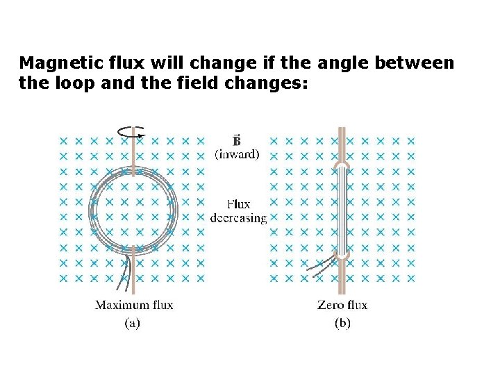
Magnetic Flux
Magnetic flux is related to:
- magnetic-field strength
- area of the coil
- angle of the coil relative to the magnetic field
The symbol for magnetic flux is:
Φ
For a uniform magnetic field:
Φ = BA cos θ
where:
- Φ = magnetic flux
- B = magnetic-field strength
- A = area
- θ = angle between the magnetic field and the perpendicular to the surface
You do not need this equation to understand the basic concept, but it explains why induction can occur even if neither the magnet nor coil moves closer or farther apart.
For example, simply rotating a coil in a magnetic field changes the angle and therefore changes the magnetic flux.
Faraday's Law
Michael Faraday discovered that induced EMF depends on how quickly magnetic flux changes.
In simplified form:
induced EMF ∝ rate of change of magnetic flux
For a coil of N turns:
ε = −N ΔΦ/Δt
where:
- ε = induced EMF
- N = number of turns
- ΔΦ = change in magnetic flux
- Δt = time taken for the change
The negative sign is associated with Lenz's law, which describes the direction of the induced EMF.
For this introductory topic, the main idea is:
faster change in magnetic flux → larger induced EMF.
Moving a Magnet Faster
Suppose you push a magnet slowly into a coil.
The magnetic field through the coil changes slowly.
The induced EMF is relatively small.
Now push the same magnet quickly into the same coil.
The magnetic field changes more rapidly.
Therefore:
larger induced EMF
The same principle applies when pulling the magnet out.
OpenStax describes that faster relative motion produces a greater induced EMF.
Moving Magnet: Three Situations
Consider these three cases.
Magnet moving into coil
Magnetic flux changes.
EMF induced
Magnet held still inside coil
Magnetic flux remains constant.
No EMF induced
Magnet moving out of coil
Magnetic flux changes again.
EMF induced in the opposite direction
The direction of the induced current changes when the direction of motion changes.
Changing the Magnet's Pole
Suppose the north pole of a magnet is pushed toward a coil.
The induced current flows in one direction.
Now repeat the experiment using the south pole.
The induced current reverses direction.
Why?
Because the direction of the magnetic-field change through the coil has reversed.
This observation helped scientists establish that both the size and direction of the magnetic-field change matter.
How Can a Conductor Moving Through a Magnetic Field Produce Voltage?
Electromagnetic induction can also occur when a straight conductor moves through a magnetic field.
Imagine a metal rod moving across magnetic field lines.
Charges inside the conductor experience magnetic effects.
Positive and negative charges become separated.
This produces a potential difference across the ends of the conductor.
That potential difference is an:
induced EMF
So another useful description is:
when a conductor cuts across magnetic field lines, an EMF can be induced.
Moving Conductor Example
Suppose a straight wire moves through a uniform magnetic field.
If the wire cuts across the magnetic field:
charges in the wire experience magnetic forces
which can lead to:
charge separation
and therefore:
induced voltage
If the conductor is connected into a complete circuit, that voltage can drive a current.
This idea forms the basis of an electrical generator.
Factors That Affect the Induced EMF
The induced EMF can generally be increased by:
- moving the magnet faster
- moving the conductor faster
- using a stronger magnetic field
- increasing the number of turns in the coil
- increasing the area through which the magnetic field changes
- changing the magnetic flux more rapidly
The unifying idea is:
increase the rate of change of magnetic flux
Example: Slow vs Fast Magnet Motion
Experiment A:
A magnet moves into a coil in:
2.0 s
Experiment B:
The same magnet moves through the same distance in:
0.5 s
The change in magnetic flux is similar, but Experiment B produces the change in a shorter time.
Therefore:
Experiment B produces a larger induced EMF.
More Coil Turns
Imagine two coils.
Coil A:
50 turns
Coil B:
500 turns
The same changing magnetic flux passes through each turn.
Because the effects from all the turns add together, Coil B can produce a larger induced EMF.
This is reflected in Faraday's law:
ε = −N ΔΦ/Δt
A larger N can produce a larger EMF.
Stronger Magnetic Field
Suppose the same coil is used with two magnets.
Magnet A produces a relatively weak field.
Magnet B produces a much stronger field.
If both magnets move through the coil at the same speed, the stronger magnet generally creates a larger change in magnetic flux.
Therefore:
larger induced EMF
Static Does Not Mean "No Magnetism"
A common misconception is:
"If no EMF is induced, there must be no magnetic field."
Incorrect.
A coil can sit inside a strong magnetic field and still have:
zero induced EMF
if the magnetic flux through it remains constant.
Electromagnetic induction depends on:
change
not merely the existence of a magnetic field.
Example: Magnet Sitting Inside a Coil
Imagine a bar magnet placed halfway inside a coil.
The magnetic field through the coil may be strong.
But if the magnet stays completely still:
magnetic flux is constant
Therefore:
no induced EMF
Now pull the magnet out.
The flux changes.
Therefore:
an EMF is induced.
This difference between field strength and change in field is fundamental.
How Can the Magnetic Field Change Without Moving a Magnet?
A magnet does not always have to physically move.
A changing current can produce a changing magnetic field.
For example, an alternating current in one coil creates a continuously changing magnetic field around that coil.
If another coil is nearby, that changing field can induce an EMF in the second coil.
This is the operating principle of a:
transformer
Transformers
A transformer contains two coils:
- primary coil
- secondary coil
usually wound around a magnetic core.
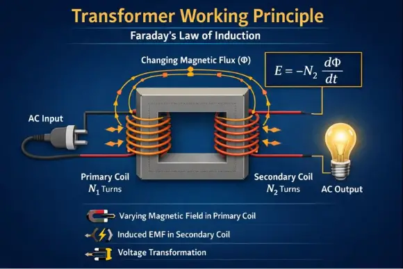
Alternating current in the primary coil produces a changing magnetic field in the core.
That changing magnetic flux passes through the secondary coil.
An EMF is therefore induced in the secondary coil.
Transformers can increase or decrease AC voltage depending on the number of turns in the two coils.
Why Direct Current Does Not Continuously Work in a Transformer
If a steady direct current flows through the primary coil:
the magnetic field becomes steady after switching.
A steady field means:
no continuous change in magnetic flux
Therefore:
no continuous induced EMF in the secondary coil
There may be a brief induced effect when the current is switched on or off because the magnetic field is changing during those moments.
This is why ordinary transformers depend on:
alternating current
rather than steady DC.
Electromagnetic Induction in Generators
One of the most important applications of electromagnetic induction is the:
electrical generator
A generator converts:
mechanical energy → electrical energy
It usually does this by creating relative motion between:
- a conductor or coil
- a magnetic field
When a coil rotates in a magnetic field, the magnetic flux through the coil changes continuously.
This induces an EMF.
That is how mechanical motion can be converted into electrical output.
Electromagnetic induction is the basic principle behind electric generators.
How a Generator Works
A simple generator can contain:
- a rotating coil
- magnetic poles
- an axle
- electrical contacts
As the coil rotates:
the angle between the coil and magnetic field changes.
Therefore:
magnetic flux changes
so:
an EMF is induced
Continued rotation produces a continuously changing induced voltage.
Where Does the Energy Come From?
Induction does not create electrical energy from nothing.
In a generator, someone or something must provide mechanical energy.
Examples include:
- falling water
- steam turbines
- wind
- a hand crank
- an engine
The generator converts this mechanical energy into electrical energy.
This is an important conservation-of-energy idea.
Power Stations
Most large-scale electrical generation ultimately relies on electromagnetic induction.
A power station may use:
- steam
- water
- wind
- gas turbines
- nuclear-generated steam
to rotate a turbine.
The turbine turns a generator.
The generator uses electromagnetic induction to produce electrical energy.
So despite having very different energy sources, many power stations share the same final step:
rotate generator → change magnetic flux → induce EMF
Hydroelectric Power
In a hydroelectric station:
- water falls or flows
- the water turns a turbine
- the turbine rotates a generator
- magnetic flux through coils changes
- an EMF is induced
- electrical energy is produced
Electromagnetic induction provides the connection between:
mechanical rotation
and:
electricity generation
Wind Turbines
Wind turbines use the same fundamental principle.
Wind provides kinetic energy.
The blades rotate.
That rotation drives a generator.
Inside the generator:
relative motion between magnets and conductors produces changing magnetic flux
which induces an EMF.
So a wind turbine is not "making electricity directly from wind."
Instead:
wind → mechanical rotation → electromagnetic induction → electrical energy
Bicycle Dynamo
A bicycle dynamo is a small generator.
As the bicycle wheel turns, the dynamo rotates a magnet or coil.
The resulting change in magnetic flux induces an EMF.
This can power:
bicycle lights
It is a simple everyday example of electromagnetic induction.
Induction Cooktops
Electromagnetic induction is also used for heating.
An induction cooktop contains a coil carrying alternating current.
This creates a rapidly changing magnetic field.
The changing magnetic field induces electrical currents in suitable metal cookware.
These currents produce heating because of the electrical resistance of the cookware.
So:
changing current
→ changing magnetic field
→ induced currents
→ heating
Wireless Charging
Many wireless chargers also use electromagnetic induction.
A coil in the charging pad carries alternating current.
This creates a changing magnetic field.
A second coil inside the device experiences the changing magnetic flux.
An EMF is induced in the device's coil.
That electrical energy can then be used to charge the battery.
The device does not need direct metal-to-metal electrical contact between charger and phone.
Electric Guitar Pickups
Electromagnetic induction is also used in many electric guitars.
The guitar strings affect the magnetic field near a pickup coil.
When a magnetized string vibrates, the magnetic flux through the pickup coil changes.
This induces a small voltage.
The changing electrical signal corresponds to the vibration of the string and can be amplified into sound.
OpenStax includes guitar pickup coils among devices using electromagnetic induction.
Dynamic Microphones
Some microphones use electromagnetic induction.
A sound wave vibrates a diaphragm.
The diaphragm moves a coil relative to a magnetic field.
This motion changes magnetic flux through the coil.
A small EMF is induced.
The changing voltage becomes an electrical representation of the sound wave.
Why Electromagnetic Induction Is So Important
Modern electrical technology depends heavily on induction.
It allows us to:
- generate electricity
- change AC voltage
- transfer electrical energy without direct contact
- convert sound into electrical signals
- detect metal
- produce heating
- operate sensors
- convert mechanical motion into electrical signals
Without electromagnetic induction, modern power distribution would look completely different.
Induction and the Electrical Grid
Generators at power stations produce electrical energy.
Transformers then change voltage levels.
High voltages are useful for long-distance transmission because they help reduce energy losses in power lines.
Other transformers later reduce the voltage for homes, businesses, and electronic devices.
Both generators and transformers depend fundamentally on:
changing magnetic flux
This makes electromagnetic induction one of the central ideas behind the modern electrical grid.
Static vs Changing Field: Comparison
| Situation | Magnetic Field Present? | Magnetic Flux Changing? | Induced EMF? |
|---|---|---|---|
| Magnet beside stationary coil | Yes | No | No |
| Magnet moving toward coil | Yes | Yes | Yes |
| Magnet moving away from coil | Yes | Yes | Yes |
| Coil moving past magnet | Yes | Yes | Yes |
| Coil rotating in magnetic field | Yes | Yes | Yes |
| Steady DC producing steady field | Yes | No after settling | No continuous EMF |
| Alternating current producing field | Yes | Yes | Yes in nearby coil |
The crucial column is:
Magnetic flux changing?
Predicting Whether Induction Occurs
Consider each situation.
Situation 1
A magnet rests motionless next to a coil.
Prediction:
No induced EMF
Reason:
The magnetic field through the coil is not changing.
Situation 2
The magnet is pushed into the coil.
Prediction:
EMF induced
Reason:
The magnetic flux through the coil changes.
Situation 3
The coil is pulled away from a stationary magnet.
Prediction:
EMF induced
Reason:
Relative motion changes the magnetic flux.
Situation 4
A coil rotates continuously between magnetic poles.
Prediction:
Continuously changing induced EMF
Reason:
The angle between the coil and field changes continuously.
Situation 5
A nearby electromagnet is supplied with alternating current.
Prediction:
EMF can be induced in the coil
Reason:
The electromagnet produces a changing magnetic field.
Predicting the Size of the Induced EMF
Suppose the same magnet and coil are used.
Slow movement
Small rate of change of magnetic flux.
Smaller EMF
Fast movement
Large rate of change of magnetic flux.
Larger EMF
This gives another useful relationship:
faster flux change → larger induced EMF
Example Calculation Idea
Suppose the magnetic flux through a single loop changes from:
0.020 Wb
to:
0.005 Wb
in:
0.50 s
Change in flux magnitude:
ΔΦ = 0.015 Wb
Approximate induced EMF magnitude:
ε = ΔΦ/Δt
ε = 0.015 / 0.50
ε = 0.030 V
For a coil of 100 identical turns:
ε = NΔΦ/Δt
ε = 100(0.015/0.50)
ε = 3.0 V
This demonstrates why coils with many turns can generate larger voltages.
What Is an Induced Current?
An induced EMF can exist even if the circuit is open.
If the circuit is closed:
the induced EMF can cause charges to flow.
This flow of charge is called:
induced current
So it is useful to distinguish:
EMF = induced voltage
from:
current = movement of charge caused when a complete conducting path exists
Example: Open vs Closed Circuit
Suppose a magnet moves through a coil.
Coil connected to voltmeter only
An induced voltage can be detected.
Coil connected as part of a closed circuit
The induced EMF can drive a current.
Therefore, induction first describes the creation of:
EMF
A current requires:
a complete circuit
Direction of Induced Current
The direction of the induced current depends on how the magnetic flux is changing.
For example:
magnet moving into coil → current in one direction
magnet moving out → current in opposite direction
This is explained in more detail by:
Lenz's law
which states that the induced effect acts in a direction that opposes the change that produced it.
A Preview of Lenz's Law
Suppose a north pole approaches a coil.
The increasing magnetic flux induces a current.
The magnetic field created by that current acts to oppose the increase in flux.
If the magnet is pulled away:
the induced current reverses so that its magnetic effect opposes the decrease in flux.
This does not mean the system somehow "knows" what is happening.
It follows from electromagnetic laws and conservation of energy.
Why Must the Induced Effect Oppose the Change?
Imagine instead that the induced current strengthened the original change.
A magnet moving toward a coil would cause a current that pulled it in even faster.
The increasing motion would create more current, causing even more motion.
Energy could appear without an external energy source.
That would violate conservation of energy.
Lenz's law prevents this.
Common Misconception: A Magnet Automatically Produces Electricity
Incorrect.
A stationary magnet beside a stationary wire does not automatically create a continuous induced voltage.
What is required is:
changing magnetic flux
A magnet is useful because moving it can create that change.
Common Misconception: The Magnet Must Move
Incorrect.
The conductor can move instead.
Or neither has to translate through space if the magnetic field itself changes.
For example:
- rotating coil
- alternating electromagnet
- changing current in a nearby coil
can all produce induction.
Common Misconception: A Stronger Field Always Means Induction
A strong but perfectly constant magnetic field may produce:
no induced EMF
A weaker magnetic field that changes rapidly can produce an induced EMF.
Therefore, the key idea is not simply:
how strong is the field?
but:
how quickly is the magnetic flux changing?
Common Misconception: EMF and Current Are the Same
They are related but different.
EMF is measured in volts.
Current is measured in amperes.
An induced EMF can exist without a current if the circuit is incomplete.
Common Misconception: Generators Create Energy
Generators do not create energy.
They convert:
mechanical energy
into:
electrical energy
Energy must be supplied to turn the generator.
Common Misconception: A Transformer Creates Extra Energy
A transformer may increase voltage, but this does not mean it creates energy.
In an ideal transformer, increasing voltage is accompanied by a decrease in current.
Real transformers also lose some energy, usually as heat.
The role of a transformer is:
energy transfer and voltage transformation
through electromagnetic induction.
A Useful Cause-and-Effect Chain
For induction problems, use:
something changes the magnetic environment
↓
magnetic flux through conductor changes
↓
EMF is induced
↓
current flows if circuit is complete
This chain is extremely useful.
Technology Example Summary
| Technology | What Changes? | Result |
|---|---|---|
| Generator | Coil or magnet moves | EMF produced |
| Transformer | Current in primary changes | EMF in secondary |
| Wireless charger | Magnetic field alternates | EMF in receiving coil |
| Bicycle dynamo | Magnet/coil rotates | EMF powers light |
| Dynamic microphone | Coil moves with sound | Audio voltage produced |
| Guitar pickup | String changes magnetic flux | Signal voltage produced |
| Induction cooker | Magnetic field changes rapidly | Currents induced in pan |
Electromagnetic induction links magnetism and electricity in an extraordinarily useful way.
Real-World Connection: From Motion to Electricity
Consider a hand-cranked generator.
Your muscles provide chemical energy.
That becomes:
mechanical energy
as you turn the handle.
The spinning generator changes magnetic flux.
Electromagnetic induction produces an EMF.
Electrical energy can then power a lamp.
Energy pathway:
chemical → mechanical → electrical → light + thermal
Induction is the key step between mechanical and electrical energy.
Real-World Connection: Charging Without Wires
In inductive charging:
one coil creates a changing magnetic field.
A second coil experiences the changing field.
This induces a voltage.
Because the coils do not need direct conductive contact, energy can cross a small gap.
Applications include:
- phones
- electric toothbrushes
- some medical devices
- some electric vehicle charging systems
Did You Know?
Michael Faraday demonstrated electromagnetic induction in 1831.
His work established a direct connection between changing magnetic fields and electrical effects.
This discovery became one of the foundations of modern electrical technology.
Generators and transformers now allow electrical energy to be produced and distributed on enormous scales.
A Simple Classroom Demonstration
A basic induction demonstration requires:
- coil of insulated wire
- bar magnet
- sensitive galvanometer or voltmeter
Try:
- Hold the magnet still near the coil.
- Move the north pole rapidly into the coil.
- Hold it still.
- Pull it rapidly out.
- Repeat slowly.
- Reverse the magnet.
Expected observations:
- stationary magnet → no meter deflection
- moving magnet → meter deflection
- faster movement → larger deflection
- reversing movement → opposite deflection
- reversing pole → opposite deflection
These observations provide direct evidence for electromagnetic induction.
Interpreting Experimental Results
Suppose a student records:
| Magnet Motion | Meter Reading |
|---|---|
| Stationary | 0 V |
| Slowly toward coil | +0.2 V |
| Quickly toward coil | +0.7 V |
| Slowly away | −0.2 V |
| Quickly away | −0.7 V |
We can conclude:
- induction requires changing magnetic flux
- faster change produces larger EMF
- reversing the change reverses the EMF direction
This is a strong experimental summary of the topic.
Predicting Changes
Move magnet faster
Induced EMF increases
Use stronger magnet
Induced EMF usually increases
Add more turns to coil
Induced EMF increases
Stop the magnet
Induced EMF falls to zero
Reverse magnet direction
Induced EMF reverses direction
Rotate coil faster
Induced EMF generally increases
Static and Changing Fields: Final Comparison
A static magnetic field can exert magnetic forces.
However:
static magnetic field through a stationary coil → no continuous induced EMF
A changing magnetic field can produce:
induced EMF
This is the defining idea of electromagnetic induction.
Key Terms
Electromagnetic induction – Production of an EMF due to a changing magnetic flux through a conductor.
EMF – Electromotive force; a voltage associated with energy supplied per unit charge.
Induced EMF – Voltage produced by electromagnetic induction.
Induced current – Current caused by an induced EMF in a complete circuit.
Magnetic field – Region in which magnetic effects can act.
Static magnetic field – Magnetic field that remains constant with time in the relevant situation.
Changing magnetic field – Magnetic field whose magnitude or direction changes.
Magnetic flux – Measure of magnetic field passing through a surface.
Coil – Wire wound into loops, often used to increase induction effects.
Generator – Device that converts mechanical energy into electrical energy using electromagnetic induction.
Transformer – Device that transfers electrical energy between coils using changing magnetic flux.
Faraday's law – Relationship between induced EMF and the rate of change of magnetic flux.
Lenz's law – Rule stating that the induced effect opposes the change in magnetic flux that caused it.
Key Takeaways
- Electromagnetic induction is the production of an EMF by changing magnetic flux.
- A static magnetic field alone does not necessarily produce an induced EMF.
- Moving a magnet relative to a coil can produce an EMF.
- Moving the coil relative to the magnet produces the same basic effect.
- Relative motion is what matters.
- A conductor moving through a magnetic field can also develop an induced voltage.
- A changing current can produce a changing magnetic field and induce an EMF in another coil.
- Faster changes in magnetic flux generally produce larger induced EMFs.
- Stronger fields and more coil turns can increase induced EMF.
- Reversing the magnetic-field change reverses the induced EMF direction.
- An induced current flows only if there is a complete conducting circuit.
- Generators use electromagnetic induction to convert mechanical energy into electrical energy.
- Transformers use changing magnetic fields to transfer electrical energy between coils.
- Wireless chargers, microphones, guitar pickups, dynamos, and induction cookers also use electromagnetic induction.
- Modern electricity generation and distribution depend heavily on this principle.
- The essential relationship is:
changing magnetic flux → induced EMF → induced current if the circuit is complete.
2. Magnetic Flux
Learning outcomes
- I can define magnetic flux and describe what it represents.
- I can explain how magnetic field strength, area, and orientation affect magnetic flux.
- I can calculate magnetic flux for simple situations.
- I can determine how changing magnetic flux produces induced EMF.
- I can interpret magnetic flux using field diagrams.



3. Faraday’s and Lenz’s Laws
Learning outcomes
- I can state Faraday's Law of electromagnetic induction.
- I can explain how the rate of change of magnetic flux affects induced EMF.
- I can describe Lenz's Law and explain why induced currents oppose changes in flux.
- I can determine the direction of induced current using Lenz's Law.
- I can solve simple induction problems using Faraday's Law.
From Magnetic Flux to Induced EMF
In the previous topic, we saw that magnetic flux describes how much magnetic field passes through a surface.
For a uniform magnetic field:
Φ = BA cos θ
Electromagnetic induction occurs when that magnetic flux changes.
Faraday’s Law tells us how the size of the induced EMF depends on the rate at which magnetic flux changes. Lenz’s Law tells us the direction of the induced EMF and current.
The basic chain is:
magnetic flux changes
→ EMF is induced
→ current flows if the circuit is complete
Faraday's Law
Faraday's Law states:
The induced EMF is proportional to the rate of change of magnetic flux linkage.
For a coil:
ε = −N(ΔΦ/Δt)
where:
- ε = induced EMF, measured in volts (V)
- N = number of turns in the coil
- ΔΦ = change in magnetic flux, measured in webers (Wb)
- Δt = time over which the change occurs, measured in seconds (s)
The negative sign is connected to Lenz's Law.

What Is Magnetic Flux Linkage?
For one loop:
magnetic flux = Φ
For a coil containing N turns:
magnetic flux linkage = NΦ
If the same flux passes through every turn, increasing the number of turns increases the total flux linkage.
Therefore:
more turns → larger induced EMF
for the same rate of flux change.
This is one reason practical generators and transformers use coils containing many turns.
The Meaning of Rate of Change
Faraday's Law does not simply depend on how much the magnetic flux changes.
It depends on:
how quickly the change occurs
Compare two situations.
Situation A
Flux changes by:
0.20 Wb
in:
4.0 s
Rate of change:
0.20 / 4.0 = 0.050 Wb/s
Situation B
The same flux change occurs in:
0.50 s
Rate of change:
0.20 / 0.50 = 0.40 Wb/s
Situation B produces the larger induced EMF because the change happens much more quickly.
Faster Flux Change Means Greater EMF
Faraday's Law can be written in terms of magnitude as:
|ε| = N|ΔΦ|/Δt
Therefore:
larger ΔΦ → larger EMF
and:
smaller Δt → larger EMF
provided the other quantities remain unchanged.
OpenStax describes induced EMF as directly proportional to the change in flux and inversely proportional to the time over which that change occurs.

Moving a Magnet Faster
Consider a bar magnet moving toward a coil.
Moving it slowly produces a gradual change in magnetic flux.
Moving it quickly produces a much faster change.
Therefore:
faster magnet → faster flux change → larger induced EMF
Experiments with a magnet and galvanometer show greater meter deflection when the magnet is moved more rapidly.
What Happens If the Magnet Stops?
Suppose the magnet is placed inside the coil and then held completely still.
The coil may still have a large magnetic flux.
However:
flux is no longer changing
so:
ΔΦ/Δt = 0
Therefore:
ε = 0
This is a key idea:
large magnetic flux does not automatically mean large EMF.
It is the rate of change of flux that matters.
Three Ways to Change Magnetic Flux
Since:
Φ = BA cos θ
magnetic flux can change if we change:
Magnetic field strength B
For example, move a magnet closer or change the current in an electromagnet.
Area A
Change the area enclosed by a conducting loop.
Orientation θ
Rotate a coil relative to the magnetic field.
Any of these can produce an induced EMF if they cause flux to change with time.
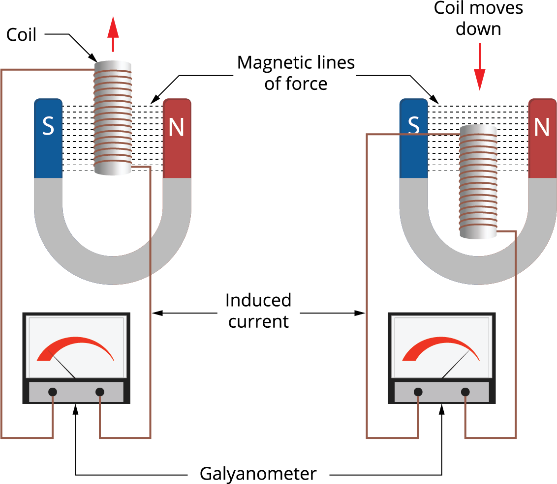
Faraday's Classic Magnet-and-Coil Experiment
A coil is connected to a galvanometer.
A bar magnet is moved toward the coil.
The changing magnetic flux induces an EMF, causing current to flow.
If the magnet stops:
current falls to zero
If the magnet is pulled away:
the current reverses direction
If the magnet is moved faster:
the induced EMF becomes larger
Faraday's experiments established that it is the change in magnetic flux, rather than simply the presence of a magnetic field, that produces induction.
Worked Example 1: Single Loop
The magnetic flux through a single loop changes from:
0.080 Wb
to:
0.020 Wb
in:
0.30 s
First calculate the change in flux:
ΔΦ = 0.020 − 0.080
ΔΦ = −0.060 Wb
For the magnitude:
|ΔΦ| = 0.060 Wb
Use Faraday's Law:
|ε| = N|ΔΦ|/Δt
For one loop:
N = 1
Therefore:
|ε| = (1)(0.060)/0.30
|ε| = 0.20 V
The induced EMF has a magnitude of:
0.20 V
Worked Example 2: Coil with Many Turns
A coil has:
N = 250 turns
The flux through each turn changes by:
0.012 Wb
in:
0.40 s
Use:
|ε| = N|ΔΦ|/Δt
Substitute:
|ε| = 250(0.012)/0.40
|ε| = 7.5 V
Answer:
7.5 V
Notice how the large number of turns increases the induced EMF.
Worked Example 3: Faster Change
A 100-turn coil experiences a flux change of:
0.020 Wb
Case A: change occurs in 2.0 s
|ε| = 100(0.020)/2.0
|ε| = 1.0 V
Case B: change occurs in 0.50 s
|ε| = 100(0.020)/0.50
|ε| = 4.0 V
The same flux change produced four times the EMF because it happened four times faster.
Lenz's Law
Faraday's Law tells us the size of the induced EMF.
Lenz's Law helps us determine its direction.
Lenz's Law states:
The induced current flows in a direction that creates a magnetic field opposing the change in magnetic flux that caused it.
This does not mean that the induced field always opposes the original magnetic field.
It opposes the change in magnetic flux.

Opposing the Change
This wording is extremely important.
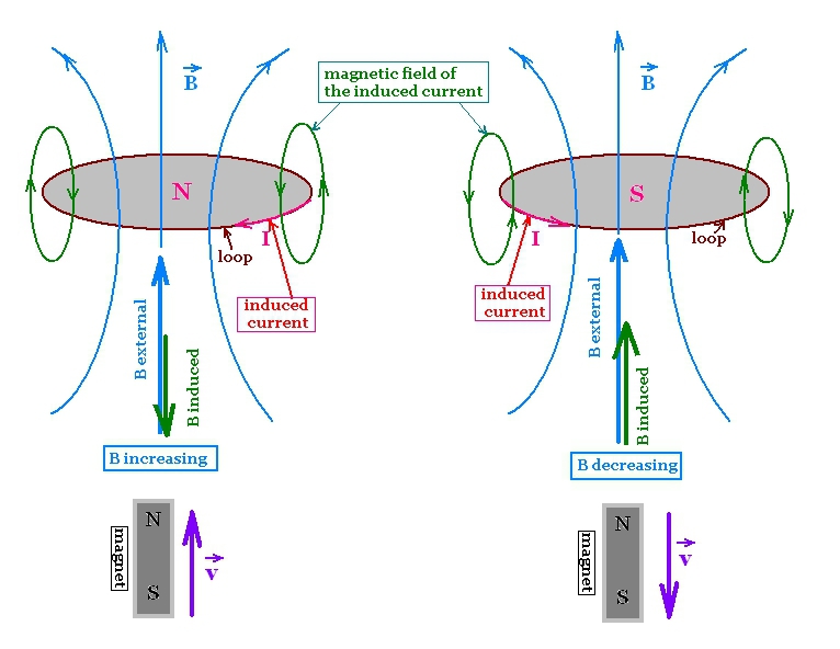
Consider an external magnetic field through a loop.
External field increasing
The induced magnetic field points in the opposite direction.
It tries to oppose the increase.
External field decreasing
The induced magnetic field points in the same direction as the original field.
It tries to oppose the decrease.
So Lenz's Law acts as though the circuit tries to resist the change in flux, not simply oppose every magnetic field.
Why Does the Induced Current Oppose the Change?
Lenz's Law is closely connected to the:
conservation of energy
Suppose a magnet approaching a coil produced an induced magnetic field that helped pull the magnet in faster.
Then:
- motion would create current
- current would pull the magnet faster
- faster motion would create even more current
- energy would continually increase without an external energy source
That would violate conservation of energy.
Instead, the induced magnetic field resists the change that produced it. Mechanical work must be done to keep moving the magnet, and that energy can be transferred into electrical and thermal energy.
Magnet Approaching a Coil
Suppose the north pole of a magnet moves toward a coil.
The magnetic flux through the coil increases.
The coil responds by creating a magnetic field that opposes this increase.
Therefore the near face of the coil becomes:
a north pole
The approaching north pole is therefore:
repelled

This opposition does not prevent the magnet from moving.
You can still push it toward the coil, but you must perform work against the magnetic resistance.
Magnet Moving Away
Now suppose the north pole moves away from the coil.
The magnetic flux through the coil decreases.
The induced current creates a magnetic field that tries to maintain the original flux.
The near face of the coil therefore becomes:
a south pole
The receding north pole is:
attracted
The coil is again opposing the change — this time it opposes the decrease in flux.
Lenz's Law and the Minus Sign
Faraday's Law is:
ε = −N ΔΦ/Δt
The minus sign does not mean the EMF is simply "negative."
It represents the directional relationship described by Lenz's Law:
the induced effect opposes the change in magnetic flux.
When only the magnitude is required, we often use:
|ε| = N|ΔΦ|/Δt
and determine the direction separately using Lenz's Law.
Determining Induced Current Direction
A reliable method uses two ideas:
Lenz's Law
and:
the right-hand grip rule
The steps are:
- Determine the direction of the external magnetic field through the loop.
- Decide whether the magnetic flux is increasing or decreasing.
- Determine which direction the induced magnetic field must point to oppose that change.
- Use the right-hand grip rule to determine the current direction.
This is essentially the problem-solving method recommended by OpenStax.
Right-Hand Grip Rule for a Current Loop
Curl the fingers of your right hand in the direction of conventional current around the loop.
Your thumb points in the direction of the magnetic field through the centre of the loop.

Another useful shortcut when looking directly at one face of a coil:
anticlockwise current → that face behaves as a north pole
clockwise current → that face behaves as a south pole
Example 1: Increasing Field Into the Page
Suppose the external magnetic field points:
into the page
and its strength is increasing.
Lenz's Law says the induced field must oppose the increase.
Therefore the induced field points:
out of the page
Use the right-hand rule.
To create a field out of the page, the current must flow:
anticlockwise
So:
increasing field into page → anticlockwise induced current
Example 2: Decreasing Field Into the Page
Now the field still points into the page, but its strength is decreasing.
The loop tries to prevent the decrease.
Therefore the induced field must also point:
into the page
Using the right-hand rule:
clockwise current
creates a field into the page.
So:
decreasing field into page → clockwise induced current
Example 3: Increasing Field Out of the Page
External flux:
out of page and increasing
The induced field must point:
into the page
Therefore:
clockwise induced current
Example 4: Decreasing Field Out of the Page
External flux:
out of page and decreasing
The induced field must try to maintain it:
out of the page
Therefore:
anticlockwise induced current
Direction Summary
| External Flux | What Is Happening? | Induced Field | Induced Current |
|---|---|---|---|
| Into page | Increasing | Out of page | Anticlockwise |
| Into page | Decreasing | Into page | Clockwise |
| Out of page | Increasing | Into page | Clockwise |
| Out of page | Decreasing | Out of page | Anticlockwise |
This table is a useful checking tool, but understanding the reasoning is much more valuable than memorising it.
Approaching North Pole: Direction Method
Consider a north pole approaching a loop.
Step 1:
The magnetic field from the north pole points away from the magnet and through the loop.
Step 2:
The magnet is approaching, so that flux is:
increasing
Step 3:
The induced field must oppose that increase.
Step 4:
The near face of the coil must become:
north
Step 5:
Viewed from the magnet side, a north face requires:
anticlockwise current
Approaching South Pole
Now reverse the magnet so the south pole approaches.
The direction of the external field through the coil reverses.
The induced field must again oppose the increase in flux.
Therefore the near side of the coil becomes:
south
Viewed from the magnet side, this requires:
clockwise current
So reversing the magnet reverses the induced current.
Pulling the Magnet Away Reverses the Current
If the direction of motion reverses:
increasing flux becomes decreasing flux
or vice versa.
Lenz's Law then requires the induced magnetic field to reverse.
Therefore:
the induced current reverses direction
This matches what is observed in magnet-and-galvanometer experiments.
Magnetic Flux and EMF Graphs
Faraday's Law says induced EMF depends on the slope of a magnetic-flux-versus-time graph.
If flux changes rapidly:
steep flux graph → large EMF
If flux is constant:
horizontal flux graph → zero EMF
If the direction of the flux change reverses:
the sign of the EMF reverses
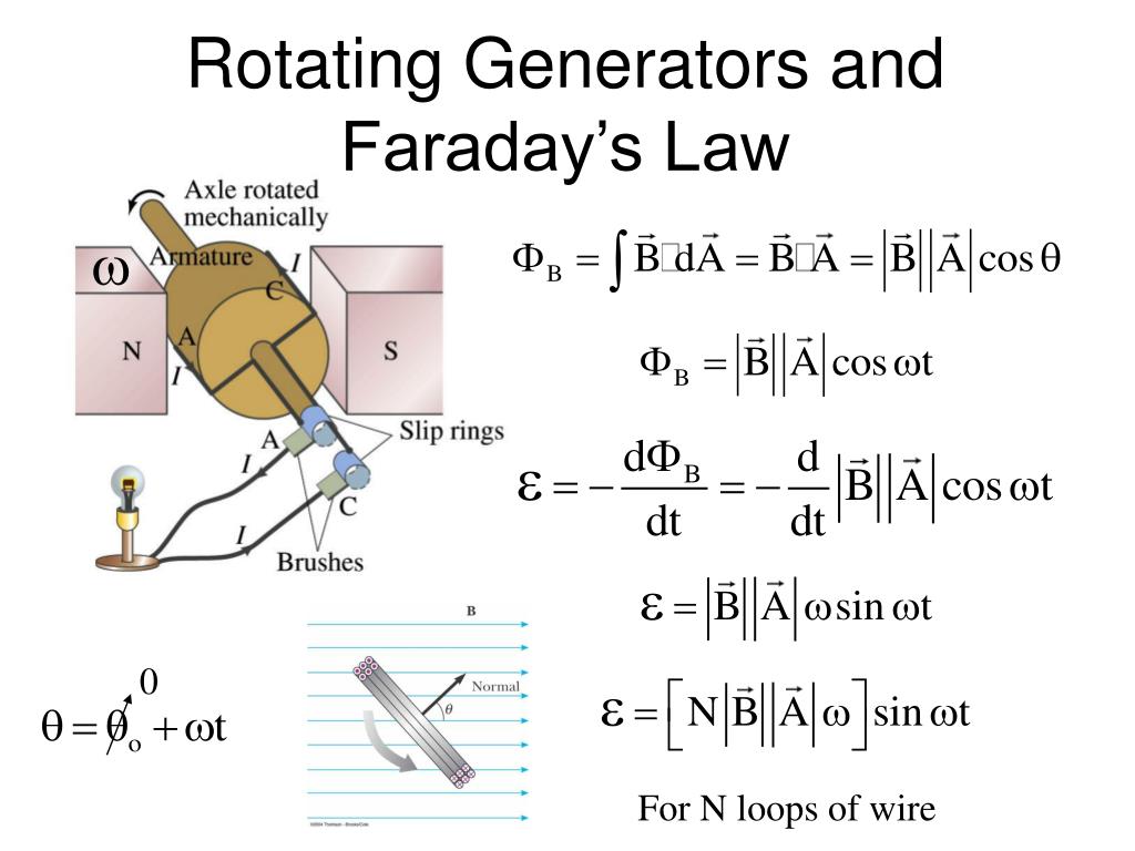
Flux and EMF in a Rotating Generator
In a simple AC generator, a coil rotates in a magnetic field.
The magnetic flux varies approximately as:
Φ = BA cos θ
As the coil rotates:
θ changes continuously
so flux changes continuously.
Faraday's Law therefore produces an alternating EMF.
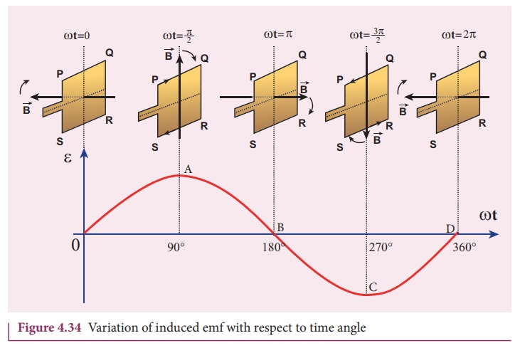
The induced EMF is greatest when the magnetic flux is changing most rapidly, not when the flux itself is greatest.
Maximum Flux Does Not Mean Maximum EMF
This is an important point.
When magnetic flux reaches its maximum value, its graph is momentarily flat.
That means:
rate of change of flux = 0
Therefore:
induced EMF = 0
When the flux passes through zero, it can be changing most rapidly.
At that moment:
induced EMF is maximum
Worked Example 4: Finding the Time Interval
A 50-turn coil experiences a flux change of:
0.030 Wb
An average EMF of:
3.0 V
is induced.
Find the time interval.
Use:
|ε| = N|ΔΦ|/Δt
Rearrange:
Δt = N|ΔΦ|/|ε|
Substitute:
Δt = 50(0.030)/3.0
Δt = 0.50 s
Worked Example 5: Finding Flux Change
A 200-turn coil produces an average EMF of:
12 V
for:
0.25 s
Find the change in flux through each turn.
Use:
|ε| = N|ΔΦ|/Δt
Rearrange:
|ΔΦ| = |ε|Δt/N
Substitute:
|ΔΦ| = (12)(0.25)/200
|ΔΦ| = 0.015 Wb
Worked Example 6: Changing Magnetic Field
A 100-turn coil has an area of:
0.020 m²
The magnetic field passes perpendicular to the coil and increases from:
0.10 T
to:
0.40 T
in:
0.50 s
Since the field is perpendicular to the surface:
Φ = BA
Change in magnetic field:
ΔB = 0.40 − 0.10
ΔB = 0.30 T
Change in flux through one turn:
ΔΦ = AΔB
ΔΦ = (0.020)(0.30)
ΔΦ = 0.0060 Wb
Now use Faraday's Law:
|ε| = 100(0.0060)/0.50
|ε| = 1.2 V
Worked Example 7: Rotating a Coil
A 40-turn coil has an area of:
0.050 m²
in a magnetic field of:
0.20 T
Initially, the normal to the coil is parallel to the field.
The coil rotates until its normal is perpendicular to the field.
Initial flux:
Φ₁ = BA cos 0°
Φ₁ = (0.20)(0.050)
Φ₁ = 0.010 Wb
Final flux:
Φ₂ = BA cos 90°
Φ₂ = 0
Therefore:
|ΔΦ| = 0.010 Wb
If the rotation occurs in:
0.20 s
then:
|ε| = 40(0.010)/0.20
|ε| = 2.0 V
Why Number of Turns Matters
Suppose two coils experience exactly the same magnetic flux change.
Coil A:
20 turns
Coil B:
200 turns
The rate of change per turn is the same.
But Coil B has ten times as many turns.
Therefore:
Coil B produces ten times the EMF
according to:
ε = −NΔΦ/Δt
Faraday's Law in Transformers
A transformer has:
- a primary coil
- an iron core
- a secondary coil
Alternating current in the primary produces a changing magnetic flux in the core.
That changing flux passes through the secondary coil.
Faraday's Law then produces an induced EMF in the secondary.
This is one of the most important practical applications of Faraday's Law.
Faraday's Law in Generators
A generator changes magnetic flux by rotating a coil or magnet.
Mechanical energy causes the rotation.
The rotation changes magnetic flux.
Faraday's Law produces an EMF.
So the energy pathway is approximately:
mechanical energy
→ changing magnetic flux
→ electrical energy
Faraday's Law in Wind Turbines
Wind turns the blades of a turbine.
The blades drive a shaft.
The shaft turns part of a generator.
Inside the generator, magnets and conducting coils move relative to one another.
This changes magnetic flux and induces an EMF.
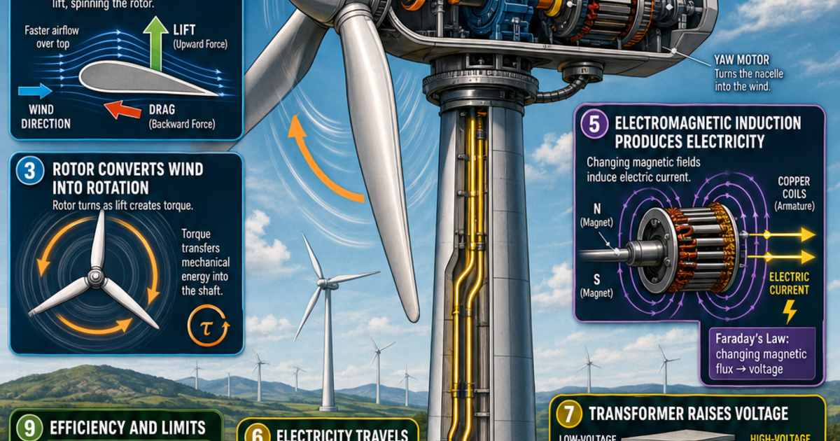
Faraday's Law is therefore directly involved in converting wind's kinetic energy into electrical energy.
Lenz's Law in Generators
Lenz's Law explains why turning a generator requires effort.
As the generator produces current, the induced current creates its own magnetic field.
That field opposes the change that caused it.
Therefore the generator resists being turned.
The greater the electrical power being produced, the more mechanical input is generally required.
This is another consequence of conservation of energy.
A Useful Four-Step Lenz's Law Method
For almost any direction question, use:
Step 1: Find the external field direction
Is it into the page, out of the page, left, right, etc.?
Step 2: Decide whether the flux is increasing or decreasing
Ask what is changing.
Step 3: Find the required induced magnetic field
The induced field must oppose the change.
Step 4: Use the right-hand rule
Convert the required induced magnetic field into a current direction.
This approach is much more reliable than trying to memorize individual cases.
Example Direction Problem
A magnetic field points out of the page through a circular loop.
The field strength is increasing.
Step 1
External field:
out of page
Step 2
Flux:
increasing
Step 3
The induced field must oppose the increase:
into the page
Step 4
Right-hand rule:
clockwise current
Answer:
The induced current flows clockwise.
Another Direction Problem
A magnetic field points out of the page and is becoming weaker.
Step 1
External field:
out of page
Step 2
Flux:
decreasing
Step 3
The induced field tries to maintain the flux:
out of page
Step 4
Right-hand rule:
anticlockwise current
Answer:
The induced current flows anticlockwise.
What If the Circuit Is Open?
A changing magnetic flux can still induce an:
EMF
even if the circuit is open.
But without a complete conducting path:
no continuous current flows
This is why it is more accurate to say Faraday's Law describes an induced EMF, rather than automatically describing an induced current.
Common Misconception: More Flux Means More EMF
Not necessarily.
A coil may have a very large but constant magnetic flux.
Then:
ΔΦ = 0
so:
ε = 0
It is the change in flux per unit time, not simply the flux itself, that determines induced EMF.
Common Misconception: Lenz's Law Opposes the Magnetic Field
Not always.
Lenz's Law opposes:
the change in flux
If an external magnetic field is decreasing, the induced field can point in the same direction as the external field in an attempt to maintain the flux.
Common Misconception: The Induced Current Stops the Change
Lenz's Law does not mean the change cannot happen.
You can still:
- push the magnet into the coil
- pull it out
- rotate the generator
- change the magnetic field
The induced effect simply acts in a direction that resists the change.
External work can overcome that resistance.
Common Misconception: Faster Magnet Means More Magnetic Flux
Moving the magnet faster does not necessarily change the total amount of flux change.
It changes how quickly that flux change occurs.
For example:
Same:
ΔΦ
but smaller:
Δt
means larger:
ΔΦ/Δt
and therefore larger:
EMF
That distinction is central to Faraday's Law.
Common Misconception: The Minus Sign Is Used in Every Numerical Calculation
If the question asks only for the magnitude of induced EMF, use:
|ε| = N|ΔΦ|/Δt
Then report the positive magnitude.
Use Lenz's Law to determine direction separately.
The negative sign in the full equation represents direction, not a negative amount of voltage in an absolute sense.
Faraday vs Lenz
| Law | Main Question Answered |
|---|---|
| Faraday's Law | How large is the induced EMF? |
| Lenz's Law | In which direction is the induced effect? |
Faraday:
|ε| = N|ΔΦ|/Δt
Lenz:
induced effect opposes the change in magnetic flux
Together they give both:
magnitude + direction
A Complete Induction Explanation
Suppose a magnet moves rapidly toward a coil.
A strong explanation would be:
"As the magnet approaches, the magnetic flux through the coil increases. According to Faraday's Law, this changing flux induces an EMF, and because the flux is changing rapidly, the induced EMF is relatively large. According to Lenz's Law, the induced current produces a magnetic field that opposes the increase in flux, so the near side of the coil forms the same magnetic pole as the approaching pole and repels it."
This combines:
- magnetic flux
- rate of change
- Faraday's Law
- Lenz's Law
- induced magnetic field
- current direction
- energy conservation
Did You Know?
Michael Faraday's experiments in 1831 showed that changing magnetic fields could produce electrical effects. Heinrich Lenz later clearly formulated the rule governing the direction of the induced current. Their work became fundamental to generators, transformers, electric power systems, microphones, induction cookers, and many other technologies.
Key Terms
Faraday's Law – The induced EMF is proportional to the rate of change of magnetic flux linkage.
Lenz's Law – The induced current produces a magnetic field that opposes the change in magnetic flux that caused it.
Magnetic flux (Φ) – Measure of magnetic field passing through a surface.
Flux linkage (NΦ) – Magnetic flux multiplied by the number of turns in a coil.
Induced EMF – Voltage produced by changing magnetic flux.
Induced current – Current produced when an induced EMF acts in a complete circuit.
Rate of change – How quickly a quantity changes with time.
Right-hand grip rule – Method for relating current direction in a loop to the direction of its magnetic field.
Conservation of energy – Principle that energy cannot be created or destroyed, only transferred or transformed.
Key Takeaways
- Faraday's Law states that induced EMF depends on the rate of change of magnetic flux linkage.
- For a coil:
ε = −NΔΦ/Δt
- More coil turns generally produce a larger induced EMF.
- A larger flux change produces a larger EMF if the time remains constant.
- A faster flux change produces a larger EMF.
- Constant magnetic flux produces no continuous induced EMF.
- Magnetic flux can change because B, A, or θ changes.
- Lenz's Law determines the direction of the induced effect.
- The induced magnetic field opposes the change in magnetic flux, not necessarily the original magnetic field.
- Increasing flux produces an induced field that acts against the increase.
- Decreasing flux produces an induced field that acts against the decrease.
- Use the right-hand rule to convert induced field direction into induced current direction.
- The minus sign in Faraday's Law represents Lenz's Law.
- Lenz's Law is consistent with conservation of energy.
- Faster magnet motion generally produces a greater induced EMF because the flux changes more rapidly.
- When a magnet reverses direction, the induced current reverses.
- When the magnet stops relative to the coil, the induced EMF falls to zero.
- Generators and transformers are major applications of Faraday's Law.
- A reliable direction strategy is:
external field → increasing or decreasing flux → required induced field → right-hand rule → induced current direction.
4. Factors Affecting Induced EMF
Learning outcomes
- I can identify variables that influence induced EMF.
- I can explain how coil turns affect induced voltage.
- I can describe how magnetic field strength changes induction.
- I can explain how conductor speed affects induced EMF.
- I can predict how changing experimental conditions alters induced voltage.
5. Practical Demonstrations of Induction
Learning outcomes
- I can explain what happens during common induction demonstrations.
- I can describe how moving magnets induce current in coils.
- I can interpret observations from induction experiments.
- I can relate demonstrations to Faraday's and Lenz's Laws.
- I can explain real-world examples that operate using electromagnetic induction.