Advanced Vector Geometry
| Site: | Young Education |
| Cours: | Vectors and Matrices |
| Livre: | Advanced Vector Geometry |
| Imprimé par: | Guest user |
| Date: | lundi 9 novembre 2026, 16:41 |
1. Dot Product
Learning outcomes
- I can calculate the dot product of two vectors.
- I can determine the angle between vectors.
- I can identify perpendicular vectors.
- I can solve projection problems.
- I can interpret the geometric meaning of the dot product.
Dot Product
Introduction to the Dot Product
Vectors are mathematical quantities that have both magnitude and direction. They are used to represent displacement, velocity, acceleration, force, and many other physical quantities.
When working with vectors, we often need to determine how two vectors are related. For example:
-
Do two forces act in the same direction?
-
Are two directions perpendicular?
-
What angle separates two vectors?
-
How much of one vector acts in the direction of another?
-
How much work is performed by a force acting at an angle?
The dot product, also called the scalar product, is a mathematical operation that helps answer these questions.
Unlike vector addition, which produces another vector, the dot product produces a single number called a scalar.
The dot product connects the components of vectors with their magnitudes and the angle between them. This makes it useful in geometry, physics, engineering, navigation, and computer graphics.
Understanding the Dot Product
The dot product of two vectors A and B is written:
A · B
The dot symbol indicates the dot product operation.
The result is a scalar, not a vector.
For example:
A · B = 12
This means the dot product of vectors A and B is 12.
What Does the Dot Product Tell Us?
The dot product measures how strongly two vectors point in the same direction, taking their magnitudes into account.
-
A positive dot product indicates that the angle between the nonzero vectors is acute.
-
A zero dot product indicates that two nonzero vectors are perpendicular.
-
A negative dot product indicates that the angle between the nonzero vectors is obtuse.
The magnitude of the result also depends on the lengths of the vectors.
A larger positive dot product does not necessarily mean a smaller angle unless the vector magnitudes are held constant.
Calculating the Dot Product Using Components
Vectors can be represented using horizontal and vertical components.
In two dimensions:
A = (Aₓ, Aᵧ)
B = (Bₓ, Bᵧ)
The dot product is calculated by multiplying corresponding components and adding the results.
A · B = AₓBₓ + AᵧBᵧ
Worked Example: Two-Dimensional Dot Product
Given:
A = (3, 4)
B = (2, 5)
Calculate A · B.
Step 1: Write the formula
A · B = AₓBₓ + AᵧBᵧ
Step 2: Substitute the components
A · B = (3)(2) + (4)(5)
Step 3: Multiply
A · B = 6 + 20
Step 4: Add
A · B = 26
The dot product is 26.
Because the result is positive, the angle between the vectors is acute.
Worked Example: Negative Components
Given:
A = (−2, 5)
B = (4, −3)
Calculate A · B.
A · B = (−2)(4) + (5)(−3)
A · B = −8 − 15
A · B = −23
The negative result indicates that the angle between the vectors is greater than 90°.
Worked Example: Zero Dot Product
Given:
A = (3, 4)
B = (−4, 3)
Calculate A · B.
A · B = (3)(−4) + (4)(3)
A · B = −12 + 12
A · B = 0
Since both vectors are nonzero, they are perpendicular.
Dot Product in Three Dimensions
The dot product can also be calculated for three-dimensional vectors.
Given:
A = (Aₓ, Aᵧ, Aᵤ)
B = (Bₓ, Bᵧ, Bᵤ)
where the third components represent the z-direction, the formula is:
A · B = AₓBₓ + AᵧBᵧ + AᵤBᵤ
More conventionally, writing the components as (Aₓ, Aᵧ, A_z) and (Bₓ, Bᵧ, B_z):
A · B = AₓBₓ + AᵧBᵧ + A_zB_z
Worked Example: Three-Dimensional Dot Product
Given:
A = (2, −1, 3)
B = (4, 5, −2)
Calculate A · B.
Step 1: Write the formula
A · B = AₓBₓ + AᵧBᵧ + A_zB_z
Step 2: Substitute
A · B = (2)(4) + (−1)(5) + (3)(−2)
Step 3: Multiply
A · B = 8 − 5 − 6
Step 4: Add
A · B = −3
The dot product is −3.
The vectors form an obtuse angle.
Important Observation
The same principle applies in two, three, or more dimensions:
Multiply corresponding components and add the products.
The Geometric Definition of the Dot Product
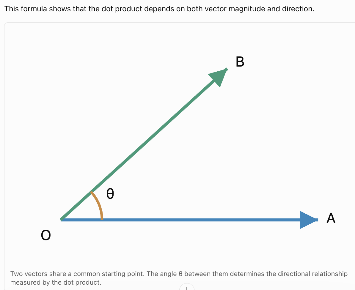
The dot product can also be calculated using the magnitudes of two vectors and the angle between them.
The geometric formula is:
A · B = |A||B| cos θ
where:
-
A · B is the dot product.
-
|A| is the magnitude of vector A.
-
|B| is the magnitude of vector B.
-
θ is the angle between the vectors.
-
cos θ is the cosine of the angle.
The angle θ is normally taken between 0° and 180°.
How the Angle Affects the Dot Product
The cosine function determines whether the dot product is positive, zero, or negative.
|
Angle θ |
cos θ |
Dot product |
|---|---|---|
|
0° |
1 |
Positive maximum for fixed magnitudes |
|
30° |
≈ 0.866 |
Positive |
|
60° |
0.5 |
Positive |
|
90° |
0 |
Zero |
|
120° |
−0.5 |
Negative |
|
150° |
≈ −0.866 |
Negative |
|
180° |
−1 |
Negative minimum for fixed magnitudes |
Vectors Pointing in the Same Direction
When θ = 0°:
cos 0° = 1
Therefore:
A · B = |A||B|
The dot product is as large as possible for the given magnitudes.
Perpendicular Vectors
When θ = 90°:
cos 90° = 0
Therefore:
A · B = 0
The dot product is zero.
Vectors Pointing in Opposite Directions
When θ = 180°:
cos 180° = −1
Therefore:
A · B = −|A||B|
The dot product is as negative as possible for the given magnitudes.
Calculating the Dot Product from Magnitudes and Angles
Worked Example: Acute Angle
Two vectors have magnitudes:
|A| = 6
|B| = 8
The angle between them is 60°.
Calculate the dot product.
Step 1: Write the formula
A · B = |A||B| cos θ
Step 2: Substitute
A · B = (6)(8) cos 60°
Step 3: Evaluate the cosine
cos 60° = 0.5
Step 4: Calculate
A · B = 48(0.5)
A · B = 24
Worked Example: Obtuse Angle
Two vectors have magnitudes:
|A| = 5
|B| = 10
The angle between them is 120°.
A · B = (5)(10) cos 120°
Since:
cos 120° = −0.5
A · B = 50(−0.5)
A · B = −25
The negative result is consistent with the obtuse angle.
Calculating Vector Magnitudes
To determine the angle between vectors, we must often calculate their magnitudes first.
For a two-dimensional vector:
A = (Aₓ, Aᵧ)
its magnitude is:
|A| = √(Aₓ² + Aᵧ²)
For a three-dimensional vector:
A = (Aₓ, Aᵧ, A_z)
its magnitude is:
|A| = √(Aₓ² + Aᵧ² + A_z²)
Worked Example
Find the magnitude of:
A = (6, 8)
|A| = √(6² + 8²)
|A| = √(36 + 64)
|A| = √100
|A| = 10
Three-Dimensional Example
Find the magnitude of:
B = (2, −3, 6)
|B| = √(2² + (−3)² + 6²)
|B| = √(4 + 9 + 36)
|B| = √49
|B| = 7
Finding the Angle Between Two Vectors
The geometric dot product formula can be rearranged to determine the angle between vectors.
Starting with:
A · B = |A||B| cos θ
Divide by the product of the magnitudes:
cos θ = (A · B)/(|A||B|)
Take the inverse cosine:
θ = cos⁻¹[(A · B)/(|A||B|)]
This formula applies when both vectors are nonzero.
Worked Example: Finding an Acute Angle
Given:
A = (1, 2)
B = (3, 1)
Find the angle between the vectors.
Step 1: Calculate the dot product
A · B = (1)(3) + (2)(1)
A · B = 3 + 2
A · B = 5
Step 2: Find the magnitude of A
|A| = √(1² + 2²)
|A| = √5
Step 3: Find the magnitude of B
|B| = √(3² + 1²)
|B| = √10
Step 4: Substitute
cos θ = 5/(√5 × √10)
cos θ = 5/√50
cos θ ≈ 0.7071
Step 5: Take the inverse cosine
θ = cos⁻¹(0.7071)
θ = 45°
Interpretation
The vectors form an angle of 45°.
Since the dot product is positive, an acute angle is expected.
Worked Example: Finding an Obtuse Angle
Given:
A = (2, 1)
B = (−3, 2)
Find the angle between the vectors.
Step 1: Calculate the dot product
A · B = (2)(−3) + (1)(2)
A · B = −6 + 2
A · B = −4
Step 2: Calculate the magnitudes
|A| = √(2² + 1²) = √5
|B| = √((−3)² + 2²) = √13
Step 3: Substitute
cos θ = −4/(√5 × √13)
cos θ = −4/√65
cos θ ≈ −0.4961
Step 4: Calculate the angle
θ = cos⁻¹(−0.4961)
θ ≈ 119.7°
Reasonableness Check
The dot product is negative.
Therefore, the angle should be greater than 90°.
The calculated angle of approximately 119.7° is reasonable.
Identifying Perpendicular Vectors
Two vectors are perpendicular when they meet at an angle of 90°.
For two nonzero vectors:
A · B = 0 if and only if A and B are perpendicular.
This is one of the most useful applications of the dot product.
Worked Example: Testing Perpendicularity
Given:
A = (4, 3)
B = (−3, 4)
Determine whether the vectors are perpendicular.
Step 1: Calculate the dot product
A · B = (4)(−3) + (3)(4)
A · B = −12 + 12
A · B = 0
Step 2: Interpret
Both vectors are nonzero, and their dot product is zero.
Therefore:
A and B are perpendicular.
Worked Example: Vectors That Are Not Perpendicular
Given:
A = (5, 2)
B = (3, −4)
A · B = (5)(3) + (2)(−4)
A · B = 15 − 8
A · B = 7
Since the dot product is not zero, the vectors are not perpendicular.
Finding an Unknown Component
The perpendicularity condition can be used to solve algebraic problems.
Worked Example
Given:
A = (3, 4)
B = (x, 6)
Find x if the vectors are perpendicular.
Step 1: Apply the perpendicularity condition
A · B = 0
Step 2: Substitute
3x + 4(6) = 0
Step 3: Simplify
3x + 24 = 0
Step 4: Solve
3x = −24
x = −8
Verification
B = (−8, 6)
A · B = (3)(−8) + (4)(6)
A · B = −24 + 24
A · B = 0
The vectors are perpendicular.
Orthogonal Vectors
Vectors with a dot product of zero are called orthogonal vectors.
For nonzero vectors, orthogonal means perpendicular.
The term orthogonal is particularly common in linear algebra and higher-dimensional vector spaces.
Example
A = (1, 0, 0)
B = (0, 1, 0)
A · B = (1)(0) + (0)(1) + (0)(0)
A · B = 0
The vectors are orthogonal.
The Zero Vector
The zero vector has all components equal to zero.
For example:
O = (0, 0)
Its dot product with every vector is zero.
However, the zero vector has no defined direction, so an angle between the zero vector and another vector is undefined.
This is why angle calculations require nonzero vectors.
Understanding Vector Projection
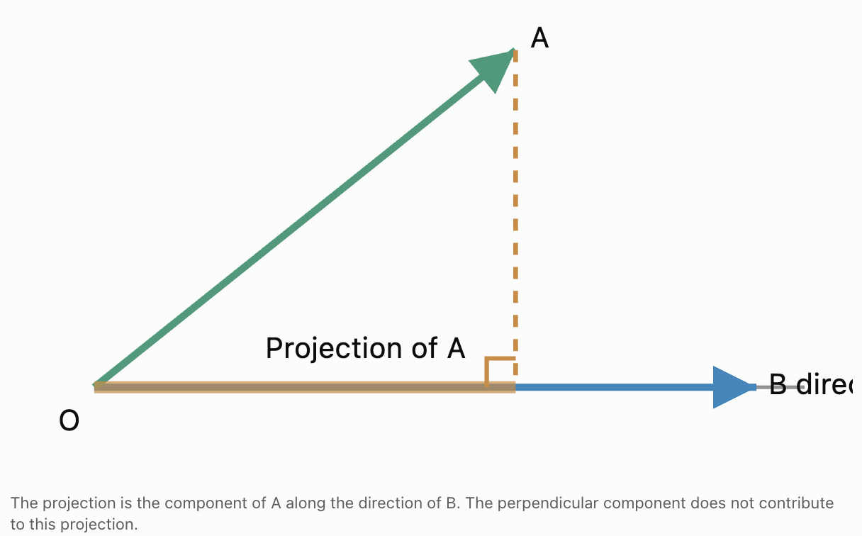
A vector projection describes the part of one vector that acts along the direction of another vector.
Imagine shining a light perpendicular to a line. The shadow of a vector onto that line represents its projection.
Projection is useful when a vector must be separated into components acting along particular directions.
Examples include:
- Finding the component of a force along a slope.
- Determining motion in a particular direction.
- Calculating work done by a force.
- Analysing velocities.
- Resolving vectors in engineering.
Scalar Projection
The scalar projection of A onto B gives the signed length of the component of A in the direction of B.
The formula is:
Scalar projection of A onto B = (A · B)/|B|
It can also be written as:
|A| cos θ
The scalar projection may be positive, negative, or zero.
Worked Example
Given:
A = (6, 8)
B = (1, 0)
Find the scalar projection of A onto B.
Step 1: Calculate the dot product
A · B = (6)(1) + (8)(0)
A · B = 6
Step 2: Calculate the magnitude of B
|B| = √(1² + 0²)
|B| = 1
Step 3: Apply the formula
Scalar projection = 6/1
Scalar projection = 6
Interpretation
The component of A in the positive horizontal direction is 6 units.
Vector Projection
The vector projection gives both the magnitude and direction of the component.
The formula for the projection of A onto nonzero B is:
proj_B(A) = [(A · B)/|B|²]B
Since:
|B|² = B · B
the formula may also be written:
proj_B(A) = [(A · B)/(B · B)]B
Worked Example: Vector Projection
Given:
A = (4, 3)
B = (2, 0)
Find the projection of A onto B.
Step 1: Calculate the dot product
A · B = (4)(2) + (3)(0)
A · B = 8
Step 2: Calculate |B|²
|B|² = 2² + 0²
|B|² = 4
Step 3: Apply the formula
proj_B(A) = (8/4)(2, 0)
Step 4: Simplify
proj_B(A) = 2(2, 0)
proj_B(A) = (4, 0)
Interpretation
The projection of A onto B is the horizontal component of A.
The original vector is:
A = (4, 3)
Its horizontal projection is:
(4, 0)
The remaining perpendicular component is:
(0, 3)
Worked Example: Projection onto a Diagonal Vector
Given:
A = (3, 4)
B = (1, 1)
Find the vector projection of A onto B.
Step 1: Calculate A · B
A · B = (3)(1) + (4)(1)
A · B = 7
Step 2: Calculate |B|²
|B|² = 1² + 1²
|B|² = 2
Step 3: Apply the formula
proj_B(A) = (7/2)(1, 1)
Step 4: Multiply
proj_B(A) = (3.5, 3.5)
Verification
The remaining component is:
A − proj_B(A)
= (3, 4) − (3.5, 3.5)
= (−0.5, 0.5)
Check whether this component is perpendicular to B:
(−0.5, 0.5) · (1, 1)
= −0.5 + 0.5
= 0
Therefore, the remaining component is perpendicular to B, confirming that the projection is correct.
Decomposing a Vector into Parallel and Perpendicular Components
Any vector A can be separated into:
-
A component parallel to a nonzero vector B.
-
A component perpendicular to B.
The parallel component is:
A_parallel = proj_B(A)
The perpendicular component is:
A_perpendicular = A − proj_B(A)
Therefore:
A = A_parallel + A_perpendicular
Worked Example
Given:
A = (5, 4)
B = (3, 0)
Find the parallel and perpendicular components of A relative to B.
Step 1: Calculate the dot product
A · B = (5)(3) + (4)(0)
A · B = 15
Step 2: Calculate |B|²
|B|² = 3² = 9
Step 3: Find the parallel component
A_parallel = (15/9)(3, 0)
A_parallel = (5, 0)
Step 4: Find the perpendicular component
A_perpendicular = (5, 4) − (5, 0)
A_perpendicular = (0, 4)
Final Answer
Parallel component = (5, 0)
Perpendicular component = (0, 4)
Verification
(5, 0) + (0, 4) = (5, 4)
The original vector has been reconstructed.
Properties of the Dot Product
The dot product has several important algebraic properties.
Commutative Property
A · B = B · A
The order of the vectors does not change the result.
Example:
A = (2, 3)
B = (4, 5)
A · B = 2(4) + 3(5) = 23
B · A = 4(2) + 5(3) = 23
Both results are equal.
Distributive Property
A · (B + C) = A · B + A · C
This allows dot products to be expanded across vector addition.
Scalar Multiplication
(kA) · B = k(A · B)
where k is a scalar.
Dot Product of a Vector with Itself
A · A = |A|²
For example:
A = (3, 4)
A · A = 3² + 4²
A · A = 25
Therefore:
|A| = √25 = 5
Non-Negativity
For every vector A:
A · A ≥ 0
The result equals zero only when A is the zero vector.
Important Observation
Although the dot product is commutative, vector projection is generally not.
In general:
proj_B(A) ≠ proj_A(B)
The direction of projection matters.
The Dot Product and the Law of Cosines
The dot product is closely related to the Law of Cosines.
For vectors A and B:
|A − B|² = (A − B) · (A − B)
Expanding:
|A − B|² = A · A − 2(A · B) + B · B
Since:
A · A = |A|²
B · B = |B|²
and:
A · B = |A||B| cos θ
we obtain:
|A − B|² = |A|² + |B|² − 2|A||B| cos θ
This is the vector form of the Law of Cosines.
Why This Matters
The Law of Cosines generalises the Pythagorean Theorem.
When θ = 90°:
cos 90° = 0
Therefore:
|A − B|² = |A|² + |B|²
This is the Pythagorean relationship.
The dot product therefore connects vector geometry, trigonometry, and triangle geometry.
Real-World Application: Work Done by a Force
In physics, work is the energy transferred when a force causes displacement.
When the force and displacement are vectors, work is calculated using the dot product.
W = F · s
or:
W = |F||s| cos θ
where:
-
W is work done, measured in joules (J).
-
F is the force vector, measured in newtons (N).
-
s is the displacement vector, measured in metres (m).
-
θ is the angle between force and displacement.
Worked Example: Pulling an Object
A person pulls a box with a force of 50 N at an angle of 30° above the horizontal.
The box moves 8 m horizontally.
Calculate the work done by the pulling force.

Step 1: Identify the Values
|F| = 50 N
|s| = 8 m
θ = 30°
Step 2: Apply the Formula
W = |F||s| cos θ
Step 3: Substitute
W = (50)(8) cos 30°
Step 4: Calculate
W = 400(0.8660)
W ≈ 346.4 J
Interpretation
The pulling force performs approximately 346.4 J of work.
Only the component of the force parallel to the displacement contributes to the work.
The upward component does not contribute to the work in this example because the displacement is horizontal.
Positive, Negative, and Zero Work
The sign of the dot product has a direct physical interpretation.
Positive Work
When the force acts partly in the direction of displacement:
W > 0
The force transfers energy to the object through mechanical work.
Negative Work
When the force acts partly opposite the displacement:
W < 0
For example, friction often performs negative work on a sliding object.
Zero Work
When the force is perpendicular to displacement:
W = 0
For example, the normal force does zero work on an object moving horizontally across a level surface when the normal force is vertical.
Real-World Application: Motion Along a Slope
Vector projection can determine the component of a force acting along an inclined surface.
For an object on a slope inclined at angle θ above the horizontal, the component of its weight parallel to the slope has magnitude:
F_parallel = mg sin θ
The component perpendicular to the slope has magnitude:
F_perpendicular = mg cos θ
These formulas can be derived by projecting the weight vector onto directions parallel and perpendicular to the slope.
Worked Example
A 10 kg object rests on a slope inclined at 30°.
Find the magnitude of the component of gravitational force acting down the slope.
Take:
g = 9.8 m/s²
Step 1: Calculate the Weight
F = mg
F = 10(9.8)
F = 98 N
Step 2: Calculate the Parallel Component
F_parallel = 98 sin 30°
Step 3: Evaluate
sin 30° = 0.5
F_parallel = 98(0.5)
F_parallel = 49 N
Interpretation
The component of gravitational force acting down the slope is 49 N.
The remaining component acts perpendicular to the slope.

Real-World Application: Computer Graphics
Dot products are used in computer graphics to calculate how brightly a surface is illuminated.
A surface receives more direct illumination when its outward normal vector points toward a light source.
The brightness calculation often depends on:
N · L
where:
-
N is a unit vector perpendicular to the surface.
-
L is a unit vector pointing toward the light source.
When both are unit vectors:
N · L = cos θ
Interpretation
-
If N · L = 1, the light points directly along the surface normal.
-
If N · L = 0, the light direction is perpendicular to the normal.
-
If N · L is negative, the light is directed toward the back side of the surface.
In a simple diffuse-lighting model, the illuminated front-facing contribution is proportional to:
max(0, N · L)
This is one reason the dot product is fundamental to three-dimensional graphics and game development.

Real-World Application: Navigation
Dot products can determine whether movement is aligned with a desired direction.
Worked Example
A vehicle has velocity:
v = (12, 5) m/s
The desired direction is represented by:
d = (1, 0)
Calculate the component of velocity in the desired direction.
Step 1: Calculate the Dot Product
v · d = (12)(1) + (5)(0)
v · d = 12
Step 2: Calculate the Magnitude of d
|d| = 1
Step 3: Find the Scalar Projection
Scalar projection = 12/1
Scalar projection = 12 m/s
Interpretation
The vehicle's velocity component in the positive horizontal direction is 12 m/s.
Its total speed is:
|v| = √(12² + 5²)
|v| = √169
|v| = 13 m/s
Therefore, the vehicle travels at 13 m/s overall, but only 12 m/s of that velocity is in the specified horizontal direction.
Choosing the Correct Dot Product Method
Different problems require different forms of the dot product.
| Problem | Method | |---|---| | Calculate a dot product from components | A · B = AₓBₓ + AᵧBᵧ | | Calculate a dot product from magnitudes and angle | A · B = |A||B| cos θ | | Find the angle between nonzero vectors | θ = cos⁻¹[(A · B)/(|A||B|)] | | Test perpendicularity of nonzero vectors | Check whether A · B = 0 | | Find scalar projection onto B | (A · B)/|B| | | Find vector projection onto B | [(A · B)/|B|²]B | | Calculate work done | W = F · s |
Problem-Solving Strategy
-
Identify the vectors and their components.
-
Determine whether magnitudes or angles are given.
-
Decide whether the problem requires a scalar, an angle, or a vector projection.
-
Select the appropriate formula.
-
Substitute carefully, paying attention to negative components.
-
Calculate the result.
-
Check the sign and magnitude for reasonableness.
-
Interpret the result in the original context.
Common Mistakes
Confusing the dot product with vector multiplication
The dot product produces a scalar, not another vector.
Adding corresponding components instead of multiplying them
The dot product requires multiplication of corresponding components followed by addition.
Ignoring negative signs
Negative components can change the sign of the dot product.
Using the wrong angle
The angle must be the angle between the vectors when they are placed tail-to-tail.
Confusing sine and cosine
The geometric dot product formula uses cosine.
Forgetting vector magnitudes when finding angles
The angle formula requires division by the product of both magnitudes.
Using the inverse cosine incorrectly
The inverse cosine function must be used to find an angle from its cosine.
Using radians when degrees are expected
Check the calculator's angle mode.
Assuming a zero dot product always gives a 90° angle
The angle interpretation requires both vectors to be nonzero.
Confusing scalar and vector projection
Scalar projection produces a signed number; vector projection produces a vector.
Using |A|² instead of |B|² in the projection formula
When projecting A onto B, the denominator is |B|².
Assuming projection is commutative
Projecting A onto B is generally different from projecting B onto A.
Ignoring the physical meaning of a negative dot product
In applications such as work, a negative value indicates that the force has a component opposite the displacement.
Rounding intermediate calculations too early
Keep exact values where possible and round only at the final step.
Key Terms
-
Vector: A quantity with magnitude and direction.
-
Scalar: A quantity described by magnitude alone.
-
Dot Product: An operation combining two vectors to produce a scalar.
-
Scalar Product: Another name for the dot product.
-
Vector Component: The amount of a vector acting along a coordinate direction.
-
Magnitude: The length or size of a vector.
-
Direction: The orientation in which a vector points.
-
Angle Between Vectors: The angle formed when two nonzero vectors are placed tail-to-tail.
-
Cosine: A trigonometric function used to relate vector directions.
-
Inverse Cosine: A function used to determine an angle from its cosine value.
-
Perpendicular Vectors: Nonzero vectors forming a 90° angle.
-
Orthogonal Vectors: Vectors whose dot product equals zero.
-
Zero Vector: A vector whose components are all zero.
-
Unit Vector: A vector with magnitude 1.
-
Projection: The component of one vector acting along the direction of another.
-
Scalar Projection: The signed length of a vector's projection onto a specified direction.
-
Vector Projection: A vector representing the component of one vector along another.
-
Parallel Component: The part of a vector acting along a specified direction.
-
Perpendicular Component: The part of a vector acting at 90° to a specified direction.
-
Commutative Property: A property stating that changing the order of two quantities does not change the result.
-
Distributive Property: A property allowing an operation to be distributed across addition.
-
Law of Cosines: A theorem relating the side lengths of a triangle to the cosine of an included angle.
-
Work Done: Energy transferred when a force acts through a displacement.
-
Displacement: A vector describing a change in position.
-
Force: A vector quantity that can change an object's motion.
-
Velocity: A vector describing the rate of change of position.
-
Normal Vector: A vector perpendicular to a surface.
-
Directional Alignment: The extent to which two vectors point in similar directions.
-
Vector Decomposition: Separating a vector into components along specified directions.
Key Takeaways
-
The dot product combines two vectors to produce a scalar.
-
The dot product can be calculated using vector components.
-
In two dimensions, A · B = AₓBₓ + AᵧBᵧ.
-
In three dimensions, A · B = AₓBₓ + AᵧBᵧ + A_zB_z.
-
The geometric formula is A · B = |A||B| cos θ.
-
The dot product depends on vector magnitudes and the angle between them.
-
A positive dot product indicates an acute angle between nonzero vectors.
-
A negative dot product indicates an obtuse angle between nonzero vectors.
-
A zero dot product indicates perpendicularity when both vectors are nonzero.
-
The angle between nonzero vectors can be found using the inverse cosine.
-
The magnitude of a vector can be calculated using the Pythagorean Theorem.
-
Vector projection determines the component of one vector acting along another.
-
Scalar projection produces a signed numerical value.
-
Vector projection produces a vector with direction and magnitude.
-
The dot product is commutative and distributive over vector addition.
-
The dot product of a vector with itself equals the square of its magnitude.
-
The dot product connects vector geometry with the Law of Cosines.
-
In physics, work done by a force is calculated using a dot product.
-
In engineering, projections help resolve forces into useful components.
-
In computer graphics, dot products help determine surface illumination.
-
In navigation, dot products help determine motion along a desired direction.
-
The central skill is using the dot product to calculate directional relationships, determine angles, identify perpendicular vectors, and solve projection problems.
Check Your Understanding
Recall and Understanding
-
Define the dot product and explain why its result is a scalar.
-
State the component formula for the dot product in two and three dimensions.
-
Explain how the sign of the dot product relates to the angle between two nonzero vectors.
-
Explain why perpendicular nonzero vectors have a dot product of zero.
-
Distinguish between scalar projection and vector projection.
Application
-
Calculate A · B for A = (3, 5) and B = (4, −2).
-
Calculate A · B for A = (2, −1, 4) and B = (3, 5, −2).
-
Determine whether A = (6, 8) and B = (−4, 3) are perpendicular.
-
Find the angle between A = (1, 0) and B = (1, 1).
-
Calculate the scalar projection of A = (6, 8) onto B = (1, 0).
Analysis and Challenge
-
Given A = (4, 3) and B = (x, 8), determine x if the vectors are perpendicular.
-
Find the angle between A = (2, 3) and B = (−1, 4), giving your answer to one decimal place.
-
Calculate the vector projection of A = (5, 2) onto B = (1, 1).
-
A force of 80 N acts at 40° to the direction of a displacement of 12 m. Calculate the work done by the force.
-
A vector A = (7, 5) is decomposed into components parallel and perpendicular to B = (3, 0). Find both components and verify that their sum equals A.
Final Summary
The dot product is a fundamental operation in vector mathematics that connects vector components, magnitudes, and directions.
It can be calculated algebraically by multiplying corresponding components and adding the results, or geometrically using the magnitudes of two vectors and the cosine of the angle between them.
The dot product allows us to determine the angle between vectors, identify perpendicular directions, and calculate projections.
These techniques are useful in geometry, physics, engineering, navigation, and computer graphics.
Vector projections are particularly important because they allow a vector to be separated into components acting parallel and perpendicular to a chosen direction.
The central principle is that the dot product measures the directional relationship between two vectors, providing a powerful mathematical tool for analysing angles, perpendicularity, projections, and real-world vector quantities.
2. Cross Product
Learning outcomes
- I can calculate the cross product of two vectors.
- I can determine vectors perpendicular to a plane.
- I can calculate areas using the cross product.
- I can determine orientation using the right-hand rule.
- I can solve three-dimensional vector problems.
Cross Product
Introduction to the Cross Product
Vectors are mathematical quantities that have both magnitude and direction. They are used to represent forces, velocities, displacements, rotations, and many other physical quantities.
When working with vectors in three dimensions, we often need to determine a direction that is perpendicular to two given vectors.
We may also need to calculate the area of a parallelogram, determine the orientation of a surface, or analyse rotational effects such as torque.
The cross product, also called the vector product, is a mathematical operation that allows us to solve these problems.
Unlike the dot product, which produces a scalar, the cross product of two three-dimensional vectors produces another vector.
The resulting vector:
-
Is perpendicular to both original vectors.
-
Has a magnitude related to the angle between the vectors.
-
Has a direction determined by the right-hand rule.
-
Can be used to calculate areas and surface orientations.
-
Is useful in physics, engineering, geometry, and computer graphics.
Understanding the cross product provides an important connection between vector algebra and three-dimensional geometry.
Understanding the Cross Product
The cross product of two vectors A and B is written:
A × B
The multiplication symbol × represents the cross product operation.
For three-dimensional vectors:
A = (Aₓ, Aᵧ, A_z)
B = (Bₓ, Bᵧ, B_z)
the result is another three-dimensional vector.
A × B = C
The vector C is perpendicular to both A and B.


Cross Product Versus Dot Product
Although both operations combine vectors, they produce different types of results.
|
Property |
Dot product |
Cross product |
|---|---|---|
|
Symbol |
A · B |
A × B |
|
Result |
Scalar |
Vector |
|
Geometric formula |
|A||B| cos θ |
|A||B| sin θ for magnitude |
|
Direction |
No direction |
Perpendicular to both vectors |
|
Zero result |
Perpendicular nonzero vectors |
Parallel vectors or a zero vector |
|
Common applications |
Work, angles, projections |
Torque, area, surface normals |
The cross product is especially useful when direction and orientation are important.
Calculating the Cross Product Using Components
For two vectors:
A = (Aₓ, Aᵧ, A_z)
B = (Bₓ, Bᵧ, B_z)
the cross product is calculated using:
A × B = (AᵧB_z − A_zBᵧ, A_zBₓ − AₓB_z, AₓBᵧ − AᵧBₓ)
This formula produces three components:
-
x-component: AᵧB_z − A_zBᵧ
-
y-component: A_zBₓ − AₓB_z
-
z-component: AₓBᵧ − AᵧBₓ
Each component is calculated by multiplying and subtracting selected components of the original vectors.
Worked Example: Calculating a Cross Product
Given:
A = (2, 3, 4)
B = (5, 1, 2)
Calculate A × B.
Step 1: Identify the components
Aₓ = 2, Aᵧ = 3, A_z = 4
Bₓ = 5, Bᵧ = 1, B_z = 2
Step 2: Calculate the x-component
Cₓ = AᵧB_z − A_zBᵧ
Cₓ = (3)(2) − (4)(1)
Cₓ = 6 − 4
Cₓ = 2
Step 3: Calculate the y-component
Cᵧ = A_zBₓ − AₓB_z
Cᵧ = (4)(5) − (2)(2)
Cᵧ = 20 − 4
Cᵧ = 16
Step 4: Calculate the z-component
C_z = AₓBᵧ − AᵧBₓ
C_z = (2)(1) − (3)(5)
C_z = 2 − 15
C_z = −13
Final Answer
A × B = (2, 16, −13)
The resulting vector is perpendicular to both A and B.
Verifying the Cross Product
We can verify that a cross product is correct by calculating its dot product with each original vector.
A vector perpendicular to another vector has a dot product of zero.
Therefore:
(A × B) · A = 0
and:
(A × B) · B = 0
Verification of the Previous Example
A = (2, 3, 4)
B = (5, 1, 2)
A × B = (2, 16, −13)
Check the dot product with A:
(2, 16, −13) · (2, 3, 4)
= (2)(2) + (16)(3) + (−13)(4)
= 4 + 48 − 52
= 0
Now check the dot product with B:
(2, 16, −13) · (5, 1, 2)
= (2)(5) + (16)(1) + (−13)(2)
= 10 + 16 − 26
= 0
Both dot products equal zero.
Therefore, the resulting vector is perpendicular to both original vectors.
Calculating the Cross Product Using a Determinant
The cross product can also be represented using a determinant.
Let:
i = (1, 0, 0)
j = (0, 1, 0)
k = (0, 0, 1)
These are the standard unit vectors along the x-, y-, and z-axes.
The cross product is represented by:
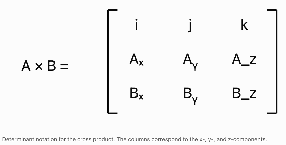
Expanding along the first row gives:
A × B = i(AᵧB_z − A_zBᵧ) − j(AₓB_z − A_zBₓ) + k(AₓBᵧ − AᵧBₓ)
The negative sign in the middle term is important.
Worked Example: Determinant Method
Given:
A = (1, 2, 3)
B = (4, 5, 6)
Calculate A × B.
Step 1: Calculate the i-component
i[(2)(6) − (3)(5)]
= i(12 − 15)
= −3i
Step 2: Calculate the j-component
−j[(1)(6) − (3)(4)]
= −j(6 − 12)
= +6j
Step 3: Calculate the k-component
k[(1)(5) − (2)(4)]
= k(5 − 8)
= −3k
Final Answer
A × B = −3i + 6j − 3k
In component form:
A × B = (−3, 6, −3)
Important Observation
The determinant method and component formula produce exactly the same result.
The determinant method can be especially useful when working with several three-dimensional vector calculations.
The Geometric Meaning of the Cross Product
The magnitude of the cross product is related to the magnitudes of the original vectors and the angle between them.
The formula is:
|A × B| = |A||B| sin θ
where:
-
|A × B| is the magnitude of the cross product.
-
|A| is the magnitude of vector A.
-
|B| is the magnitude of vector B.
-
θ is the angle between the vectors.
The angle θ is taken between 0° and 180°.
What Does the Formula Tell Us?
The magnitude depends on three factors:
-
The length of vector A.
-
The length of vector B.
-
The sine of the angle between them.
When the vectors are perpendicular, the magnitude of the cross product is greatest for fixed vector magnitudes.
When the vectors are parallel, the magnitude is zero.
How the Angle Affects the Cross Product
|
Angle θ |
sin θ |
Cross product magnitude |
|---|---|---|
|
0° |
0 |
Zero |
|
30° |
0.5 |
Half of |A||B| |
|
60° |
≈ 0.866 |
About 86.6% of |A||B| |
|
90° |
1 |
Maximum |
|
120° |
≈ 0.866 |
About 86.6% of |A||B| |
|
150° |
0.5 |
Half of |A||B| |
|
180° |
0 |
Zero |
Parallel Vectors
When θ = 0° or 180°:
sin θ = 0
Therefore:
|A × B| = 0
The cross product is the zero vector.
Perpendicular Vectors
When θ = 90°:
sin θ = 1
Therefore:
|A × B| = |A||B|
The magnitude is as large as possible for the given vector lengths.
Calculating Cross Product Magnitude
Worked Example: Perpendicular Vectors
Two perpendicular vectors have magnitudes:
|A| = 5
|B| = 8
Calculate the magnitude of their cross product.
Step 1: Write the formula
|A × B| = |A||B| sin θ
Step 2: Substitute
|A × B| = (5)(8) sin 90°
Step 3: Evaluate
sin 90° = 1
|A × B| = 40(1)
|A × B| = 40
Worked Example: Vectors at 30°
Two vectors have magnitudes:
|A| = 10
|B| = 6
The angle between them is 30°.
Calculate the magnitude of the cross product.
|A × B| = (10)(6) sin 30°
|A × B| = 60(0.5)
|A × B| = 30
Important Observation
The magnitude of the cross product is always non-negative.
The direction of the resulting vector is represented by its components, not by a negative magnitude.
The Right-Hand Rule
The direction of the cross product is determined by the right-hand rule.
The right-hand rule establishes which of the two possible perpendicular directions is correct.


Applying the Right-Hand Rule
-
Point the fingers of your right hand in the direction of vector A.
-
Curl your fingers toward vector B through the smaller angle between them.
-
Your thumb points in the direction of A × B.
The resulting vector is perpendicular to the plane containing A and B.
Important Principle
The order of the vectors matters.
A × B and B × A point in opposite directions.
Mathematically:
A × B = −(B × A)
This is called the anti-commutative property.
Worked Example: Right-Hand Rule with Unit Vectors
Consider the standard coordinate directions:
i = (1, 0, 0)
j = (0, 1, 0)
k = (0, 0, 1)
The cross products are:
i × j = k
j × k = i
k × i = j
Reversing the order changes the sign:
j × i = −k
k × j = −i
i × k = −j
Example
A = (1, 0, 0)
B = (0, 1, 0)
Calculate A × B.
Using the component formula:
A × B = (0, 0, 1)
Therefore:
A × B = k
The vector points in the positive z-direction.
Reversing the order:
B × A = (0, 0, −1)
Therefore:
B × A = −k
The direction is reversed.
Why the Right-Hand Rule Matters
The right-hand rule is used in:
-
Three-dimensional geometry.
-
Rotational mechanics.
-
Torque calculations.
-
Angular momentum.
-
Magnetic forces.
-
Surface orientation.
-
Computer graphics.
Finding a Vector Perpendicular to Two Vectors
One of the most important uses of the cross product is finding a vector perpendicular to two given vectors.
Worked Example
Given:
A = (2, 1, 0)
B = (1, 3, 2)
Find a vector perpendicular to both A and B.
Step 1: Calculate A × B
A × B = (AᵧB_z − A_zBᵧ, A_zBₓ − AₓB_z, AₓBᵧ − AᵧBₓ)
Step 2: Calculate the x-component
Cₓ = (1)(2) − (0)(3)
Cₓ = 2
Step 3: Calculate the y-component
Cᵧ = (0)(1) − (2)(2)
Cᵧ = −4
Step 4: Calculate the z-component
C_z = (2)(3) − (1)(1)
C_z = 6 − 1
C_z = 5
Final Answer
A × B = (2, −4, 5)
Verification
Check with A:
(2, −4, 5) · (2, 1, 0)
= 4 − 4 + 0
= 0
Check with B:
(2, −4, 5) · (1, 3, 2)
= 2 − 12 + 10
= 0
The resulting vector is perpendicular to both A and B.
Finding a Vector Perpendicular to a Plane
A plane is a flat two-dimensional surface extending through three-dimensional space.
A vector perpendicular to a plane is called a normal vector.
If two nonparallel vectors lie within a plane, their cross product produces a normal vector to that plane.
Geometric Interpretation
Suppose vectors A and B lie in the same plane.
Then:
N = A × B
is perpendicular to the plane.
The opposite vector:
−N = B × A
is also perpendicular to the plane.

Worked Example: Normal Vector to a Plane
A plane contains two direction vectors:
A = (1, 2, 0)
B = (3, 1, 4)
Find a normal vector.
Step 1: Calculate the cross product
N = A × B
Step 2: Calculate the x-component
Nₓ = (2)(4) − (0)(1)
Nₓ = 8
Step 3: Calculate the y-component
Nᵧ = (0)(3) − (1)(4)
Nᵧ = −4
Step 4: Calculate the z-component
N_z = (1)(1) − (2)(3)
N_z = 1 − 6
N_z = −5
Final Answer
N = (8, −4, −5)
This vector is perpendicular to the plane.
Any nonzero scalar multiple of N is also a normal vector.
For example:
(−8, 4, 5)
is another valid normal vector.
Finding the Equation of a Plane
The cross product can help determine the equation of a plane passing through three points.
A plane equation can be written:
ax + by + cz = d
The vector:
N = (a, b, c)
is perpendicular to the plane.
Worked Example: Plane Through Three Points
Find the equation of the plane passing through:
P = (1, 0, 0)
Q = (0, 1, 0)
R = (0, 0, 1)
Step 1: Find Two Direction Vectors
PQ = Q − P
PQ = (−1, 1, 0)
PR = R − P
PR = (−1, 0, 1)
Step 2: Calculate the Cross Product
N = PQ × PR
Nₓ = (1)(1) − (0)(0) = 1
Nᵧ = (0)(−1) − (−1)(1) = 1
N_z = (−1)(0) − (1)(−1) = 1
Therefore:
N = (1, 1, 1)
Step 3: Write the Plane Equation
Using the normal vector:
x + y + z = d
Step 4: Substitute a Known Point
Using P = (1, 0, 0):
1 + 0 + 0 = d
d = 1
Final Answer
x + y + z = 1
Verification
For Q = (0, 1, 0):
0 + 1 + 0 = 1
For R = (0, 0, 1):
0 + 0 + 1 = 1
All three points satisfy the equation.
Calculating Areas Using the Cross Product
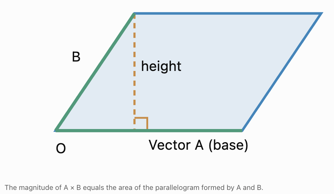
The magnitude of the cross product gives the area of a parallelogram formed by two vectors.
Area of parallelogram = |A × B|
This follows from the geometric formula:
|A × B| = |A||B| sin θ
For a parallelogram:
Area = base × perpendicular height
If |A| is the base, the perpendicular height is:
|B| sin θ
Therefore:
Area = |A||B| sin θ
Hence:
Area = |A × B|
Worked Example: Area of a Parallelogram
Given:
A = (3, 0, 0)
B = (0, 4, 0)
Find the area of the parallelogram formed by the vectors.
Step 1: Calculate the cross product
A × B = (0, 0, 12)
Step 2: Find the magnitude
|A × B| = √(0² + 0² + 12²)
|A × B| = √144
|A × B| = 12
Final Answer
Area = 12 square units
Verification
The vectors are perpendicular.
Therefore:
Area = base × height
Area = 3 × 4
Area = 12 square units
Both methods agree.
Worked Example: Area with Non-Perpendicular Vectors
Given:
A = (2, 1, 0)
B = (1, 3, 0)
Calculate the area of the parallelogram.
Step 1: Calculate the cross product
A × B = (0, 0, 5)
Step 2: Calculate the magnitude
|A × B| = √(0² + 0² + 5²)
|A × B| = 5
Final Answer
Area = 5 square units
Calculating the Area of a Triangle
A triangle formed by two vectors has half the area of the corresponding parallelogram.
Therefore:
Area of triangle = ½|A × B|
This formula is especially useful when the vertices of a triangle are given as coordinates in three-dimensional space.
Worked Example
Given:
A = (4, 0, 0)
B = (0, 3, 0)
Find the area of the triangle formed by these vectors and the origin.
Step 1: Calculate the cross product
A × B = (0, 0, 12)
Step 2: Find the magnitude
|A × B| = 12
Step 3: Calculate the triangle area
Area = ½(12)
Final Answer
Area = 6 square units
Verification
The triangle is right-angled.
Area = ½ × base × height
Area = ½ × 4 × 3
Area = 6 square units
Worked Example: Triangle in Three Dimensions
A triangle has vertices:
P = (1, 2, 3)
Q = (4, 2, 3)
R = (1, 6, 5)
Find its area.
Step 1: Construct Two Side Vectors
PQ = Q − P
PQ = (3, 0, 0)
PR = R − P
PR = (0, 4, 2)
Step 2: Calculate the Cross Product
PQ × PR = (0, −6, 12)
Step 3: Find the Magnitude
|PQ × PR| = √(0² + (−6)² + 12²)
= √(36 + 144)
= √180
= 6√5
Step 4: Calculate the Triangle Area
Area = ½(6√5)
Final Answer
Area = 3√5 square units
Approximately:
Area ≈ 6.71 square units
Important Observation
The cross product allows us to calculate the area of a triangle even when it does not lie in the xy-plane.
Finding the Angle Between Vectors Using the Cross Product
The magnitude formula can be rearranged:
|A × B| = |A||B| sin θ
Therefore:
sin θ = |A × B|/(|A||B|)
This can help determine the angle between vectors.
However, sine has the same value for an angle θ and its supplement 180° − θ.
Therefore, the cross product magnitude alone cannot always distinguish an acute angle from an obtuse angle.
The dot product can be used to resolve this ambiguity.
Worked Example
Given:
A = (1, 0, 0)
B = (1, 1, 0)
Find the angle between the vectors.
Step 1: Calculate the Cross Product
A × B = (0, 0, 1)
Therefore:
|A × B| = 1
Step 2: Calculate the Magnitudes
|A| = 1
|B| = √2
Step 3: Substitute
sin θ = 1/√2
sin θ ≈ 0.7071
Therefore, the angle is either:
45° or 135°
Step 4: Use the Dot Product
A · B = (1)(1) + (0)(1) + (0)(0)
A · B = 1
Since the dot product is positive, the angle is acute.
Final Answer
θ = 45°
Important Connection
The dot product and cross product provide complementary information:
-
The dot product helps determine the cosine of the angle.
-
The cross product magnitude helps determine the sine of the angle.
Together, they can determine the angle unambiguously for nonzero vectors.
Properties of the Cross Product
The cross product has several important algebraic properties.
Anti-Commutative Property
A × B = −(B × A)
Reversing the order reverses the direction.
Distributive Property
A × (B + C) = A × B + A × C
The cross product distributes over vector addition.
Scalar Multiplication
(kA) × B = k(A × B)
and:
A × (kB) = k(A × B)
where k is a scalar.
Cross Product of a Vector with Itself
A × A = (0, 0, 0)
The angle between a nonzero vector and itself is zero.
Since:
sin 0° = 0
the cross product has zero magnitude.
Cross Product of Parallel Vectors
If A and B are parallel:
A × B = (0, 0, 0)
Cross Product of Perpendicular Vectors
If A and B are perpendicular:
|A × B| = |A||B|
Important Limitation
The cross product is not generally associative.
In general:
A × (B × C) ≠ (A × B) × C
Parentheses matter when several cross products are involved.
Determining Whether Vectors Are Parallel
The cross product provides a useful test for parallel vectors.
Two nonzero vectors are parallel if and only if:
A × B = (0, 0, 0)
Worked Example
Given:
A = (2, 4, 6)
B = (1, 2, 3)
Determine whether the vectors are parallel.
Step 1: Calculate the Cross Product
A × B = (4(3) − 6(2), 6(1) − 2(3), 2(2) − 4(1))
A × B = (12 − 12, 6 − 6, 4 − 4)
A × B = (0, 0, 0)
Conclusion
The vectors are parallel.
Alternative Verification
B = ½A
Therefore, B is a scalar multiple of A.
This confirms that the vectors are parallel.
Real-World Application: Torque
Torque describes the turning effect of a force about a point or axis.
In three-dimensional physics, torque is calculated using the cross product:
τ = r × F
where:
-
τ is the torque vector.
-
r is the position vector from the pivot to the point where the force acts.
-
F is the applied force.
The magnitude is:
|τ| = |r||F| sin θ
where θ is the angle between r and F.
Worked Example: Turning a Wrench
A force of 40 N acts perpendicular to a wrench at a distance of 0.25 m from the pivot.
Calculate the torque magnitude.

Step 1: Identify the Values
|r| = 0.25 m
|F| = 40 N
θ = 90°
Step 2: Apply the Formula
|τ| = |r||F| sin θ
Step 3: Substitute
|τ| = (0.25)(40) sin 90°
Step 4: Calculate
|τ| = 10(1)
Final Answer
Torque magnitude = 10 N·m
Interpretation
The force produces a turning effect of 10 N·m about the pivot.
The torque vector points along the axis of rotation according to the right-hand rule.
Important Observation
A force applied directly toward the pivot produces no torque about that pivot because the angle between r and F is 0° or 180°.
Real-World Application: Surface Orientation in Computer Graphics
Three-dimensional computer graphics often represent objects using triangular surfaces.
To determine which direction a triangular surface faces, software can calculate a normal vector using the cross product.
Suppose a triangle has vertices:
P, Q, and R.
Construct:
PQ = Q − P
PR = R − P
Then:
N = PQ × PR
The vector N is perpendicular to the triangular surface.
Why Surface Normals Matter
Surface normals are used to:
-
Calculate lighting and shading.
-
Determine surface orientation.
-
Identify front-facing and back-facing polygons.
-
Model reflections.
-
Perform collision calculations.
-
Support three-dimensional rendering.

Important Observation
The order of the vertices matters.
If the vectors are reversed:
PR × PQ = −N
The normal vector points in the opposite direction.
This is important when deciding which side of a surface is considered the front.
Real-World Application: Angular Momentum
Angular momentum describes rotational motion.
For a particle, angular momentum about a chosen origin is:
L = r × p
where:
-
L is angular momentum.
-
r is the position vector.
-
p is linear momentum.
The magnitude is:
|L| = |r||p| sin θ
The direction follows the right-hand rule.
Example
A particle has:
r = (2, 0, 0) m
p = (0, 3, 0) kg·m/s
Calculate its angular momentum.
L = r × p
L = (0, 0, 6)
Final Answer
L = (0, 0, 6) kg·m²/s
The angular momentum vector points in the positive z-direction.
Real-World Application: Magnetic Force
The magnetic force on a moving charged particle can be calculated using a cross product:
F = q(v × B)
where:
-
F is the magnetic force.
-
q is the electric charge.
-
v is the velocity vector.
-
B is the magnetic field vector.
The magnetic force is perpendicular to both velocity and magnetic field when nonzero.
Important Observation
For a positive charge, the force direction follows the right-hand rule for v × B.
For a negative charge, the force points in the opposite direction.
The cross product therefore provides both the magnitude and direction needed to describe magnetic forces.
Solving Multi-Step Three-Dimensional Vector Problems
More advanced problems often combine cross products, dot products, vector magnitudes, and geometric reasoning.
Worked Example: Normal Vector and Triangle Area
Three points are given:
P = (0, 0, 0)
Q = (2, 1, 0)
R = (1, 3, 2)
Find:
-
A normal vector to the plane containing the points.
-
The area of triangle PQR.
Step 1: Construct Two Direction Vectors
PQ = (2, 1, 0)
PR = (1, 3, 2)
Step 2: Calculate the Cross Product
N = PQ × PR
Nₓ = (1)(2) − (0)(3) = 2
Nᵧ = (0)(1) − (2)(2) = −4
N_z = (2)(3) − (1)(1) = 5
Therefore:
N = (2, −4, 5)
Step 3: Calculate the Magnitude
|N| = √(2² + (−4)² + 5²)
|N| = √(4 + 16 + 25)
|N| = √45
|N| = 3√5
Step 4: Calculate the Triangle Area
Area = ½|N|
Area = 3√5/2
Final Answers
Normal vector = (2, −4, 5)
Triangle area = 3√5/2 square units
Approximately:
Area ≈ 3.35 square units
Verification
The normal vector must be perpendicular to both direction vectors.
N · PQ = (2)(2) + (−4)(1) + (5)(0)
= 4 − 4
= 0
N · PR = (2)(1) + (−4)(3) + (5)(2)
= 2 − 12 + 10
= 0
Both conditions are satisfied.
Choosing the Correct Cross Product Method
|
Problem |
Appropriate method |
|---|---|
|
Calculate a cross product |
Component formula or determinant |
|
Find a perpendicular vector |
A × B |
|
Find a plane normal |
Cross product of two nonparallel plane directions |
|
Calculate parallelogram area |
|A × B| |
|
Calculate triangle area |
½|A × B| |
|
Test whether nonzero vectors are parallel |
Check whether A × B = 0 |
|
Find cross product magnitude |
|A||B| sin θ |
|
Determine cross product direction |
Right-hand rule |
|
Calculate torque |
τ = r × F |
|
Calculate angular momentum |
L = r × p |
|
Calculate magnetic force |
F = q(v × B) |
General Problem-Solving Strategy
-
Identify the given vectors.
-
Determine whether they are expressed using components, magnitudes, or angles.
-
Identify what the problem asks for: a vector, magnitude, area, or orientation.
-
Select the appropriate cross product formula.
-
Calculate the components carefully.
-
Check the signs, especially the middle component.
-
Calculate the magnitude if required.
-
Apply the right-hand rule when direction matters.
-
Verify perpendicularity using dot products when appropriate.
-
Interpret the result in the original geometric or physical context.
Common Mistakes
Confusing the cross product with the dot product
The cross product produces a vector, while the dot product produces a scalar.
Using cosine instead of sine
The cross product magnitude uses sine.
Reversing the order of vectors
A × B and B × A point in opposite directions.
Forgetting the negative sign in determinant expansion
The middle term has a negative sign when expanding along the first row.
Making sign errors with negative components
Carefully evaluate each multiplication and subtraction.
Assuming the cross product lies in the same plane as the original vectors
The cross product is perpendicular to the plane containing the original vectors.
Confusing cross product magnitude with the cross product vector
The magnitude is a non-negative scalar, while the cross product has direction.
Assuming parallel vectors have a large cross product
Parallel vectors have a zero cross product.
Assuming perpendicular vectors have a zero cross product
Perpendicular nonzero vectors have the maximum possible cross product magnitude for their fixed lengths.
Forgetting to divide by two when calculating triangle area
The cross product magnitude gives parallelogram area, not triangle area.
Using the wrong side vectors for a triangle
Both side vectors should begin at the same vertex.
Assuming a zero cross product always means two distinct directions are parallel
A zero vector also produces a zero cross product with every vector.
Using the right-hand rule incorrectly
The order from the first vector to the second vector determines the direction.
Confusing surface normals with vectors lying in the plane
A normal vector is perpendicular to the plane.
Using sine alone to determine an angle without considering ambiguity
Sine cannot distinguish an angle from its supplement.
Failing to verify the result
A cross product should have zero dot product with both original vectors.
Key Terms
-
Vector: A quantity with magnitude and direction.
-
Scalar: A quantity described by magnitude alone.
-
Cross Product: An operation combining two three-dimensional vectors to produce a perpendicular vector.
-
Vector Product: Another name for the cross product.
-
Dot Product: An operation combining two vectors to produce a scalar.
-
Magnitude: The length or size of a vector.
-
Direction: The orientation in which a vector points.
-
Vector Component: The amount of a vector acting along a coordinate axis.
-
Three-Dimensional Vector: A vector with x-, y-, and z-components.
-
Unit Vector: A vector with magnitude 1.
-
Standard Basis Vectors: The unit vectors i, j, and k along the coordinate axes.
-
Right-Hand Rule: A method for determining the direction of a cross product.
-
Perpendicular Vectors: Nonzero vectors meeting at a 90° angle.
-
Orthogonal Vectors: Vectors whose dot product equals zero.
-
Parallel Vectors: Nonzero vectors that are scalar multiples of one another.
-
Zero Vector: A vector with all components equal to zero.
-
Normal Vector: A vector perpendicular to a surface or plane.
-
Plane: A flat two-dimensional surface extending through three-dimensional space.
-
Surface Orientation: The direction a surface faces in three-dimensional space.
-
Determinant: A scalar calculated from a square matrix, used in cross product calculations.
-
Anti-Commutative Property: The property that reversing the order of a cross product reverses its sign.
-
Distributive Property: A property allowing the cross product to be distributed across vector addition.
-
Parallelogram: A quadrilateral with two pairs of parallel opposite sides.
-
Area Vector: A vector perpendicular to a surface whose magnitude represents its area.
-
Triangle Area: Half the area of the parallelogram formed by two side vectors.
-
Sine: A trigonometric function used in calculating cross product magnitude.
-
Torque: The turning effect of a force about a point or axis.
-
Angular Momentum: A vector quantity describing rotational motion about a chosen origin.
-
Position Vector: A vector describing an object's location relative to an origin.
-
Linear Momentum: The product of mass and velocity.
-
Magnetic Force: A force experienced by a moving charge in a magnetic field.
-
Plane Equation: An algebraic equation describing a plane in three-dimensional space.
-
Vector Verification: Checking a calculated vector using known geometric or algebraic relationships.
Key Takeaways
-
The cross product combines two three-dimensional vectors to produce another vector.
-
The resulting vector is perpendicular to both original vectors.
-
The cross product can be calculated using vector components or a determinant.
-
The component formula is A × B = (AᵧB_z − A_zBᵧ, A_zBₓ − AₓB_z, AₓBᵧ − AᵧBₓ).
-
The magnitude of the cross product is |A × B| = |A||B| sin θ.
-
The right-hand rule determines the direction of the resulting vector.
-
Reversing the order of the vectors reverses the cross product direction.
-
The cross product is anti-commutative.
-
The cross product of parallel vectors is the zero vector.
-
Perpendicular nonzero vectors produce the greatest possible cross product magnitude for fixed magnitudes.
-
A cross product can be verified by taking its dot product with each original vector.
-
The cross product of two nonparallel vectors in a plane produces a normal vector.
-
Normal vectors can be used to determine equations of planes.
-
The magnitude of the cross product equals the area of the parallelogram formed by the original vectors.
-
Half the magnitude of the cross product gives the area of a triangle formed by the vectors.
-
The cross product can be used to calculate areas of triangles in three-dimensional space.
-
The dot product and cross product provide complementary information about vector angles.
-
The cross product is used to calculate torque and angular momentum.
-
Cross products are important in magnetic force calculations.
-
In computer graphics, cross products are used to calculate surface normals and orientations.
-
The central skill is using the cross product to calculate perpendicular vectors, determine orientation, calculate areas, and solve three-dimensional geometric and physical problems.
Check Your Understanding
Recall and Understanding
-
Define the cross product and explain how its result differs from the dot product.
-
State the component formula for the cross product of two three-dimensional vectors.
-
Explain the right-hand rule and why the order of vectors matters.
-
Describe the relationship between the magnitude of the cross product and the area of a parallelogram.
-
Explain why the cross product of two parallel vectors is the zero vector.
Application
-
Calculate A × B for A = (2, 3, 1) and B = (4, 1, 2).
-
Calculate A × B for A = (1, −2, 3) and B = (2, 4, −1).
-
Determine whether A = (2, 4, 6) and B = (1, 2, 3) are parallel using the cross product.
-
Find a vector perpendicular to both A = (1, 2, 0) and B = (3, 0, 1).
-
Two vectors have magnitudes 6 and 9 and form an angle of 30°. Calculate the magnitude of their cross product.
Analysis and Challenge
-
Find the area of the parallelogram formed by A = (3, 1, 0) and B = (1, 4, 0).
-
Find the area of the triangle with vertices P = (0, 0, 0), Q = (4, 0, 0), and R = (0, 3, 2).
-
Find a normal vector to the plane containing direction vectors A = (2, 1, 3) and B = (1, 4, 2).
-
A force of 60 N acts perpendicular to a wrench at a distance of 0.35 m from the pivot. Calculate the torque magnitude.
-
A plane passes through P = (1, 0, 0), Q = (0, 2, 0), and R = (0, 0, 3). Use the cross product to determine a normal vector and derive an equation of the plane.
Final Summary
The cross product is a fundamental operation in three-dimensional vector mathematics.
Unlike the dot product, which produces a scalar, the cross product produces a vector perpendicular to the two original vectors.
Its magnitude depends on the lengths of the original vectors and the sine of the angle between them, while its direction is determined by the right-hand rule.
The cross product can be calculated using vector components or determinant notation.
It provides a powerful method for finding normal vectors to planes, calculating the areas of parallelograms and triangles, and determining the orientation of surfaces.
It also has important applications in physics, engineering, computer graphics, and rotational mechanics.
The central principle is that the cross product connects vector magnitude, direction, and three-dimensional geometry, allowing us to determine perpendicular directions, calculate areas, and analyse orientation and rotation.
3. Lines and Planes
Learning outcomes
- I can write vector equations of lines.
- I can determine equations of planes.
- I can calculate intersections of lines and planes.
- I can identify parallel and perpendicular relationships.
- I can solve geometric problems in three dimensions.
Lines and Planes
Introduction to Lines and Planes in Three Dimensions
Geometry in three dimensions allows us to describe the positions and relationships of points, lines, and planes in space.
In two-dimensional geometry, lines are often represented using equations such as y = mx + b. In three dimensions, however, lines can extend in any direction, and planes can be tilted or oriented in many different ways.
Vectors provide a powerful method for describing these geometric objects.
Using vector equations, we can determine the position and direction of a line, describe the orientation of a plane, calculate intersections, and investigate whether geometric objects are parallel or perpendicular.
These techniques are important in:
-
Architecture and structural engineering.
-
Computer graphics and three-dimensional modelling.
-
Navigation and robotics.
-
Physics and mechanics.
-
Surveying and geographic information systems.
-
Aircraft and spacecraft navigation.
The study of lines and planes connects vector algebra, coordinate geometry, and geometric reasoning.
Understanding Three-Dimensional Coordinates
A point in three-dimensional space is represented using three coordinates:
P = (x, y, z)
Each coordinate describes the point's position along one of three mutually perpendicular axes.
-
The x-coordinate describes displacement along the x-axis.
-
The y-coordinate describes displacement along the y-axis.
-
The z-coordinate describes displacement along the z-axis.
The origin is:
O = (0, 0, 0)


Position Vectors
A position vector describes the location of a point relative to the origin.
For a point:
P = (3, 2, 5)
the position vector is:
OP = (3, 2, 5)
This vector describes a displacement of:
-
3 units along the x-axis.
-
2 units along the y-axis.
-
5 units along the z-axis.
Finding a Vector Between Two Points
Given two points:
A = (x₁, y₁, z₁)
B = (x₂, y₂, z₂)
the vector from A to B is:
AB = (x₂ − x₁, y₂ − y₁, z₂ − z₁)
Worked Example
Find the vector from:
A = (2, −1, 3)
to:
B = (5, 4, 7)
Step 1: Subtract corresponding coordinates
AB = (5 − 2, 4 − (−1), 7 − 3)
Step 2: Simplify
AB = (3, 5, 4)
This vector describes the direction and displacement from A to B.
Vector Equations of Lines
A line in three-dimensional space can be described using:
-
A known point on the line.
-
A direction vector parallel to the line.
The general vector equation is:
r = a + td
where:
-
r is the position vector of any point on the line.
-
a is the position vector of a known point on the line.
-
d is a nonzero direction vector.
-
t is a real-valued parameter.
The parameter t determines the position of a point along the line.
As t changes, the equation generates different points on the same line.

Understanding the Parameter
Consider:
r = (1, 2, 3) + t(2, 1, −1)
When t = 0:
r = (1, 2, 3)
When t = 1:
r = (3, 3, 2)
When t = 2:
r = (5, 4, 1)
When t = −1:
r = (−1, 1, 4)
All these points lie on the same line.
The parameter can be positive, negative, or zero.
Worked Example: Writing a Line Equation
Write the vector equation of a line passing through:
P = (2, 3, 1)
with direction vector:
d = (4, −2, 5)
Step 1: Identify the known point
a = (2, 3, 1)
Step 2: Identify the direction vector
d = (4, −2, 5)
Step 3: Substitute into the general equation
r = a + td
Final Answer
r = (2, 3, 1) + t(4, −2, 5)
This equation describes every point on the line.
Writing a Line Through Two Points
If two distinct points are given, the direction vector can be found by subtracting their coordinates.
Worked Example
Find the vector equation of the line through:
A = (1, 2, 3)
B = (4, 6, 5)
Step 1: Calculate the direction vector
AB = B − A
AB = (4 − 1, 6 − 2, 5 − 3)
AB = (3, 4, 2)
Step 2: Choose a known point
Use:
A = (1, 2, 3)
Step 3: Write the equation
r = (1, 2, 3) + t(3, 4, 2)
Verification
When t = 0:
r = (1, 2, 3)
This gives point A.
When t = 1:
r = (4, 6, 5)
This gives point B.
Both points satisfy the equation.
Parametric Equations of Lines
The vector equation of a line can be separated into three coordinate equations.
Given:
r = (x₀, y₀, z₀) + t(a, b, c)
the parametric equations are:
x = x₀ + at
y = y₀ + bt
z = z₀ + ct
Worked Example
Convert the vector equation:
r = (2, 1, −3) + t(4, −2, 5)
into parametric form.
Solution
The equations are:
x = 2 + 4t
y = 1 − 2t
z = −3 + 5t
Each equation describes how one coordinate changes as the parameter changes.
Finding a Point on the Line
Find the point corresponding to t = 3.
x = 2 + 4(3) = 14
y = 1 − 2(3) = −5
z = −3 + 5(3) = 12
Therefore:
P = (14, −5, 12)
Symmetric Equations of Lines
If all three components of the direction vector are nonzero, the parametric equations can be combined.
For:
x = x₀ + at
y = y₀ + bt
z = z₀ + ct
rearrange each equation:
t = (x − x₀)/a
t = (y − y₀)/b
t = (z − z₀)/c
Therefore:
(x − x₀)/a = (y − y₀)/b = (z − z₀)/c
Example
For:
r = (1, 2, 3) + t(2, 4, 5)
the symmetric equation is:
(x − 1)/2 = (y − 2)/4 = (z − 3)/5
Important Limitation
If a direction component is zero, the corresponding coordinate remains constant and should be written separately.
For example:
r = (1, 2, 3) + t(2, 0, 5)
gives:
(x − 1)/2 = (z − 3)/5
and:
y = 2
Division by zero must be avoided.
Determining Whether a Point Lies on a Line
A point lies on a line if its coordinates satisfy the line equation for one common parameter value.
Worked Example
Determine whether:
P = (7, 5, 9)
lies on:
r = (1, 2, 3) + t(2, 1, 2)
Step 1: Write the parametric equations
x = 1 + 2t
y = 2 + t
z = 3 + 2t
Step 2: Use the x-coordinate
7 = 1 + 2t
6 = 2t
t = 3
Step 3: Check the y-coordinate
5 = 2 + 3
5 = 5
Correct.
Step 4: Check the z-coordinate
9 = 3 + 2(3)
9 = 9
Correct.
Conclusion
P lies on the line.
Important Principle
The same parameter value must satisfy all three coordinate equations.
Understanding Planes
A plane is a flat two-dimensional surface extending infinitely in three-dimensional space.
A plane can be described using:
-
A point on the plane.
-
A nonzero vector perpendicular to the plane.
The perpendicular vector is called a normal vector.

Cartesian Equation of a Plane
The general Cartesian equation of a plane is:
ax + by + cz = d
where:
-
a, b, and c determine the orientation of the plane.
-
d determines its position relative to the origin.
-
(a, b, c) is a normal vector.
The normal vector is:
n = (a, b, c)
For example:
2x + 3y − z = 6
has normal vector:
n = (2, 3, −1)
Why the Normal Vector Matters
Every direction vector lying within the plane is perpendicular to the normal vector.
Therefore, if v is a direction vector in the plane:
n · v = 0
This relationship is fundamental to three-dimensional geometry.
Finding the Equation of a Plane from a Point and Normal Vector
If a plane passes through:
P = (x₀, y₀, z₀)
and has normal vector:
n = (a, b, c)
then its equation is:
a(x − x₀) + b(y − y₀) + c(z − z₀) = 0
This is called the point-normal form of a plane.
Worked Example
Find the equation of a plane passing through:
P = (1, 2, 3)
with normal vector:
n = (2, −1, 4)
Step 1: Write the point-normal equation
2(x − 1) − (y − 2) + 4(z − 3) = 0
Step 2: Expand
2x − 2 − y + 2 + 4z − 12 = 0
Step 3: Simplify
2x − y + 4z − 12 = 0
Final Answer
2x − y + 4z = 12
Verification
Substitute P = (1, 2, 3):
2(1) − 2 + 4(3)
= 2 − 2 + 12
= 12
The point satisfies the equation.
Vector Equations of Planes
A plane can also be represented using two nonparallel direction vectors.
The general vector equation is:
r = a + su + tv
where:
-
a is the position vector of a known point on the plane.
-
u and v are nonparallel direction vectors lying in the plane.
-
s and t are real-valued parameters.
Unlike a line, which requires one direction vector and one parameter, a plane requires two independent direction vectors and two parameters.
Worked Example
Write a vector equation of a plane passing through:
P = (1, 2, 0)
with direction vectors:
u = (2, 0, 1)
v = (0, 3, 1)
Solution
r = (1, 2, 0) + s(2, 0, 1) + t(0, 3, 1)
The corresponding parametric equations are:
x = 1 + 2s
y = 2 + 3t
z = s + t
Different combinations of s and t generate points throughout the plane.
Finding a Plane Through Three Points
Three non-collinear points determine a unique plane.
The cross product can be used to calculate a normal vector.
General Method
Given three points P, Q, and R:
-
Calculate PQ = Q − P.
-
Calculate PR = R − P.
-
Find the normal vector n = PQ × PR.
-
Use the point-normal equation.
Worked Example
Find the equation of the plane through:
P = (1, 0, 0)
Q = (0, 2, 0)
R = (0, 0, 3)
Step 1: Calculate two direction vectors
PQ = (−1, 2, 0)
PR = (−1, 0, 3)
Step 2: Calculate the cross product
n = PQ × PR
nₓ = (2)(3) − (0)(0) = 6
nᵧ = (0)(−1) − (−1)(3) = 3
n_z = (−1)(0) − (2)(−1) = 2
Therefore:
n = (6, 3, 2)
Step 3: Apply point-normal form
6(x − 1) + 3(y − 0) + 2(z − 0) = 0
Step 4: Simplify
6x − 6 + 3y + 2z = 0
Final Answer
6x + 3y + 2z = 6
Verification
For P:
6(1) + 3(0) + 2(0) = 6
For Q:
6(0) + 3(2) + 2(0) = 6
For R:
6(0) + 3(0) + 2(3) = 6
All three points lie on the plane.
Important Observation
If the three points are collinear, their direction vectors are parallel and their cross product is zero.
In that case, the three points do not determine a unique plane.
Parallel and Perpendicular Lines
Two lines can be parallel, intersecting, or skew.
In three-dimensional space, skew lines are lines that neither intersect nor are parallel.
Parallel Lines
Two lines are parallel when their direction vectors are scalar multiples of one another.
If:
d₁ = kd₂
for some nonzero scalar k, the directions are parallel.
Worked Example
Line 1:
r = (1, 2, 3) + t(2, 4, 6)
Line 2:
r = (3, 1, 0) + s(1, 2, 3)
Compare the direction vectors:
d₁ = (2, 4, 6)
d₂ = (1, 2, 3)
Since:
d₁ = 2d₂
the lines have parallel directions.
The lines are distinct because the point (3, 1, 0) does not lie on Line 1.
Conclusion
The lines are parallel.
Perpendicular Line Directions
Two direction vectors are perpendicular when their dot product is zero.
d₁ · d₂ = 0
However, in three dimensions, perpendicular direction vectors do not necessarily mean that two lines intersect.
The lines must intersect to be perpendicular as geometric lines.
Worked Example
Consider:
d₁ = (2, 1, 0)
d₂ = (1, −2, 3)
Calculate:
d₁ · d₂ = (2)(1) + (1)(−2) + (0)(3)
= 2 − 2
= 0
The direction vectors are perpendicular.
If lines with these directions intersect, the lines are perpendicular.
Skew Lines
Skew lines occur only in three-dimensional geometry.
They are neither parallel nor intersecting.

Worked Example
Consider:
Line 1:
r = (0, 0, 0) + t(1, 0, 0)
Line 2:
r = (0, 1, 1) + s(0, 1, 0)
The direction vectors are:
d₁ = (1, 0, 0)
d₂ = (0, 1, 0)
They are not parallel.
To test for intersection, equate the coordinates:
t = 0
0 = 1 + s
0 = 1
The final equation is impossible.
Therefore, the lines do not intersect.
Conclusion
The lines are skew.
Although their direction vectors are perpendicular, the lines themselves do not intersect.
Finding the Intersection of Two Lines
Two lines intersect when they share a common point.
Their vector equations can be equated to find the parameters corresponding to that point.
Worked Example
Find the intersection of:
Line 1:
r = (1, 2, 0) + t(1, 1, 2)
Line 2:
r = (3, 1, 4) + s(−1, 2, 0)
Step 1: Write the parametric equations
Line 1:
x = 1 + t
y = 2 + t
z = 2t
Line 2:
x = 3 − s
y = 1 + 2s
z = 4
Step 2: Equate the z-coordinates
2t = 4
t = 2
Step 3: Equate the x-coordinates
1 + 2 = 3 − s
3 = 3 − s
s = 0
Step 4: Check the y-coordinates
Line 1:
y = 2 + 2 = 4
Line 2:
y = 1 + 2(0) = 1
The y-coordinates do not agree.
Conclusion
The lines do not intersect.
Since their direction vectors are not parallel, they are skew.
Important Lesson
In three dimensions, solving two coordinate equations is not enough.
All three coordinates must agree.
Worked Example: Intersecting Lines
Consider:
Line 1:
r = (1, 0, 2) + t(2, 1, −1)
Line 2:
r = (3, 1, 1) + s(1, −1, 2)
Step 1: Equate coordinates
1 + 2t = 3 + s
t = 1 − s
2 − t = 1 + 2s
Step 2: Solve
From the second equation:
t = 1 − s
Substitute into the first:
1 + 2(1 − s) = 3 + s
3 − 2s = 3 + s
−3s = 0
s = 0
Therefore:
t = 1
Step 3: Check the z-coordinate
2 − 1 = 1 + 2(0)
1 = 1
Correct.
Step 4: Find the intersection
Using Line 1:
x = 1 + 2(1) = 3
y = 1
z = 2 − 1 = 1
Final Answer
Intersection point = (3, 1, 1)
Parallel and Perpendicular Planes
The relationship between two planes can be determined by comparing their normal vectors.
Parallel Planes
Two planes are parallel when their normal vectors are parallel.
For planes with normals n₁ and n₂:
n₁ = kn₂
for some nonzero scalar k.
Worked Example
Plane 1:
2x + 4y − 6z = 8
Plane 2:
x + 2y − 3z = 10
The normal vectors are:
n₁ = (2, 4, −6)
n₂ = (1, 2, −3)
Since:
n₁ = 2n₂
the planes have parallel orientations.
Dividing Plane 1 by 2 gives:
x + 2y − 3z = 4
Plane 2 is:
x + 2y − 3z = 10
They have different constants.
Conclusion
The planes are distinct and parallel.
Coincident Planes
If one entire plane equation is a nonzero scalar multiple of the other, both equations describe the same plane.
For example:
2x + 4y − 6z = 8
and:
x + 2y − 3z = 4
describe the same plane.
Perpendicular Planes
Two planes are perpendicular when their normal vectors are perpendicular.
Therefore:
n₁ · n₂ = 0
Worked Example
Plane 1:
2x + y − z = 4
Plane 2:
x − y + z = 2
The normal vectors are:
n₁ = (2, 1, −1)
n₂ = (1, −1, 1)
Calculate the dot product:
n₁ · n₂ = 2(1) + 1(−1) + (−1)(1)
= 2 − 1 − 1
= 0
Conclusion
The planes are perpendicular.
Relationships Between Lines and Planes
A line and a plane may:
-
Intersect at one point.
-
Be parallel without intersecting.
-
Have the entire line contained in the plane.
-
Be perpendicular.
These relationships can be determined using the line's direction vector and the plane's normal vector.
Let:
d = direction vector of the line
n = normal vector of the plane
Line Parallel to a Plane
A line has a direction parallel to a plane when:
d · n = 0
The line may lie entirely within the plane or may be separate from it.
Line Perpendicular to a Plane
A line is perpendicular to a plane when its direction vector is parallel to the plane's normal vector.
Therefore:
d = kn
for some nonzero scalar k.
Worked Example
Consider a line with direction vector:
d = (2, 4, −2)
and a plane with normal vector:
n = (1, 2, −1)
Since:
d = 2n
the line is perpendicular to the plane.
Worked Example: Parallel Direction
A line has direction vector:
d = (2, −1, 0)
A plane has normal vector:
n = (1, 2, 3)
Calculate:
d · n = (2)(1) + (−1)(2) + (0)(3)
= 2 − 2
= 0
The line's direction is parallel to the plane.
Additional information about the line's position is needed to determine whether it lies within the plane or is separate from it.
Finding the Intersection of a Line and a Plane
To find the intersection of a line and a plane:
-
Write the parametric equations of the line.
-
Substitute them into the plane equation.
-
Solve for the line parameter.
-
Substitute the parameter back into the line equation.
-
Verify the intersection point.

Worked Example
Find the intersection of:
Line:
r = (1, 2, 3) + t(2, −1, 1)
Plane:
x + 2y + z = 10
Step 1: Write the parametric equations
x = 1 + 2t
y = 2 − t
z = 3 + t
Step 2: Substitute into the plane equation
(1 + 2t) + 2(2 − t) + (3 + t) = 10
Step 3: Expand
1 + 2t + 4 − 2t + 3 + t = 10
Step 4: Simplify
8 + t = 10
t = 2
Step 5: Find the coordinates
x = 1 + 2(2) = 5
y = 2 − 2 = 0
z = 3 + 2 = 5
Final Answer
Intersection point = (5, 0, 5)
Verification
Substitute into the plane equation:
5 + 2(0) + 5 = 10
10 = 10
The point lies on the plane.
When a Line Does Not Intersect a Plane at One Point
Sometimes substituting the line equation into the plane produces no unique solution.
Parallel but Separate
Suppose:
Line:
r = (0, 0, 2) + t(1, 1, 0)
Plane:
z = 0
The line always has:
z = 2
The plane requires:
z = 0
Therefore, the line never intersects the plane.
Line Contained in a Plane
Consider:
Line:
r = (1, 2, 0) + t(1, −1, 0)
Plane:
z = 0
Every point on the line has:
z = 0
Therefore, every point on the line lies in the plane.
Important Principle
Substitution into the plane equation may produce:
-
One solution: a single intersection point.
-
No solution: the line is parallel and separate.
-
An identity true for every parameter value: the line lies entirely in the plane.
Finding the Intersection of Two Planes
Two distinct nonparallel planes intersect along a line.
The direction vector of their intersection line is perpendicular to both plane normals.
Therefore:
d = n₁ × n₂

Worked Example
Find the line of intersection of:
Plane 1:
x + y + z = 6
Plane 2:
x − y + z = 2
Step 1: Subtract the equations
(x + y + z) − (x − y + z) = 6 − 2
2y = 4
y = 2
Step 2: Substitute into Plane 1
x + 2 + z = 6
x + z = 4
Step 3: Introduce a parameter
Let:
z = t
Then:
x = 4 − t
Step 4: Write the parametric equations
x = 4 − t
y = 2
z = t
Final Answer
r = (4, 2, 0) + t(−1, 0, 1)
Verification Using Cross Products
The plane normals are:
n₁ = (1, 1, 1)
n₂ = (1, −1, 1)
Their cross product is:
n₁ × n₂ = (2, 0, −2)
This is a scalar multiple of:
(−1, 0, 1)
Therefore, the direction vector is correct.
Distance from a Point to a Plane
The perpendicular distance from a point to a plane can be calculated using the plane equation.
For a plane:
ax + by + cz + d = 0
and a point:
P = (x₀, y₀, z₀)
the distance is:
Distance = |ax₀ + by₀ + cz₀ + d| / √(a² + b² + c²)
The absolute value ensures that distance is non-negative.
Worked Example
Find the distance from:
P = (1, 2, 3)
to the plane:
2x − y + 2z − 5 = 0
Step 1: Identify the coefficients
a = 2
b = −1
c = 2
d = −5
Step 2: Substitute
Distance = |2(1) − 1(2) + 2(3) − 5| / √(2² + (−1)² + 2²)
Step 3: Simplify the numerator
|2 − 2 + 6 − 5| = |1| = 1
Step 4: Simplify the denominator
√(4 + 1 + 4) = √9 = 3
Final Answer
Distance = 1/3 unit
Distance Between Parallel Planes
For parallel planes written with the same normal coefficients:
ax + by + cz = d₁
ax + by + cz = d₂
the perpendicular distance between them is:
Distance = |d₂ − d₁| / √(a² + b² + c²)
Worked Example
Find the distance between:
2x + 2y + z = 4
and:
2x + 2y + z = 13
Step 1: Identify the constants
d₁ = 4
d₂ = 13
Step 2: Calculate the difference
|13 − 4| = 9
Step 3: Calculate the normal magnitude
√(2² + 2² + 1²)
= √9
= 3
Step 4: Calculate the distance
Distance = 9/3
Final Answer
Distance = 3 units
Angles Between Lines and Planes
Dot products can be used to determine angles involving lines and planes.
Angle Between Two Lines
For two nonzero direction vectors d₁ and d₂:
cos θ = (d₁ · d₂)/(|d₁||d₂|)
This calculates the angle between the chosen direction vectors.
For the smaller angle between the geometric lines, use:
cos θ = |d₁ · d₂|/(|d₁||d₂|)
where 0° ≤ θ ≤ 90°.
Angle Between Two Planes
The angle between two planes is determined by the angle between their normal vectors.
For the smaller angle:
cos θ = |n₁ · n₂|/(|n₁||n₂|)
Angle Between a Line and a Plane
The angle between a line and a plane is complementary to the smaller angle between the line's direction vector and the plane's normal.
Therefore:
sin θ = |d · n|/(|d||n|)
where θ is the acute angle between the line and plane, or 0° or 90° in the limiting cases.
Worked Example
A line has direction vector:
d = (1, 0, 1)
A plane has normal vector:
n = (0, 0, 1)
Find the angle between the line and plane.
Step 1: Calculate the dot product
d · n = 1
Step 2: Calculate the magnitudes
|d| = √2
|n| = 1
Step 3: Apply the formula
sin θ = 1/√2
Step 4: Calculate
θ = 45°
The line forms a 45° angle with the plane.
Real-World Application: Architecture and Engineering
Architects and engineers use three-dimensional geometry to model structural components, surfaces, and intersections.
Examples include:
-
Roof planes.
-
Support beams.
-
Walls and floors.
-
Structural joints.
-
Bridge components.
-
Inclined surfaces.


Worked Example: A Support Beam Intersecting a Roof
A beam follows the line:
r = (0, 0, 1) + t(2, 1, 3)
A roof surface is represented by:
z = 7
Determine where the beam meets the roof.
Step 1: Write the beam equations
x = 2t
y = t
z = 1 + 3t
Step 2: Use the roof equation
1 + 3t = 7
3t = 6
t = 2
Step 3: Find the coordinates
x = 2(2) = 4
y = 2
z = 7
Final Answer
The beam intersects the roof at (4, 2, 7).
This type of calculation helps determine the locations of structural connections.
Real-World Application: Computer Graphics
Computer graphics systems use lines and planes to represent:
-
Camera rays.
-
Walls and floors.
-
Object surfaces.
-
Lighting directions.
-
Collision boundaries.
-
Three-dimensional models.
A camera ray can be represented by a line equation:
r = a + td
An object's surface may be represented by a plane.
To determine where the ray strikes the surface, the line equation is substituted into the plane equation.
This process is called ray-plane intersection.

Important Observation
In ray tracing, a ray usually requires:
t ≥ 0
This ensures that the calculated intersection lies in front of the ray's starting point rather than behind it.
A mathematical line extends infinitely in both directions, but a ray extends in only one direction.
Real-World Application: Navigation and Robotics
Robots and autonomous systems use three-dimensional coordinates to determine positions and movement paths.
A movement path can be modelled using:
r = a + td
Surfaces and obstacles can be represented using plane equations.
These models allow systems to calculate:
-
Where a movement path intersects a surface.
-
Whether a path is parallel to an obstacle.
-
The distance from a position to a wall.
-
The orientation of a surface.
-
The angle between a movement direction and a surface.

Example
A robotic tool follows:
r = (1, 2, 3) + t(0, 0, −1)
A work surface is:
z = 0
Find the point where the tool's path meets the surface.
The z-coordinate is:
z = 3 − t
Set z = 0:
3 − t = 0
t = 3
Therefore:
Intersection = (1, 2, 0)
This represents the position where the tool reaches the work surface.
Real-World Application: Aircraft Navigation
Aircraft movement can be approximated using vector equations over short periods when velocity is nearly constant.
Suppose an aircraft begins at:
P = (10, 20, 5)
and follows a displacement direction:
d = (3, 4, 1)
Its path can be modelled by:
r = (10, 20, 5) + t(3, 4, 1)
A horizontal altitude surface can be represented by:
z = constant
An inclined surface can be represented by a more general plane equation.
These mathematical models can be used to study path intersections, distances, and orientations.
Real aircraft navigation requires more sophisticated models that account for changing velocity, atmospheric conditions, and other factors.
Solving Multi-Step Three-Dimensional Geometry Problems
More advanced problems combine line equations, plane equations, cross products, dot products, and intersection calculations.
Worked Example: Line Through Two Points and Plane Intersection
A line passes through:
A = (1, 2, 0)
B = (3, 5, 4)
A plane has equation:
x + y + z = 15
Find the intersection point.
Step 1: Find the line direction vector
AB = B − A
AB = (2, 3, 4)
Step 2: Write the line equation
r = (1, 2, 0) + t(2, 3, 4)
Step 3: Write the parametric equations
x = 1 + 2t
y = 2 + 3t
z = 4t
Step 4: Substitute into the plane
(1 + 2t) + (2 + 3t) + 4t = 15
Step 5: Simplify
3 + 9t = 15
9t = 12
t = 4/3
Step 6: Calculate the intersection coordinates
x = 1 + 2(4/3)
x = 11/3
y = 2 + 3(4/3)
y = 6
z = 4(4/3)
z = 16/3
Final Answer
Intersection = (11/3, 6, 16/3)
Verification
11/3 + 6 + 16/3
= 27/3 + 6
= 9 + 6
= 15
The point satisfies the plane equation.
Comparing Lines and Planes
|
Feature |
Line |
Plane |
|---|---|---|
|
Dimension |
One-dimensional |
Two-dimensional |
|
Defined by |
Point and direction |
Point and two nonparallel directions, or point and normal |
|
Vector equation |
r = a + td |
r = a + su + tv |
|
Parameters |
One |
Two |
|
Direction information |
Direction vector |
Two plane directions or a normal vector |
|
Common Cartesian form |
Parametric or symmetric equations |
ax + by + cz = d |
|
Possible intersections |
Points or coincident lines |
Lines or coincident planes |
Important Distinction
A line has one independent direction.
A plane has two independent directions.
A plane's normal vector is perpendicular to both directions lying within the plane.
A Systematic Method for Solving Lines and Planes Problems
Identify the Geometric Objects
Determine whether the problem involves points, lines, planes, or combinations of these objects.
Identify the Given Information
Look for:
-
Known points.
-
Direction vectors.
-
Normal vectors.
-
Cartesian equations.
-
Parametric equations.
Choose an Appropriate Representation
Use vector equations for lines and planes when direction information is important.
Use Cartesian plane equations when substituting coordinates or finding intersections.
Determine Direction Relationships
Use scalar multiples to test parallelism.
Use dot products to test perpendicularity.
Use cross products to calculate plane normals or intersection directions.
Solve Algebraically
Equate coordinate expressions or substitute parametric equations into Cartesian equations.
Check All Conditions
In three-dimensional geometry, all three coordinates must satisfy the relevant equations.
Interpret the Result
Explain whether the objects intersect, are parallel, are perpendicular, coincide, or are skew.
Verify
Substitute calculated points into the original equations whenever possible.
Common Mistakes
Confusing position vectors and direction vectors
A position vector identifies a point relative to the origin, while a direction vector describes the orientation of a line.
Using a zero direction vector
A valid line equation requires a nonzero direction vector.
Using parallel direction vectors to define a plane
A plane requires two nonparallel direction vectors.
Confusing a plane's normal vector with a direction vector in the plane
The normal vector is perpendicular to every direction in the plane.
Assuming all nonparallel lines intersect
In three dimensions, nonparallel lines may be skew.
Assuming perpendicular direction vectors guarantee intersecting lines
The lines must actually intersect to be perpendicular as geometric lines.
Failing to check all three coordinates
An apparent line intersection must satisfy x-, y-, and z-coordinate equations simultaneously.
Using different parameter values for coordinates of the same point on one line
One common parameter value must satisfy all coordinates of a point on a given line.
Confusing parallel and coincident planes
Parallel normals do not necessarily mean the planes are identical.
Assuming a line with direction parallel to a plane never intersects it
The line may lie entirely within the plane.
Confusing line-plane perpendicularity with line-plane parallelism
A line perpendicular to a plane has a direction parallel to the plane's normal.
A line with direction parallel to the plane has a direction perpendicular to the plane's normal.
Forgetting to use absolute values in distance formulas
Distance cannot be negative.
Using an incorrect cross product
A sign error in the cross product can produce an incorrect plane normal.
Ignoring special cases in symmetric equations
A zero direction component produces a constant coordinate, not a fraction with zero denominator.
Assuming every pair of planes intersects in a line
Parallel planes may be distinct or coincident.
Failing to verify calculated intersection points
Substitution into the original equations helps detect algebraic errors.
Key Terms
-
Three-Dimensional Space: A geometric system described using three independent coordinate directions.
-
Cartesian Coordinate System: A system that locates points using coordinates along perpendicular axes.
-
Origin: The point (0, 0, 0) where the coordinate axes meet.
-
Position Vector: A vector describing a point's location relative to the origin.
-
Direction Vector: A nonzero vector describing the direction of a line or movement.
-
Line: A one-dimensional geometric object extending infinitely in two directions.
-
Plane: A flat two-dimensional surface extending infinitely in three-dimensional space.
-
Vector Equation of a Line: An equation expressing points on a line using a known point and direction vector.
-
Parametric Equation: An equation describing coordinates in terms of one or more parameters.
-
Parameter: A variable used to generate points on a line or plane.
-
Symmetric Equation: A line equation obtained by eliminating the parameter from parametric equations.
-
Vector Equation of a Plane: An equation using a known point and two nonparallel direction vectors.
-
Cartesian Equation of a Plane: An equation of the form ax + by + cz = d.
-
Normal Vector: A vector perpendicular to a plane.
-
Point-Normal Form: A plane equation constructed from a known point and normal vector.
-
Dot Product: An operation producing a scalar from two vectors.
-
Cross Product: An operation producing a vector perpendicular to two given vectors.
-
Parallel Lines: Distinct lines with parallel direction vectors that do not intersect.
-
Perpendicular Lines: Lines that intersect at a right angle.
-
Skew Lines: Lines in three dimensions that are neither parallel nor intersecting.
-
Parallel Planes: Distinct planes with parallel normal vectors.
-
Perpendicular Planes: Planes whose normal vectors are perpendicular.
-
Coincident Planes: Different equations describing the same plane.
-
Intersection: A point or set of points shared by geometric objects.
-
Line-Plane Intersection: A point or line shared by a line and a plane.
-
Plane-Plane Intersection: A line shared by two distinct nonparallel planes.
-
Scalar Multiple: A vector obtained by multiplying another vector by a number.
-
Collinear Points: Points lying on the same straight line.
-
Non-Collinear Points: Points that do not all lie on one straight line.
-
Orthogonal Vectors: Vectors whose dot product is zero.
-
Perpendicular Distance: The shortest distance from a point to a line or plane.
-
Ray: A geometric object beginning at a point and extending indefinitely in one direction.
-
Ray-Plane Intersection: The point where a ray meets a plane, when such a point exists.
-
Geometric Model: A mathematical representation of a geometric or physical situation.
-
Verification: Checking that a result satisfies the original equations or geometric conditions.
Key Takeaways
-
A line in three-dimensional space can be represented using a known point and a nonzero direction vector.
-
The vector equation of a line is r = a + td.
-
The parameter t determines the position of a point on the line.
-
A line through two distinct points uses their coordinate difference as a direction vector.
-
Parametric equations describe each coordinate separately.
-
Symmetric equations can be used when the relevant direction components are nonzero.
-
A plane is a two-dimensional surface in three-dimensional space.
-
A plane can be described using a point and a normal vector.
-
The Cartesian equation of a plane is ax + by + cz = d.
-
The vector (a, b, c) is normal to the plane.
-
A plane can also be described using a point and two nonparallel direction vectors.
-
Three non-collinear points determine a unique plane.
-
The cross product can be used to find a normal vector to a plane.
-
Two lines have parallel directions when their direction vectors are scalar multiples.
-
Two intersecting lines are perpendicular when their direction vectors have a zero dot product.
-
Skew lines are nonparallel lines that do not intersect.
-
Two planes have parallel orientations when their normal vectors are parallel.
-
Two planes are perpendicular when their normal vectors have a zero dot product.
-
A line is perpendicular to a plane when its direction vector is parallel to the plane's normal vector.
-
A line has direction parallel to a plane when its direction vector is perpendicular to the plane's normal vector.
-
Line-plane intersections are found by substituting parametric equations into the plane equation.
-
Two distinct nonparallel planes intersect along a line.
-
The cross product of two plane normals gives a direction vector for their intersection line.
-
Distance formulas allow us to calculate perpendicular distances from points to planes and between parallel planes.
-
Dot products can be used to calculate angles between lines and planes.
-
Lines and planes are important mathematical models in engineering, architecture, navigation, robotics, and computer graphics.
-
The central skill is using vector equations, dot products, cross products, and algebraic methods to describe and analyse geometric relationships in three dimensions.
Check Your Understanding
Recall and Understanding
-
Explain what information is needed to write the vector equation of a line.
-
Describe the difference between a direction vector and a normal vector.
-
State the vector equation of a line and explain the meaning of each symbol.
-
Explain the difference between parallel, perpendicular, and skew lines.
-
Describe how the cross product can be used to determine the equation of a plane.
Application
-
Write the vector equation of a line passing through P = (2, 1, 3) with direction vector d = (4, −1, 2).
-
Find the vector equation of the line passing through A = (1, 2, 0) and B = (4, 6, 3).
-
Determine whether the point P = (7, 5, 9) lies on the line r = (1, 2, 3) + t(2, 1, 2).
-
Find the equation of a plane passing through P = (1, 2, 3) with normal vector n = (2, −1, 4).
-
Determine whether the planes 2x + 4y − 2z = 6 and x + 2y − z = 5 are parallel, perpendicular, or coincident.
Analysis and Challenge
-
Find the intersection of the line r = (1, 0, 2) + t(2, 1, −1) with the plane x + y + z = 8.
-
Determine whether the lines r = (0, 0, 0) + t(1, 2, 3) and r = (1, 1, 1) + s(2, 4, 6) are parallel, coincident, or intersecting.
-
Find the equation of the plane through P = (1, 0, 0), Q = (0, 2, 0), and R = (0, 0, 4).
-
Calculate the perpendicular distance from P = (2, 3, 1) to the plane 2x − y + 2z − 7 = 0.
-
Find the line of intersection of the planes x + y + z = 6 and x − y + z = 2. Express your answer as a vector equation.
Final Summary
Lines and planes form the foundation of three-dimensional coordinate geometry.
Vectors provide a systematic method for describing their positions, directions, and orientations.
A line is defined using a known point and a direction vector, while a plane can be defined using a point and a normal vector or two nonparallel direction vectors.
Dot products allow us to investigate perpendicular relationships and angles, while cross products allow us to calculate normal vectors and intersection directions.
Algebraic methods make it possible to find intersections between lines, between lines and planes, and between planes.
These techniques also allow us to calculate distances and solve practical geometric problems in three-dimensional space.
The central principle is that vector equations provide a powerful and consistent way to describe lines and planes, determine their relationships, and solve geometric problems involving position, direction, intersection, and distance in three dimensions.
4. Vector Transformations
Learning outcomes
- I can apply translations using vectors.
- I can describe geometric transformations with vectors.
- I can combine multiple transformations.
- I can analyse geometric movement.
- I can model transformations mathematically.
Vector Transformations
Introduction to Vector Transformations
Geometric transformations describe how points, lines, shapes, and objects move or change position in space.
A transformation may move an object without changing its shape, rotate it around a point, reflect it across a line, or change its size.
Vectors provide a mathematical way to describe these transformations precisely.
For example, instead of saying that a triangle moves four units to the right and three units upward, we can describe the movement using the translation vector:
v = (4, 3)
Vector transformations are useful in geometry, physics, engineering, computer graphics, animation, robotics, and navigation.
They allow us to:
-
Describe the movement of geometric figures.
-
Calculate the new coordinates of transformed points.
-
Combine multiple transformations.
-
Determine the overall effect of a sequence of movements.
-
Model geometric changes using vectors and matrices.
-
Analyse whether lengths, angles, and orientations are preserved.
The central idea is that transformations can be represented using mathematical rules that map original points to new positions.
Understanding Geometric Transformations
A geometric transformation is a rule that maps each point of a figure to another point.
The original figure is called the preimage.
The resulting figure is called the image.
For example, if point A is transformed into point A′, we write:
A → A′
The prime symbol (′) indicates the transformed point.
A transformation can be represented using coordinate rules.
For example:
(x, y) → (x + 3, y − 2)
This means every point moves:
-
3 units to the right.
-
2 units downward.
Common Types of Transformations
|
Transformation |
Description |
Effect |
|---|---|---|
|
Translation |
Slides a figure |
Changes position |
|
Reflection |
Flips a figure across a line |
Reverses orientation |
|
Rotation |
Turns a figure around a point |
Changes direction |
|
Dilation |
Enlarges or reduces a figure |
Changes size |
|
Combination |
Applies multiple transformations |
Depends on the operations |
Translations, reflections, and rotations are rigid transformations, also called isometries.
They preserve distances and angles.
Dilations generally change lengths but preserve angles and proportional relationships.


Translations Using Vectors
A translation moves every point of a figure by the same distance in the same direction.
The translation vector describes this movement.
For a two-dimensional translation:
v = (a, b)
the transformation rule is:
(x, y) → (x + a, y + b)
where:
-
a is the horizontal displacement.
-
b is the vertical displacement.
Interpreting Translation Vectors
|
Translation vector |
Movement |
|---|---|
|
(4, 0) |
4 units right |
|
(−3, 0) |
3 units left |
|
(0, 5) |
5 units up |
|
(0, −2) |
2 units down |
|
(3, 4) |
3 right, 4 up |
|
(−2, −5) |
2 left, 5 down |
A positive x-component moves a point right.
A negative x-component moves a point left.
A positive y-component moves a point up.
A negative y-component moves a point down.
Worked Example: Translating a Point
Point A has coordinates:
A = (2, 3)
Translate A using:
v = (4, −2)
Step 1: Write the translation rule
A′ = A + v
Step 2: Substitute
A′ = (2, 3) + (4, −2)
Step 3: Add corresponding components
A′ = (2 + 4, 3 − 2)
Final Answer
A′ = (6, 1)
The point moves four units right and two units down.
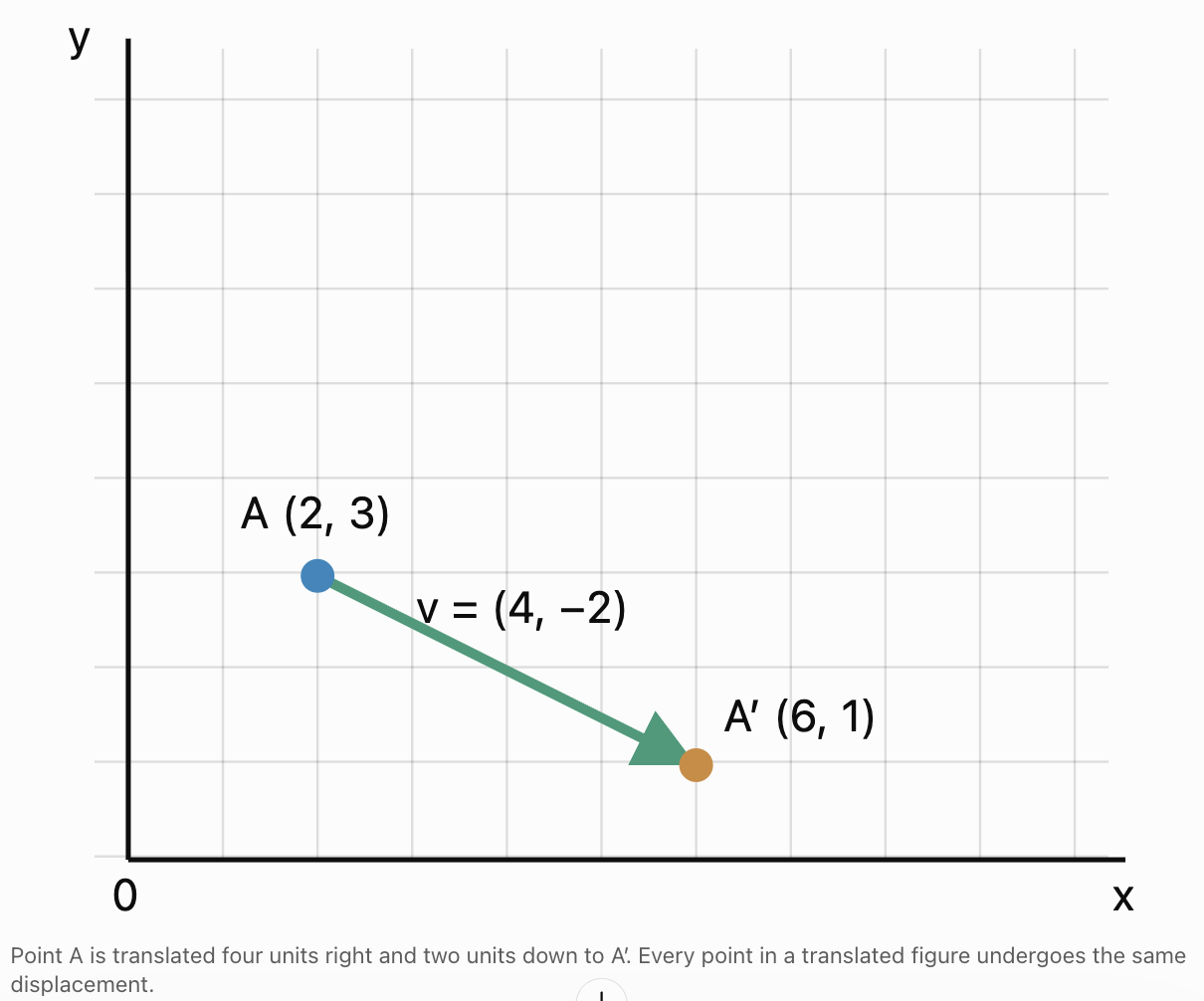
Translating Geometric Figures
When a figure is translated, every vertex moves according to the same translation vector.
Worked Example: Translating a Triangle
A triangle has vertices:
A = (1, 1)
B = (4, 1)
C = (2, 4)
Translate the triangle using:
v = (3, 2)
Step 1: Translate A
A′ = (1 + 3, 1 + 2)
A′ = (4, 3)
Step 2: Translate B
B′ = (4 + 3, 1 + 2)
B′ = (7, 3)
Step 3: Translate C
C′ = (2 + 3, 4 + 2)
C′ = (5, 6)
Final Answer
The transformed triangle has vertices:
A′ = (4, 3)
B′ = (7, 3)
C′ = (5, 6)
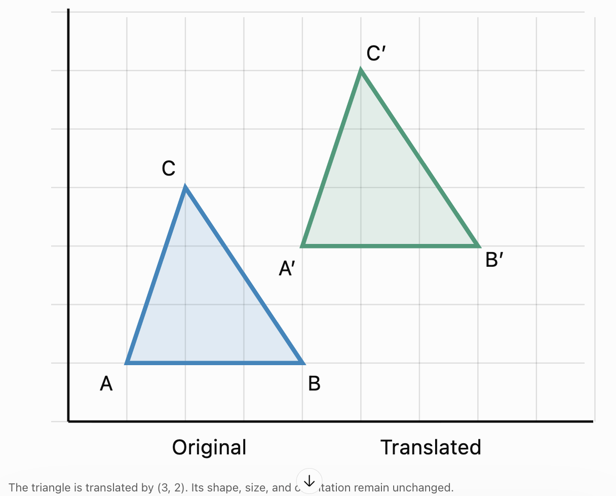
Important Observation
A translation preserves:
-
Side lengths.
-
Angle measurements.
-
Area.
-
Perimeter.
-
Parallel relationships.
-
Orientation.
The image and preimage are congruent.
Finding a Translation Vector
Sometimes the original and transformed points are given, and the translation vector must be determined.
If:
A = (x₁, y₁)
A′ = (x₂, y₂)
then:
v = A′ − A
Therefore:
v = (x₂ − x₁, y₂ − y₁)
Worked Example
Point P = (−2, 5) is translated to:
P′ = (4, 1)
Find the translation vector.
Step 1: Subtract the original coordinates
v = P′ − P
Step 2: Substitute
v = (4 − (−2), 1 − 5)
Step 3: Simplify
v = (6, −4)
Interpretation
The point moves:
-
6 units right.
-
4 units down.
Verification
(−2, 5) + (6, −4) = (4, 1)
The translation is correct.
Magnitude and Direction of a Translation
A translation vector describes both distance and direction.
For:
v = (a, b)
the magnitude is:
|v| = √(a² + b²)
This gives the straight-line distance through which each point moves.
Worked Example
A figure is translated by:
v = (6, 8)
Calculate the distance moved.
Step 1: Apply the magnitude formula
|v| = √(6² + 8²)
Step 2: Simplify
|v| = √(36 + 64)
|v| = √100
Final Answer
|v| = 10 units
Although the figure moves six units horizontally and eight units vertically, the straight-line displacement is ten units.
Finding the Direction
For a nonzero vector:
v = (a, b)
the direction angle measured counterclockwise from the positive x-axis can be calculated using the vector's components.
When a > 0:
tan θ = b/a
For vectors in other quadrants, the signs of both components must be considered to select the correct angle.
For v = (6, 8):
tan θ = 8/6
θ ≈ 53.1°
Therefore, the translation is directed approximately 53.1° above the positive x-axis.
Combining Multiple Translations
Multiple translations can be combined by adding their translation vectors.
Suppose a figure is translated by:
v₁ = (a, b)
followed by:
v₂ = (c, d)
The combined translation is:
v_total = v₁ + v₂
Therefore:
v_total = (a + c, b + d)
Worked Example
A point undergoes two translations:
First:
v₁ = (4, 3)
Then:
v₂ = (−2, 5)
Find the combined translation.
Step 1: Add the vectors
v_total = (4, 3) + (−2, 5)
Step 2: Combine components
v_total = (4 − 2, 3 + 5)
Final Answer
v_total = (2, 8)
The overall movement is two units right and eight units up.
Worked Example: Three Successive Translations
A robot moves according to:
v₁ = (5, 2)
v₂ = (−3, 4)
v₃ = (1, −6)
Find the total displacement.
Step 1: Add all vectors
v_total = v₁ + v₂ + v₃
Step 2: Substitute
v_total = (5, 2) + (−3, 4) + (1, −6)
Step 3: Combine x-components
5 − 3 + 1 = 3
Step 4: Combine y-components
2 + 4 − 6 = 0
Final Answer
v_total = (3, 0)
The robot finishes three units to the right of its starting position.
Important Principle
The order of pure translations does not affect the final result because vector addition is commutative.
v₁ + v₂ = v₂ + v₁
This is not generally true when translations are combined with rotations or reflections.
Inverse Translations
An inverse transformation reverses the effect of the original transformation.
If a translation is:
v = (a, b)
then the inverse translation is:
−v = (−a, −b)
Worked Example
A point is translated by:
v = (7, −4)
Find the inverse translation.
Solution
−v = (−7, 4)
The inverse moves the point seven units left and four units up.
Verification
v + (−v) = (7, −4) + (−7, 4)
= (0, 0)
The combined transformation produces no net displacement.
Identity Transformation
A transformation that leaves every point unchanged is called the identity transformation.
For translations, the identity vector is:
(0, 0)
Reflections Using Coordinate Rules
A reflection flips a figure across a line called the line of reflection.
Unlike a translation, a reflection changes the orientation of a figure.
Common coordinate rules include:
|
Reflection |
Coordinate rule |
|---|---|
|
Across x-axis |
(x, y) → (x, −y) |
|
Across y-axis |
(x, y) → (−x, y) |
|
Across y = x |
(x, y) → (y, x) |
|
Across y = −x |
(x, y) → (−y, −x) |
|
Across x = a |
(x, y) → (2a − x, y) |
|
Across y = b |
(x, y) → (x, 2b − y) |
Worked Example: Reflection Across the y-Axis
Reflect:
P = (4, −3)
across the y-axis.
Step 1: Apply the reflection rule
(x, y) → (−x, y)
Step 2: Substitute
(4, −3) → (−4, −3)
Final Answer
P′ = (−4, −3)
The x-coordinate changes sign, while the y-coordinate remains unchanged.

Rotations Using Coordinate Rules
A rotation turns a figure around a fixed point.
For rotations about the origin, common rules are:
|
Rotation |
Coordinate rule |
|---|---|
|
90° counterclockwise |
(x, y) → (−y, x) |
|
180° |
(x, y) → (−x, −y) |
|
270° counterclockwise |
(x, y) → (y, −x) |
|
90° clockwise |
(x, y) → (y, −x) |
Worked Example: 90° Counterclockwise Rotation
Rotate:
P = (3, 2)
90° counterclockwise about the origin.
Step 1: Apply the rule
(x, y) → (−y, x)
Step 2: Substitute
(3, 2) → (−2, 3)
Final Answer
P′ = (−2, 3)
Important Observation
Rotations preserve:
-
Distance.
-
Angle measurements.
-
Area.
-
Shape.
-
Orientation.
They change the position and direction of the figure.

Dilations and Scale Transformations
A dilation changes the size of a figure using a scale factor.
For a dilation centred at the origin:
(x, y) → (kx, ky)
where k is the scale factor.
Interpreting the Scale Factor
-
k > 1 produces an enlargement.
-
0 < k < 1 produces a reduction.
-
k = 1 leaves the figure unchanged.
-
k < 0 also reverses the direction of position vectors through the centre, in addition to scaling their lengths.
Worked Example
Dilate:
P = (2, 3)
using scale factor:
k = 2
Step 1: Apply the dilation rule
P′ = (2x, 2y)
Step 2: Substitute
P′ = (2(2), 2(3))
Final Answer
P′ = (4, 6)
The point's distance from the origin doubles.
Effect on Geometric Properties
For a dilation with scale factor k:
-
Lengths are multiplied by |k|.
-
Areas are multiplied by k².
-
Angles remain unchanged.
-
The image and preimage are similar.
Combining Different Transformations
A sequence of transformations is called a composition of transformations.
For example, a figure might be:
-
Translated.
-
Rotated.
-
Reflected.
The final image depends on the order in which these operations are applied.
Worked Example: Translation Followed by Rotation
Point P has coordinates:
P = (2, 1)
First translate by:
v = (3, 2)
Then rotate 90° counterclockwise about the origin.
Step 1: Apply the translation
P′ = (2 + 3, 1 + 2)
P′ = (5, 3)
Step 2: Apply the rotation
The rotation rule is:
(x, y) → (−y, x)
Therefore:
(5, 3) → (−3, 5)
Final Answer
P″ = (−3, 5)
Reversing the Order
Now rotate P first, then apply the same translation.
Step 1: Rotate P
P = (2, 1)
After a 90° counterclockwise rotation:
P′ = (−1, 2)
Step 2: Translate
P″ = (−1 + 3, 2 + 2)
P″ = (2, 4)
Comparison
|
Order |
Final coordinates |
|---|---|
|
Translation, then rotation |
(−3, 5) |
|
Rotation, then translation |
(2, 4) |
The results are different.
Important Principle
The order of transformations matters when combining different types of transformations.
Translations and rotations are not generally commutative.
Describing Transformations with Matrices
Matrices provide a systematic way to represent geometric transformations.
A two-dimensional point can be written as a column vector:
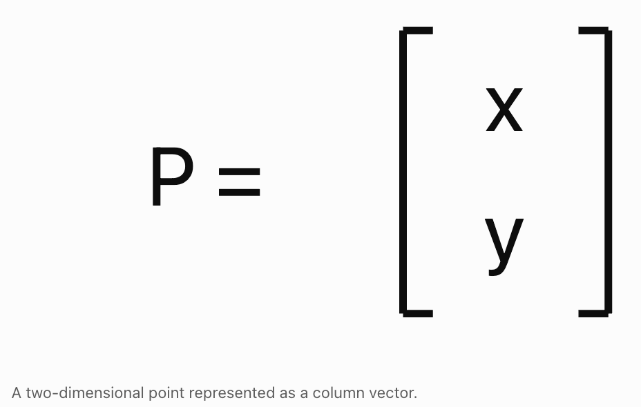
A linear transformation can be represented by a matrix M:
P′ = MP
For example, a 90° counterclockwise rotation uses:
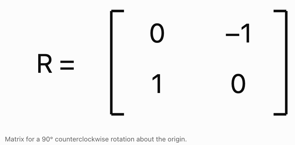
Multiplying the rotation matrix by the point vector produces:
(x, y) → (−y, x)
Common Transformation Matrices
|
Transformation |
Matrix rows |
|---|---|
|
Reflection across x-axis |
(1, 0), (0, −1) |
|
Reflection across y-axis |
(−1, 0), (0, 1) |
|
Rotation 90° counterclockwise |
(0, −1), (1, 0) |
|
Rotation 180° |
(−1, 0), (0, −1) |
|
Dilation by k |
(k, 0), (0, k) |
Each pair in the table represents one row of a 2 × 2 matrix.
General Rotation Matrix
For a counterclockwise rotation through angle θ:
R = [[cos θ, −sin θ], [sin θ, cos θ]]
Applying the matrix gives:
x′ = x cos θ − y sin θ
y′ = x sin θ + y cos θ
Worked Example: Rotation Through 30°
Rotate:
P = (4, 0)
30° counterclockwise about the origin.
Step 1: Apply the formulas
x′ = 4 cos 30° − 0 sin 30°
y′ = 4 sin 30° + 0 cos 30°
Step 2: Evaluate
x′ = 4(√3/2) = 2√3
y′ = 4(1/2) = 2
Final Answer
P′ = (2√3, 2)
Approximately:
P′ ≈ (3.46, 2)
Why Translations Are Different from Linear Matrix Transformations
A translation adds a vector to a point:
P′ = P + v
A rotation or reflection about the origin can be represented using a 2 × 2 matrix:
P′ = MP
A nonzero translation cannot be represented by multiplying ordinary two-dimensional position vectors by a 2 × 2 matrix alone.
This is because every linear transformation sends the origin to the origin, while a nonzero translation moves it.
However, translations and linear transformations can be combined using:
P′ = MP + v
This is called an affine transformation.
Example
A point is rotated 90° counterclockwise and then translated by (3, 2).
The transformation is:
P′ = RP + (3, 2)
For:
P = (2, 1)
First rotate:
RP = (−1, 2)
Then translate:
P′ = (−1, 2) + (3, 2)
P′ = (2, 4)
This mathematical form is widely used in computer graphics and robotics.
Homogeneous Coordinates
In computer graphics, translations can be included in matrix multiplication by using homogeneous coordinates.
A two-dimensional point:
P = (x, y)
is represented as:
P = (x, y, 1)
A translation by (a, b) can then be represented using the matrix:
T = [[1, 0, a], [0, 1, b], [0, 0, 1]]
Multiplying T by the homogeneous point vector gives:
(x, y, 1) → (x + a, y + b, 1)
Why This Matters
Homogeneous coordinates allow translations, rotations, reflections, and dilations to be combined into matrix operations.
This makes complex transformation sequences easier to calculate and implement in computer systems.
Vector Transformations in Three Dimensions
Translations can also be performed in three-dimensional space.
For a point:
P = (x, y, z)
and translation vector:
v = (a, b, c)
the transformation is:
(x, y, z) → (x + a, y + b, z + c)
Worked Example
A point has coordinates:
P = (2, −1, 4)
Translate it by:
v = (3, 5, −2)
Step 1: Add corresponding components
P′ = (2 + 3, −1 + 5, 4 − 2)
Final Answer
P′ = (5, 4, 2)
Finding the Magnitude of a Three-Dimensional Translation
The magnitude of:
v = (a, b, c)
is:
|v| = √(a² + b² + c²)
For:
v = (3, 5, −2)
|v| = √(3² + 5² + (−2)²)
|v| = √(9 + 25 + 4)
|v| = √38 ≈ 6.16 units

Transformations of Lines and Planes
Vectors can describe transformations of entire geometric objects, not just individual points.
Translating a Line
Suppose a line has vector equation:
r = a + td
Translate every point by vector v.
The transformed line is:
r′ = (a + v) + td
The direction vector remains unchanged.
Worked Example
Original line:
r = (1, 2, 3) + t(2, 1, −1)
Translation:
v = (4, −2, 5)
Step 1: Translate the known point
a′ = (1, 2, 3) + (4, −2, 5)
a′ = (5, 0, 8)
Step 2: Keep the direction vector
d = (2, 1, −1)
Final Answer
r′ = (5, 0, 8) + t(2, 1, −1)
The translated line is parallel to the original line.
Translating a Plane
Consider a plane:
n · r = d
where n is the plane's normal vector.
After translation by v, its equation becomes:
n · r′ = d + n · v
The normal vector does not change.
Worked Example
Original plane:
2x + y − z = 5
Translation:
v = (3, 1, 2)
The normal vector is:
n = (2, 1, −1)
Calculate:
n · v = (2)(3) + (1)(1) + (−1)(2)
n · v = 6 + 1 − 2
n · v = 5
Therefore, the translated plane is:
2x + y − z = 10
The plane's orientation remains unchanged.
Analysing Geometric Movement
Vector transformations allow us to compare displacement, distance travelled, and final position.
These quantities are related but are not identical.
Displacement
Displacement describes the change in position from start to finish.
Displacement = final position − initial position
Distance Travelled
Distance travelled is the total length of the actual path.
For several straight-line movements:
Total distance = |v₁| + |v₂| + ...
Worked Example
A person walks:
-
6 m east.
-
8 m north.
Represent the movements as:
v₁ = (6, 0)
v₂ = (0, 8)
Step 1: Calculate the displacement
v_total = (6, 0) + (0, 8)
v_total = (6, 8)
Step 2: Calculate displacement magnitude
|v_total| = √(6² + 8²)
|v_total| = 10 m
Step 3: Calculate distance travelled
Distance = 6 + 8
Distance = 14 m
Final Answers
Displacement = 10 m northeast
Distance travelled = 14 m
The distance travelled is greater because the actual path is not a straight line between the starting and ending positions.
Real-World Application: Navigation
Navigation systems use vectors to represent movement and calculate final positions.
A vehicle or aircraft may undergo a series of displacements.
The overall displacement is found by adding the movement vectors.
Worked Example
A drone begins at:
P = (10, 20, 5)
Its movements are:
v₁ = (4, 3, 2)
v₂ = (−1, 5, −1)
v₃ = (2, −4, 3)
Find the final position.

Step 1: Calculate total displacement
v_total = (4, 3, 2) + (−1, 5, −1) + (2, −4, 3)
Step 2: Combine components
x-component:
4 − 1 + 2 = 5
y-component:
3 + 5 − 4 = 4
z-component:
2 − 1 + 3 = 4
Therefore:
v_total = (5, 4, 4)
Step 3: Calculate final position
P′ = (10, 20, 5) + (5, 4, 4)
Final Answer
P′ = (15, 24, 9)
The drone finishes at coordinates (15, 24, 9).
Real-World Application: Computer Graphics and Animation
Computer graphics systems use transformations to move, rotate, resize, and orient objects.
For example, a video game character may:
-
Translate across a scene.
-
Rotate to face a target.
-
Scale during an animation.
-
Reflect in a mirror.
-
Move through a three-dimensional environment.


Why Vector Transformations Are Useful
A three-dimensional object may contain thousands of vertices.
Instead of manually recalculating each vertex, software applies the same transformation rule to every vertex.
For example:
P′ = MP + v
can represent a rotation, scaling operation, or reflection followed by a translation.
Complex animations can be produced by combining many such transformations.
Real-World Application: Robotics
Robotic arms move through a sequence of rotations and translations.
Each joint changes the position and orientation of the components attached to it.

Example
A robotic tool begins at:
P = (2, 3)
It undergoes:
-
A translation of (4, 0).
-
A 90° counterclockwise rotation about the origin.
-
A translation of (0, −2).
Find the final position.
Step 1: First translation
P′ = (2 + 4, 3 + 0)
P′ = (6, 3)
Step 2: Rotation
(6, 3) → (−3, 6)
Step 3: Second translation
P‴ = (−3, 6) + (0, −2)
Final Answer
P‴ = (−3, 4)
The order of operations is essential.
Real-World Application: Physics
In physics, vector transformations can describe changes in position and coordinate orientation.
For example:
-
Displacement vectors describe movement.
-
Rotation matrices describe changes in direction.
-
Coordinate transformations allow the same motion to be analysed from different reference frames.
-
Three-dimensional transformations help describe rigid-body motion.
Example: Changing Coordinate Orientation
Suppose a velocity vector is:
v = (5, 0)
If the coordinate axes are rotated 90° counterclockwise while the physical velocity remains unchanged, the velocity's components in the new coordinate system become:
v_new = (0, −5)
This is different from actively rotating the velocity vector itself 90° counterclockwise in a fixed coordinate system, which would give:
v_rotated = (0, 5)
Important Distinction
An active transformation changes the geometric object or vector.
A passive transformation changes the coordinate system used to describe it.
This distinction becomes important in advanced physics, engineering, and robotics.
Multi-Step Transformation Problems
Worked Example: Translation, Reflection, and Rotation
A point begins at:
P = (3, 1)
It undergoes:
-
Translation by (−2, 4).
-
Reflection across the y-axis.
-
Rotation by 90° clockwise about the origin.
Find the final coordinates.
Step 1: Translate
P′ = (3 − 2, 1 + 4)
P′ = (1, 5)
Step 2: Reflect Across the y-Axis
Rule:
(x, y) → (−x, y)
Therefore:
P″ = (−1, 5)
Step 3: Rotate 90° Clockwise
Rule:
(x, y) → (y, −x)
Therefore:
P‴ = (5, 1)
Final Answer
P‴ = (5, 1)
Verification
Each transformation has been applied in the stated order.
Reversing the order could produce a different final point.
Worked Example: Transforming a Triangle
A triangle has vertices:
A = (1, 1)
B = (4, 1)
C = (2, 3)
The triangle is:
-
Translated by (2, 1).
-
Rotated 180° about the origin.
Find the final coordinates.
Step 1: Translate Each Vertex
A′ = (3, 2)
B′ = (6, 2)
C′ = (4, 4)
Step 2: Apply the 180° Rotation
Rule:
(x, y) → (−x, −y)
Therefore:
A″ = (−3, −2)
B″ = (−6, −2)
C″ = (−4, −4)
Final Answer
The transformed triangle has vertices:
A″ = (−3, −2)
B″ = (−6, −2)
C″ = (−4, −4)
Geometric Interpretation
Both translations and rotations are rigid transformations.
Therefore, the final triangle is congruent to the original triangle.
Its side lengths, angles, perimeter, and area remain unchanged.
Analysing Transformation Properties
Different transformations preserve different geometric properties.
|
Property |
Translation |
Rotation |
Reflection |
Dilation |
|---|---|---|---|---|
|
Shape |
Preserved |
Preserved |
Preserved |
Preserved |
|
Side lengths |
Preserved |
Preserved |
Preserved |
Scaled |
|
Angles |
Preserved |
Preserved |
Preserved |
Preserved |
|
Area |
Preserved |
Preserved |
Preserved |
Scaled by k² |
|
Orientation |
Preserved |
Preserved |
Reversed |
Preserved if k > 0 |
|
Parallelism |
Preserved |
Preserved |
Preserved |
Preserved |
Orientation
Orientation describes the ordering of points around a figure.
For example, a triangle's vertices may be arranged clockwise or counterclockwise.
Translations and rotations preserve this ordering.
Reflections reverse it.
A dilation with a negative scale factor centred at a point corresponds to a positive dilation combined with a 180° rotation, so it preserves orientation in two dimensions.
Choosing the Correct Transformation Method
|
Problem |
Recommended method |
|---|---|
|
Translate a point |
Add the translation vector |
|
Translate a figure |
Add the vector to every vertex |
|
Find a translation vector |
Subtract original coordinates from image coordinates |
|
Combine translations |
Add the translation vectors |
|
Reverse a translation |
Use the negative vector |
|
Calculate displacement |
Final position − initial position |
|
Calculate movement distance |
Find the magnitude of the displacement vector |
|
Reflect across an axis |
Apply the coordinate reflection rule |
|
Rotate around the origin |
Apply a coordinate rule or rotation matrix |
|
Dilate from the origin |
Multiply coordinates by the scale factor |
|
Combine transformations |
Apply each transformation in the correct order |
|
Transform a line |
Translate a known point; preserve its direction |
|
Transform a plane by translation |
Adjust its constant using the normal vector |
|
Model complex movement |
Use affine transformations or homogeneous coordinates |
General Problem-Solving Strategy
-
Identify the original point or figure.
-
Determine the type of transformation.
-
Write the transformation rule.
-
Apply the rule to each relevant point.
-
If several transformations are involved, follow the stated order.
-
Calculate the final coordinates.
-
Check whether the expected geometric properties are preserved.
-
Interpret the movement in the original context.
-
Verify the result using an inverse transformation or coordinate substitution when appropriate.
Common Mistakes
Confusing a point with a translation vector
A point represents a location, while a translation vector represents movement.
Subtracting instead of adding during translation
Translations are performed by adding the translation vector to the point coordinates.
Ignoring negative components
Negative components indicate movement left or downward in the standard coordinate system.
Translating only one vertex of a figure
Every vertex must undergo the same translation.
Confusing distance travelled with displacement
Displacement is the net change in position, while distance travelled measures the total path length.
Adding vector magnitudes instead of vector components
The combined translation is found by adding corresponding components.
Using the wrong reflection rule
Different reflection lines require different coordinate rules.
Confusing clockwise and counterclockwise rotations
A 90° clockwise rotation differs from a 90° counterclockwise rotation.
Forgetting the centre of rotation
Rotation rules depend on the centre of rotation.
Assuming transformation order never matters
Pure translations commute, but combinations of different transformations generally do not.
Confusing congruence and similarity
Rigid transformations preserve size and shape, while dilations preserve shape but generally change size.
Using an incorrect scale factor
A dilation by k multiplies coordinates relative to its centre by k.
Assuming a 2 × 2 matrix can represent every translation
Nonzero translations require vector addition or an augmented matrix representation.
Applying matrix transformations in the wrong order
Matrix multiplication is generally not commutative.
Confusing active and passive transformations
Moving a vector and changing the coordinate system are different operations.
Failing to check geometric properties
Translations and rotations should preserve lengths and angles.
Rounding intermediate calculations too early
Keep exact values whenever possible and round only the final result.
Key Terms
-
Vector: A quantity with magnitude and direction.
-
Position Vector: A vector describing the location of a point relative to the origin.
-
Translation: A transformation that moves every point by the same displacement.
-
Translation Vector: A vector describing the distance and direction of a translation.
-
Geometric Transformation: A rule mapping points of a figure to new positions.
-
Preimage: The original figure before a transformation.
-
Image: The figure produced by a transformation.
-
Coordinate Rule: A mathematical rule describing how coordinates change.
-
Rigid Transformation: A transformation preserving distances and angles.
-
Isometry: Another name for a distance-preserving transformation.
-
Reflection: A transformation that flips a figure across a line.
-
Line of Reflection: The line across which a figure is reflected.
-
Rotation: A transformation that turns a figure around a fixed point.
-
Centre of Rotation: The fixed point around which a rotation occurs.
-
Angle of Rotation: The angle through which a figure is rotated.
-
Dilation: A transformation that changes the size of a figure using a scale factor.
-
Scale Factor: A number determining the enlargement or reduction of a figure.
-
Composition of Transformations: A sequence of two or more transformations.
-
Inverse Transformation: A transformation that reverses another transformation.
-
Identity Transformation: A transformation that leaves every point unchanged.
-
Displacement: The change in position from an initial point to a final point.
-
Distance Travelled: The total length of the path followed.
-
Magnitude: The length or size of a vector.
-
Direction Angle: An angle describing the direction of a vector relative to a reference axis.
-
Matrix: A rectangular arrangement of numbers used in mathematical operations.
-
Transformation Matrix: A matrix representing a geometric transformation.
-
Linear Transformation: A transformation preserving vector addition and scalar multiplication.
-
Affine Transformation: A transformation combining a linear transformation with a translation.
-
Homogeneous Coordinates: An extended coordinate system allowing translations to be represented using matrices.
-
Commutative Property: A property stating that changing the order of operations does not change the result.
-
Congruence: A relationship between figures with the same shape and size.
-
Similarity: A relationship between figures with the same shape and proportional dimensions.
-
Orientation: The clockwise or counterclockwise ordering of points in a figure.
-
Active Transformation: A transformation that changes the position or orientation of an object.
-
Passive Transformation: A change in the coordinate system used to describe an object.
-
Three-Dimensional Translation: A movement described by changes in x-, y-, and z-coordinates.
-
Geometric Modelling: Using mathematical representations to describe shapes, positions, and movement.
Key Takeaways
-
Vector transformations provide a mathematical method for describing geometric movement.
-
A translation moves every point of a figure by the same vector.
-
In two dimensions, a translation by (a, b) follows the rule (x, y) → (x + a, y + b).
-
In three dimensions, a translation by (a, b, c) follows the rule (x, y, z) → (x + a, y + b, z + c).
-
A translation vector can be found by subtracting the original coordinates from the transformed coordinates.
-
The magnitude of a translation vector gives the straight-line displacement distance.
-
Multiple translations can be combined by adding their vectors.
-
The order of pure translations does not affect the final result.
-
An inverse translation uses the negative of the original translation vector.
-
Reflections reverse orientation while preserving distances and angles.
-
Rotations preserve distances, angles, and orientation.
-
Dilations change size according to a scale factor.
-
Different transformation types can be combined into a composition.
-
The order of transformations generally matters.
-
Matrices provide a systematic way to represent rotations, reflections, and dilations.
-
Affine transformations combine matrix operations with vector translations.
-
Homogeneous coordinates allow translations to be represented through matrix multiplication.
-
Translations can be applied to points, figures, lines, and planes.
-
Vector addition allows us to analyse total displacement from several movements.
-
Displacement and distance travelled are different quantities.
-
Vector transformations are widely used in navigation, robotics, physics, animation, and computer graphics.
-
The central skill is applying vector rules to describe, combine, analyse, and model geometric transformations in two and three dimensions.
Check Your Understanding
Recall and Understanding
-
Define a translation and explain how a vector describes its movement.
-
Explain the difference between a preimage and an image.
-
State the coordinate rule for a translation by vector (a, b).
-
Explain why the order of two translations does not affect the final result.
-
Describe the difference between a rigid transformation and a dilation.
Application
-
Translate P = (3, −2) by vector v = (5, 4). Find P′.
-
A triangle has vertices A = (1, 2), B = (4, 2), and C = (2, 5). Translate it by (−3, 1).
-
Point P = (−4, 6) is translated to P′ = (2, 1). Find the translation vector.
-
Combine the translations v₁ = (4, 3), v₂ = (−2, 5), and v₃ = (1, −4).
-
Rotate P = (5, 2) by 90° counterclockwise about the origin.
Analysis and Challenge
-
Point P = (2, 3) is translated by (4, −1), then reflected across the y-axis. Find its final coordinates.
-
Point P = (3, −1) is rotated 180° about the origin and then translated by (2, 5). Find its final coordinates.
-
A robot begins at (5, 2, 1) and moves by vectors (3, 4, 2), (−2, 1, −3), and (4, −5, 1). Find its final position and the magnitude of its total displacement.
-
A line has equation r = (1, 2, 3) + t(2, −1, 4). Translate it by vector (3, 5, −2). Write the new line equation.
-
A plane has equation 2x − y + 3z = 7. Translate it by vector (1, 2, −1). Determine the equation of the translated plane.
Final Summary
Vector transformations provide a systematic mathematical framework for describing how geometric objects move and change in space.
Translations are represented by adding displacement vectors to points. Multiple translations can be combined through vector addition, and inverse translations reverse the original movement.
Reflections, rotations, and dilations can be described using coordinate rules and matrices.
More complex transformations can be modelled using affine transformations, which combine linear transformations with translations.
The order of operations is important when several different transformations are applied.
Vector transformations are useful for describing geometric movement, analysing displacement, modelling rigid-body motion, and performing calculations in computer graphics, engineering, robotics, and navigation.
The central principle is that geometric transformations can be represented using mathematical operations on vectors and coordinates, allowing us to describe movement precisely, combine transformations, and predict the resulting position and orientation of objects.
5. Applications of Vector Geometry
Learning outcomes
- I can solve engineering applications using vectors.
- I can analyse forces in equilibrium.
- I can model motion in two and three dimensions.
- I can solve optimisation problems involving vectors.
- I can communicate vector reasoning clearly.
Applications of Vector Geometry
Introduction to Vector Geometry in Engineering
Vectors are essential mathematical tools in engineering, physics, architecture, robotics, and transportation.
Many real-world problems involve quantities that have both magnitude and direction. Examples include forces acting on a bridge, the velocity of an aircraft, the movement of a robotic arm, and the tension in a cable supporting a structure.
Vector geometry allows these situations to be represented mathematically and analysed systematically.
Engineers use vectors to:
-
Calculate the combined effects of several forces.
-
Determine whether a structure or object is in equilibrium.
-
Model displacement, velocity, and acceleration.
-
Describe motion in two and three dimensions.
-
Calculate moments and rotational effects.
-
Find shortest distances and optimal directions.
-
Minimise forces, travel distances, or energy requirements.
-
Communicate engineering solutions using equations, diagrams, and units.
The central principle is that vector methods transform complex physical situations into mathematical models that can be calculated, verified, and interpreted.


Reviewing Essential Vector Concepts
Before solving engineering applications, it is important to understand the mathematical properties of vectors.
A vector has:
-
Magnitude: Its size or length.
-
Direction: The orientation in which it acts.
In two dimensions, a vector can be written:
A = (Aₓ, Aᵧ)
In three dimensions:
A = (Aₓ, Aᵧ, A_z)
The components describe how much of the vector acts along each coordinate axis.
Magnitude of a Vector
For a two-dimensional vector:
|A| = √(Aₓ² + Aᵧ²)
For a three-dimensional vector:
|A| = √(Aₓ² + Aᵧ² + A_z²)
Worked Example: Magnitude of a Force
A force is represented by:
F = (30, 40) N
Calculate its magnitude.
|F| = √(30² + 40²)
|F| = √(900 + 1600)
|F| = √2500
|F| = 50 N
The force has a magnitude of 50 N.
Unit Vectors
A unit vector has a magnitude of 1.
For a nonzero vector A:
u = A/|A|
Unit vectors are useful because they describe direction independently of magnitude.
For F = (30, 40):
u = (30/50, 40/50)
u = (0.6, 0.8)
Therefore, a force of magnitude 100 N in this direction is:
F = 100(0.6, 0.8)
F = (60, 80) N
Resolving Forces into Components
Engineering forces often act at angles rather than directly along coordinate axes.
To analyse these forces, they can be resolved into horizontal and vertical components.
For a force F acting at angle θ measured counterclockwise from the positive x-axis:
Fₓ = F cos θ
Fᵧ = F sin θ
The vector is:
F = (F cos θ, F sin θ)
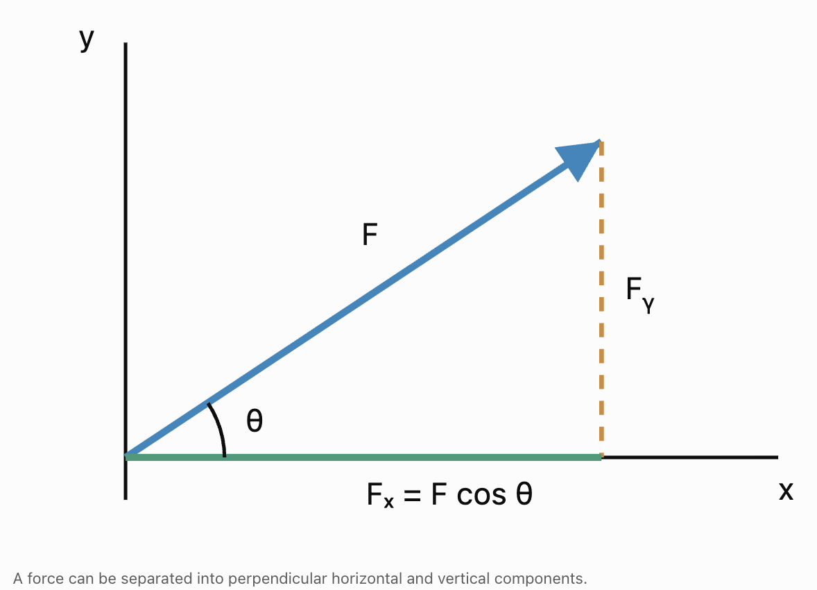
Worked Example: Pulling a Load
A worker pulls a load with a force of 200 N at 30° above the horizontal.
Calculate the horizontal and vertical components.
Step 1: Horizontal component
Fₓ = 200 cos 30°
Fₓ = 200(0.8660)
Fₓ ≈ 173.2 N
Step 2: Vertical component
Fᵧ = 200 sin 30°
Fᵧ = 200(0.5)
Fᵧ = 100 N
Interpretation
The applied force produces:
-
Approximately 173.2 N horizontally.
-
100 N upward.
The upward component reduces the normal force on the load if the load remains on a horizontal surface without other vertical forces.
Important Observation
The horizontal and vertical components are not separate additional forces. They are mathematical representations of the original force.
Resultant Forces
When several forces act on an object, their combined effect is represented by the resultant force.
The resultant is the vector sum:
F_net = F₁ + F₂ + F₃ + ...
For two-dimensional forces:
F_net = (ΣFₓ, ΣFᵧ)
where Σ means the sum of all components.
Worked Example: Three Forces
Three forces act on an object:
F₁ = (40, 20) N
F₂ = (−15, 30) N
F₃ = (−10, −25) N
Calculate the resultant force.
Step 1: Add horizontal components
ΣFₓ = 40 − 15 − 10
ΣFₓ = 15 N
Step 2: Add vertical components
ΣFᵧ = 20 + 30 − 25
ΣFᵧ = 25 N
Step 3: Write the resultant
F_net = (15, 25) N
Step 4: Calculate its magnitude
|F_net| = √(15² + 25²)
= √850
|F_net| ≈ 29.2 N
Step 5: Determine its direction
tan θ = 25/15
θ ≈ 59.0°
Final Answer
The resultant force is approximately:
29.2 N at 59.0° above the positive x-axis.
Forces in Equilibrium
An object is in translational equilibrium when the vector sum of all forces acting on it is zero.
ΣF = 0
In two dimensions:
ΣFₓ = 0
ΣFᵧ = 0
In three dimensions:
ΣFₓ = 0
ΣFᵧ = 0
ΣF_z = 0
An object in translational equilibrium has zero acceleration.
It may be stationary or moving with constant velocity.
Static and Dynamic Equilibrium
-
Static equilibrium: The object remains at rest.
-
Dynamic equilibrium: The object moves with constant velocity.
For a rigid body to be in complete equilibrium, the net torque must also be zero:
Στ = 0
This prevents angular acceleration.
Worked Example: Finding an Equilibrant Force
An object experiences:
F₁ = (50, 20) N
F₂ = (−30, 10) N
Find the third force required for equilibrium.
Step 1: Write the equilibrium condition
F₁ + F₂ + F₃ = 0
Step 2: Rearrange
F₃ = −(F₁ + F₂)
Step 3: Add the known forces
F₁ + F₂ = (50 − 30, 20 + 10)
= (20, 30) N
Step 4: Reverse the resultant
F₃ = (−20, −30) N
Verification
ΣFₓ = 50 − 30 − 20 = 0
ΣFᵧ = 20 + 10 − 30 = 0
The object is in translational equilibrium.
Engineering Application: Cable Tension
Suspended structures often use cables to support loads.
Examples include:
-
Suspension bridges.
-
Cranes.
-
Lighting fixtures.
-
Communication towers.
-
Roof supports.
Cable tensions act along the directions of the cables.


Worked Example: Two Supporting Cables
A 600 N load hangs from two cables.
The left cable makes an angle of 30° above the horizontal.
The right cable makes an angle of 60° above the horizontal.
Find the tensions T₁ and T₂.
Assume the load is stationary and the cables are massless.
Step 1: Identify the forces
Left cable:
T₁ = (−T₁ cos 30°, T₁ sin 30°)
Right cable:
T₂ = (T₂ cos 60°, T₂ sin 60°)
Weight:
W = (0, −600) N
Step 2: Apply horizontal equilibrium
−T₁ cos 30° + T₂ cos 60° = 0
T₂ cos 60° = T₁ cos 30°
T₂(0.5) = T₁(0.8660)
Therefore:
T₂ = 1.732T₁
Step 3: Apply vertical equilibrium
T₁ sin 30° + T₂ sin 60° = 600
0.5T₁ + 0.8660T₂ = 600
Step 4: Substitute
0.5T₁ + 0.8660(1.732T₁) = 600
0.5T₁ + 1.5T₁ = 600
2T₁ = 600
T₁ = 300 N
Step 5: Calculate T₂
T₂ = 1.732(300)
T₂ ≈ 519.6 N
Final Answer
Left cable tension = 300 N
Right cable tension ≈ 519.6 N
Engineering Interpretation
The right cable experiences greater tension because of its orientation.
Cable angle strongly affects the forces experienced by supporting structures.
Engineers must account for these differences when selecting cables and designing attachment points.
Three-Dimensional Force Equilibrium
Many engineering structures cannot be accurately represented using only two dimensions.
For example, a crane may support a load using cables extending in several spatial directions.
Each force must then be represented using three components.
Worked Example: Equilibrium in Three Dimensions
Three forces act on a joint:
F₁ = (100, 50, −20) N
F₂ = (−40, 30, 70) N
F₃ = (−20, −60, −10) N
Find the fourth force required for equilibrium.
Step 1: Add the known forces
ΣFₓ = 100 − 40 − 20 = 40 N
ΣFᵧ = 50 + 30 − 60 = 20 N
ΣF_z = −20 + 70 − 10 = 40 N
Therefore:
F_known = (40, 20, 40) N
Step 2: Find the balancing force
F₄ = −F_known
F₄ = (−40, −20, −40) N
Step 3: Calculate its magnitude
|F₄| = √(40² + 20² + 40²)
= √(1600 + 400 + 1600)
= √3600
|F₄| = 60 N
Final Answer
A force of 60 N in the direction (−40, −20, −40) is required to balance the other forces.
Torque and Rotational Equilibrium
Forces can produce rotation as well as translation.
The rotational effect of a force about a point is called torque or moment.
Torque is calculated using the cross product:
τ = r × F
where:
-
τ is the torque vector.
-
r is the position vector from the pivot to the force application point.
-
F is the applied force.
The magnitude is:
|τ| = |r||F| sin θ
where θ is the angle between r and F.

Worked Example: Torque on a Lever
A 150 N force acts perpendicular to a lever at a distance of 0.40 m from the pivot.
Calculate the torque magnitude.
Step 1: Write the formula
|τ| = |r||F| sin θ
Step 2: Substitute
|τ| = (0.40)(150) sin 90°
Step 3: Calculate
|τ| = 60(1)
|τ| = 60 N·m
Rotational Equilibrium
For an object to have no angular acceleration:
Στ = 0
For a rigid body at rest, both conditions must hold:
ΣF = 0
Στ = 0
Worked Example: Balancing a Beam
A horizontal beam is supported at its centre.
A 200 N downward force acts 2 m to the left of the pivot.
How far to the right must a 100 N downward force act to balance the torques?
Assume the beam's own weight is already balanced.
Step 1: Calculate the left torque magnitude
τ₁ = 200(2)
τ₁ = 400 N·m
Step 2: Write the balancing condition
100d = 400
Step 3: Solve
d = 4 m
Final Answer
The 100 N force must act 4 m to the right of the pivot.
Modelling Motion Using Vectors
Motion can be described using position, displacement, velocity, and acceleration vectors.
Position Vector
The position of an object is:
r(t)
where t represents time.
Displacement Vector
Between times t₁ and t₂:
Δr = r(t₂) − r(t₁)
Average Velocity
v_avg = Δr/Δt
Instantaneous Velocity
v(t) = dr/dt
Instantaneous Acceleration
a(t) = dv/dt
These equations apply to motion in two or three dimensions.
Motion with Constant Velocity
For an object moving with constant velocity:
r(t) = r₀ + vt
where:
-
r₀ is the initial position vector.
-
v is the constant velocity vector.
-
t is elapsed time.
Worked Example: Two-Dimensional Motion
A vehicle begins at:
r₀ = (10, 20) m
Its velocity is:
v = (4, 3) m/s
Find its position after 6 seconds.
Step 1: Write the equation
r(t) = r₀ + vt
Step 2: Substitute
r(6) = (10, 20) + 6(4, 3)
Step 3: Calculate the displacement
6(4, 3) = (24, 18)
Step 4: Find the final position
r(6) = (10 + 24, 20 + 18)
Final Answer
r(6) = (34, 38) m
Calculate the Speed
|v| = √(4² + 3²)
|v| = 5 m/s
The vehicle moves at a constant speed of 5 m/s.
Motion with Constant Acceleration
For constant acceleration:
v(t) = v₀ + at
r(t) = r₀ + v₀t + ½at²
These equations can be applied component by component.
Worked Example: Two-Dimensional Accelerated Motion
An object begins at:
r₀ = (0, 0) m
with initial velocity:
v₀ = (5, 10) m/s
Its constant acceleration is:
a = (2, −4) m/s²
Find its position and velocity after 3 seconds.
Step 1: Calculate velocity
v(3) = (5, 10) + 3(2, −4)
v(3) = (5, 10) + (6, −12)
v(3) = (11, −2) m/s
Step 2: Calculate position
r(3) = (0, 0) + 3(5, 10) + ½(2, −4)(3²)
Step 3: Calculate each term
3(5, 10) = (15, 30)
½(2, −4)(9) = (9, −18)
Step 4: Add the vectors
r(3) = (15, 30) + (9, −18)
Final Answer
r(3) = (24, 12) m
v(3) = (11, −2) m/s
Interpretation
After three seconds, the object is 24 m horizontally and 12 m vertically from its starting position.
Its vertical velocity is negative, indicating downward motion at that instant.
Projectile Motion as a Vector Problem
Projectile motion is a common example of two-dimensional motion.
Ignoring air resistance, a projectile experiences constant downward acceleration due to gravity.
Using upward as the positive y-direction:
a = (0, −g)
where:
g ≈ 9.81 m/s²
The initial velocity can be resolved into:
v₀ = (v₀ cos θ, v₀ sin θ)
The position equations are:
x(t) = x₀ + (v₀ cos θ)t
y(t) = y₀ + (v₀ sin θ)t − ½gt²

Worked Example: Projectile Motion
A ball is launched from ground level at 20 m/s and 30° above the horizontal.
Find its position after 2 seconds.
Assume no air resistance.
Step 1: Calculate the initial velocity components
v₀ₓ = 20 cos 30°
v₀ₓ ≈ 17.32 m/s
v₀ᵧ = 20 sin 30°
v₀ᵧ = 10 m/s
Step 2: Calculate horizontal position
x = 17.32(2)
x ≈ 34.64 m
Step 3: Calculate vertical position
y = 10(2) − ½(9.81)(2²)
y = 20 − 19.62
y = 0.38 m
Final Answer
After 2 seconds, the ball is approximately:
r(2) = (34.64, 0.38) m
The ball is just above its original launch height.
Motion in Three Dimensions
Three-dimensional motion is represented using three coordinate functions.
r(t) = (x(t), y(t), z(t))
Velocity and acceleration are:
v(t) = (dx/dt, dy/dt, dz/dt)
a(t) = (d²x/dt², d²y/dt², d²z/dt²)
Worked Example: Drone Motion
A drone follows the position function:
r(t) = (2t, 3t², 10 + t³)
where position is measured in metres and time in seconds.
Find its position, velocity, and acceleration at t = 2 s.
Step 1: Calculate position
r(2) = (2(2), 3(2²), 10 + 2³)
r(2) = (4, 12, 18) m
Step 2: Differentiate to find velocity
v(t) = (2, 6t, 3t²)
At t = 2:
v(2) = (2, 12, 12) m/s
Step 3: Differentiate to find acceleration
a(t) = (0, 6, 6t)
At t = 2:
a(2) = (0, 6, 12) m/s²
Interpretation
At t = 2 s:
-
The drone is at position (4, 12, 18) m.
-
Its velocity is (2, 12, 12) m/s.
-
Its acceleration is (0, 6, 12) m/s².
The drone is accelerating in both the y- and z-directions.
Relative Velocity
Relative velocity describes the motion of one object as observed from another moving object.
If two objects have velocities v_A and v_B:
v_A relative to B = v_A − v_B
This is useful in:
-
Aircraft navigation.
-
Ship navigation.
-
Vehicle tracking.
-
Robotics.
-
Collision analysis.
Worked Example: Relative Motion
Vehicle A travels with velocity:
v_A = (20, 5) m/s
Vehicle B travels with velocity:
v_B = (12, −3) m/s
Find the velocity of A relative to B.
Step 1: Subtract
v_AB = v_A − v_B
v_AB = (20, 5) − (12, −3)
Step 2: Simplify
v_AB = (8, 8) m/s
Step 3: Calculate magnitude
|v_AB| = √(8² + 8²)
= √128
|v_AB| ≈ 11.31 m/s
Interpretation
From Vehicle B's reference frame, Vehicle A moves at approximately 11.31 m/s in a direction 45° above the positive x-axis.
Engineering Optimisation Using Vectors
Optimisation involves finding the best possible solution under given conditions.
Engineers may want to:
-
Minimise the distance travelled.
-
Minimise cable tension.
-
Maximise the useful component of a force.
-
Minimise energy consumption.
-
Find the closest point on a line or plane.
-
Determine an optimal movement direction.
Vectors provide mathematical methods for solving these problems.
Optimising the Direction of a Force
The dot product describes how much of a force acts along a chosen direction.
For force F and unit direction vector u:
F · u = |F| cos θ
This gives the signed component of F along u.
For a force of fixed magnitude, the component in a desired direction is greatest when the force acts directly along that direction.
Worked Example: Maximising Useful Force
A worker applies a 100 N force to move a cart horizontally.
Compare the horizontal force component when the force acts at:
-
0° above the horizontal.
-
30° above the horizontal.
-
60° above the horizontal.
Use:
Fₓ = F cos θ
|
Angle |
Horizontal component |
|---|---|
|
0° |
100 N |
|
30° |
86.6 N |
|
60° |
50 N |
Conclusion
The horizontal component is greatest when the force acts horizontally.
Maximum horizontal component = 100 N
Engineering Interpretation
If the objective is to maximise the force component along a specified direction, the force should align with that direction.
In real applications, friction, geometry, accessibility, and safety may impose additional constraints.
Optimising Work Done
Work done by a constant force is calculated using the dot product:
W = F · d
where:
-
W is work done.
-
F is the force vector.
-
d is the displacement vector.
Equivalently:
W = |F||d| cos θ
Worked Example
A 50 N force acts on an object that moves 8 m.
Calculate the work done when the force acts at:
-
0° to the displacement.
-
60° to the displacement.
-
90° to the displacement.
Case 1: θ = 0°
W = 50(8) cos 0°
W = 400 J
Case 2: θ = 60°
W = 50(8) cos 60°
W = 200 J
Case 3: θ = 90°
W = 50(8) cos 90°
W = 0 J
Conclusion
For fixed force and displacement magnitudes, work is maximised when the force acts in the same direction as the displacement.
Finding the Shortest Distance to a Line
The shortest distance from a point to a line is measured perpendicular to the line.
Vector projection provides an efficient method for calculating this distance.
Suppose a line is:
r = a + td
and a point P has position vector p.
Construct:
w = p − a
The component of w parallel to the line is:
w_parallel = [(w · d)/(d · d)]d
The perpendicular component is:
w_perp = w − w_parallel
Therefore:
Distance = |w_perp|
Worked Example
Find the shortest distance from:
P = (3, 4)
to the line:
r = (1, 1) + t(2, 0)
Step 1: Find the vector from the line to P
w = (3, 4) − (1, 1)
w = (2, 3)
Step 2: Identify the direction vector
d = (2, 0)
Step 3: Calculate the projection coefficient
(w · d)/(d · d)
= [(2)(2) + (3)(0)]/(2² + 0²)
= 4/4
= 1
Step 4: Calculate the parallel component
w_parallel = 1(2, 0)
w_parallel = (2, 0)
Step 5: Calculate the perpendicular component
w_perp = (2, 3) − (2, 0)
w_perp = (0, 3)
Step 6: Calculate distance
|w_perp| = √(0² + 3²)
Final Answer
Shortest distance = 3 units
The nearest point on the line is (3, 1).
Finding the Closest Point on a Plane
The closest point on a plane lies along a line perpendicular to the plane.
For a plane:
n · r = d
and a point P with position vector p, the closest point q is:
q = p − [(n · p − d)/(n · n)]n
Worked Example
Find the closest point on the plane:
z = 2
to:
P = (3, 4, 7)
The normal vector is:
n = (0, 0, 1)
The plane constant is:
d = 2
Step 1: Calculate the numerator
n · p − d = 7 − 2 = 5
Step 2: Calculate the denominator
n · n = 1
Step 3: Apply the formula
q = (3, 4, 7) − 5(0, 0, 1)
Final Answer
q = (3, 4, 2)
Calculate the Distance
P − q = (0, 0, 5)
Therefore:
Distance = 5 units
Engineering Application
This method can be used to calculate the shortest distance between a moving object and a flat surface.
Optimising Cable Tension
Cable tension depends on the direction of the cable.
Consider a load W supported symmetrically by two cables, each making an angle θ above the horizontal.
If the cables have equal tension T:
2T sin θ = W
Therefore:
T = W/(2 sin θ)
Worked Example
A 1000 N load is supported by two identical cables.
Calculate the tension in each cable when:
-
θ = 30°.
-
θ = 45°.
-
θ = 60°.
|
Cable angle above horizontal |
Tension in each cable |
|---|---|
|
30° |
1000 N |
|
45° |
≈ 707.1 N |
|
60° |
≈ 577.4 N |
Interpretation
As the cables become steeper, the tension required to support the same load decreases.
Within this simplified model, the lowest tension occurs when the cables are vertical.
However, real structures have constraints involving cable placement, available space, connection strength, and structural stability.

Optimising a Travel Route
Vector geometry can also be used to compare possible routes.
Worked Example
A robot must travel from:
A = (0, 0)
to:
B = (6, 8)
Route 1: Move 6 m east, then 8 m north.
Route 2: Move directly from A to B.
Calculate the distance for each route.
Route 1
Distance = 6 + 8
Distance = 14 m
Route 2
Displacement vector:
AB = (6, 8)
Distance = √(6² + 8²)
Distance = √100
Distance = 10 m
Comparison
|
Route |
Distance |
|---|---|
|
East then north |
14 m |
|
Direct route |
10 m |
Conclusion
The direct route is 4 m shorter.
This is the shortest possible route between the two points in unobstructed Euclidean space.
Real-world route optimisation may also require considering obstacles, terrain, speed limits, and energy costs.
Real-World Application: Bridge Engineering
Bridges contain structural members that transmit forces through a framework.
Engineers use vector analysis to calculate forces acting at joints and supports.
For a joint in static equilibrium:
ΣF = 0
For the entire bridge structure, rotational equilibrium must also be satisfied:
Στ = 0

Example: Forces at a Joint
Suppose two horizontal forces act on a bridge joint:
F₁ = (800, 0) N
F₂ = (−500, 0) N
A third force must maintain equilibrium.
F₃ = −(F₁ + F₂)
F₃ = −(300, 0)
F₃ = (−300, 0) N
The third force must act 300 N to the left.
In real truss analysis, engineers calculate member forces using joint equilibrium, structural geometry, and support conditions.
Real-World Application: Robotics and Motion Planning
Robots use vectors to represent position, velocity, acceleration, and forces.
A robotic arm may need to move from one location to another while avoiding obstacles.

Worked Example: Moving a Robotic Tool
A robotic tool begins at:
A = (1, 2, 3) m
Its target is:
B = (5, 6, 6) m
Find the displacement vector and straight-line distance.
Step 1: Calculate displacement
AB = B − A
AB = (5 − 1, 6 − 2, 6 − 3)
AB = (4, 4, 3) m
Step 2: Calculate distance
|AB| = √(4² + 4² + 3²)
= √(16 + 16 + 9)
= √41
|AB| ≈ 6.40 m
Step 3: Calculate the unit direction vector
u = AB/|AB|
u = (4/√41, 4/√41, 3/√41)
Approximately:
u ≈ (0.625, 0.625, 0.469)
Interpretation
The unit vector gives the direction of the shortest straight-line movement from the starting point to the target.
A real robotic arm must also satisfy joint limits, collision constraints, and mechanical requirements.
Real-World Application: Aircraft Navigation
Aircraft velocity is affected by wind.
The aircraft's velocity relative to the ground is:
v_ground = v_aircraft + v_wind
Worked Example
An aircraft travels east at 200 km/h relative to the surrounding air.
The wind blows north at 50 km/h.
Find the ground velocity.
Step 1: Represent the vectors
v_aircraft = (200, 0) km/h
v_wind = (0, 50) km/h
Step 2: Add the vectors
v_ground = (200, 50) km/h
Step 3: Calculate ground speed
|v_ground| = √(200² + 50²)
= √42500
|v_ground| ≈ 206.2 km/h
Step 4: Calculate direction
tan θ = 50/200
θ ≈ 14.0°
Final Answer
Ground speed ≈ 206.2 km/h
Direction ≈ 14.0° north of east
Interpretation
The wind changes both the speed and direction of the aircraft relative to the ground.
Pilots must account for wind when selecting headings.
Real-World Application: Computer Graphics and Engineering Design
Computer-aided design systems use vectors to represent three-dimensional objects.
Vectors can describe:
-
Surface directions.
-
Surface normals.
-
Distances between components.
-
Object movement.
-
Rotational effects.
-
Intersections between geometric surfaces.
The cross product is particularly useful for calculating surface normals.
Given two nonparallel vectors A and B lying in a plane:
n = A × B
The resulting vector is perpendicular to the plane.

Example: Surface Normal
Two vectors lie along a surface:
A = (2, 0, 0)
B = (0, 3, 0)
Calculate a normal vector.
A × B = (0, 0, 6)
Therefore:
n = (0, 0, 6)
The corresponding unit normal is:
u = (0, 0, 1)
This indicates that the surface faces in the positive z-direction according to the chosen vector order.
Communicating Vector Reasoning Clearly
Engineering solutions must be mathematically correct and understandable to other people.
A complete vector solution should communicate:
-
The physical situation.
-
The coordinate system.
-
The known quantities.
-
The assumptions.
-
The relevant vector equations.
-
The calculation steps.
-
The final result with units.
-
The physical meaning of the result.
Example of Clear Mathematical Communication
Problem: Find the force required to balance two forces acting on a joint.
Given:
F₁ = (40, 20) N
F₂ = (−10, 30) N
Method:
For equilibrium:
F₁ + F₂ + F₃ = 0
Therefore:
F₃ = −(F₁ + F₂)
Calculation:
F₁ + F₂ = (30, 50) N
F₃ = (−30, −50) N
Magnitude:
|F₃| = √(30² + 50²)
|F₃| ≈ 58.3 N
Conclusion:
A force of approximately 58.3 N, directed leftward and downward with components (−30, −50) N, is required to maintain translational equilibrium.
Verification:
(40, 20) + (−10, 30) + (−30, −50) = (0, 0)
The equilibrium condition is satisfied.
Why This Format Is Effective
The solution identifies the mathematical principle, shows how it is applied, and verifies the result.
This is the standard of communication expected in technical engineering work.
Multi-Step Engineering Problem: Cable Force and Motion
A 20 kg object is initially stationary.
Two forces act on it:
F₁ = (80, 40) N
F₂ = (−20, 60) N
Assume the forces are constant and these are the only forces included in the model.
Find:
-
The resultant force.
-
The acceleration.
-
The velocity after 3 seconds.
-
The displacement after 3 seconds.
Step 1: Calculate the Resultant Force
F_net = F₁ + F₂
F_net = (80, 40) + (−20, 60)
F_net = (60, 100) N
Step 2: Calculate Acceleration
Newton's Second Law:
F_net = ma
Therefore:
a = F_net/m
Substitute:
a = (60, 100)/20
a = (3, 5) m/s²
Step 3: Calculate Velocity
Since the object begins at rest:
v₀ = (0, 0)
Use:
v = v₀ + at
At t = 3 s:
v = (0, 0) + 3(3, 5)
v = (9, 15) m/s
Step 4: Calculate Displacement
Use:
Δr = v₀t + ½at²
Since v₀ = 0:
Δr = ½(3, 5)(3²)
Δr = 4.5(3, 5)
Δr = (13.5, 22.5) m
Step 5: Calculate Displacement Magnitude
|Δr| = √(13.5² + 22.5²)
= √(182.25 + 506.25)
= √688.5
|Δr| ≈ 26.24 m
Final Answers
-
Resultant force: (60, 100) N
-
Acceleration: (3, 5) m/s²
-
Velocity after 3 s: (9, 15) m/s
-
Displacement after 3 s: (13.5, 22.5) m
-
Displacement magnitude: approximately 26.24 m
Engineering Interpretation
The resultant force causes the object to accelerate in both coordinate directions.
Because the acceleration is constant and the object starts from rest, its velocity and displacement remain in the same direction as the resultant force.
Multi-Step Optimisation Problem: Closest Point on a Path
A robot travels along the line:
r = (1, 2, 0) + t(2, 1, 2)
A target is located at:
P = (5, 5, 4)
Find the point on the robot's path closest to the target.
Step 1: Identify the Line Information
a = (1, 2, 0)
d = (2, 1, 2)
p = (5, 5, 4)
Step 2: Construct the Vector from the Line to the Target
w = p − a
w = (4, 3, 4)
Step 3: Calculate the Closest-Point Parameter
The closest point occurs when:
t = (w · d)/(d · d)
Calculate:
w · d = (4)(2) + (3)(1) + (4)(2)
= 8 + 3 + 8
= 19
d · d = 2² + 1² + 2²
= 4 + 1 + 4
= 9
Therefore:
t = 19/9
Step 4: Calculate the Closest Point
q = a + td
q = (1, 2, 0) + (19/9)(2, 1, 2)
Therefore:
q = (47/9, 37/9, 38/9)
Approximately:
q ≈ (5.22, 4.11, 4.22)
Step 5: Calculate the Minimum Distance
p − q = (−2/9, 8/9, −2/9)
Distance = √[4/81 + 64/81 + 4/81]
Distance = √(72/81)
Distance = 2√2/3 ≈ 0.943 units
Final Answer
The closest point on the robot's path is:
(47/9, 37/9, 38/9)
The minimum distance to the target is:
2√2/3 ≈ 0.943 units
Verification
The shortest connecting vector should be perpendicular to the path direction.
(p − q) · d
= (−2/9)(2) + (8/9)(1) + (−2/9)(2)
= −4/9 + 8/9 − 4/9
= 0
The perpendicularity condition is satisfied.
Choosing the Correct Vector Method
|
Engineering problem |
Appropriate method |
|---|---|
|
Resolve an angled force |
Trigonometric components |
|
Find resultant force |
Vector addition |
|
Determine equilibrium |
ΣF = 0 |
|
Determine rotational equilibrium |
Στ = 0 |
|
Calculate torque |
r × F |
|
Calculate work |
F · d |
|
Find motion at constant velocity |
r = r₀ + vt |
|
Find motion at constant acceleration |
r = r₀ + v₀t + ½at² |
|
Determine relative velocity |
Subtract velocity vectors |
|
Find a direction vector |
Subtract position vectors |
|
Find a unit direction vector |
Divide by magnitude |
|
Find shortest distance to a line |
Vector projection |
|
Find closest point on a plane |
Projection along plane normal |
|
Minimise cable tension |
Equilibrium equations and optimisation |
|
Find surface orientation |
Cross product |
|
Optimise a route |
Compare feasible path lengths |
Common Mistakes
Ignoring the direction of a force
Forces must be added as vectors, not simply as positive magnitudes.
Using incorrect signs for components
A force acting left or downward has negative components in the standard coordinate system.
Confusing sine and cosine
The correct component formula depends on how the angle is measured.
Assuming equilibrium means the object is stationary
An object can move at constant velocity while the net force is zero.
Checking forces but ignoring torque
A rigid body requires both force and torque equilibrium to remain at rest.
Confusing force and acceleration
Acceleration is related to net force through F_net = ma.
Using inconsistent units
All quantities must be expressed in compatible units before calculations.
Confusing position and displacement
Position describes location, while displacement describes a change in location.
Confusing speed and velocity
Speed is scalar; velocity is a vector.
Confusing distance travelled and displacement magnitude
They are equal only when the motion follows an appropriate straight path without reversal.
Ignoring the coordinate system
Directions and signs depend on the chosen coordinate axes.
Assuming all motion occurs in two dimensions
Many engineering problems require three-dimensional models.
Using constant-acceleration equations when acceleration changes
These equations are valid only when acceleration is constant over the interval.
Forgetting that the dot product produces a scalar
The dot product is useful for projections, angles, and work.
Forgetting that the cross product produces a vector
The cross product is useful for torque, normal vectors, and orientation.
Optimising without considering constraints
The mathematically shortest route or lowest-force configuration may not be physically feasible.
Ignoring the physical meaning of a solution
A mathematically correct result must still be checked for reasonableness.
Failing to verify equilibrium
All force components and relevant torque components should sum to zero.
Failing to state assumptions
Engineering models should identify assumptions such as constant acceleration, negligible friction, or massless cables.
Reporting answers without units
Engineering results should include appropriate units and direction information.
Key Terms
-
Vector: A quantity with magnitude and direction.
-
Scalar: A quantity with magnitude but no direction.
-
Vector Component: The amount of a vector acting along a coordinate axis.
-
Resultant Force: The vector sum of all forces acting on an object.
-
Equilibrant Force: A force equal and opposite to the resultant of other forces.
-
Translational Equilibrium: A condition in which the net force is zero.
-
Static Equilibrium: Equilibrium of an object at rest.
-
Dynamic Equilibrium: Equilibrium of an object moving with constant velocity.
-
Rotational Equilibrium: A condition in which the net torque is zero.
-
Torque: The turning effect of a force about a point or axis.
-
Moment Arm: The perpendicular distance from a pivot to a force's line of action.
-
Tension: A pulling force transmitted through a cable, rope, or similar member.
-
Normal Force: A contact force perpendicular to a surface.
-
Weight: The gravitational force acting on an object.
-
Unit Vector: A vector with magnitude 1.
-
Position Vector: A vector describing an object's location.
-
Displacement: The change in position of an object.
-
Velocity: The rate of change of position.
-
Acceleration: The rate of change of velocity.
-
Average Velocity: Displacement divided by elapsed time.
-
Instantaneous Velocity: The derivative of position with respect to time.
-
Relative Velocity: The velocity of one object measured relative to another.
-
Projectile Motion: Motion under gravitational acceleration, usually modelled without air resistance.
-
Dot Product: An operation producing a scalar from two vectors.
-
Cross Product: An operation producing a vector perpendicular to two vectors.
-
Projection: The component of one vector along another direction.
-
Work: Energy transferred by a force acting through a displacement.
-
Angular Momentum: A vector quantity describing rotational motion.
-
Normal Vector: A vector perpendicular to a plane or surface.
-
Optimisation: The process of finding the best solution under specified conditions.
-
Constraint: A restriction that limits possible solutions.
-
Objective Function: A mathematical expression representing the quantity being maximised or minimised.
-
Shortest Distance: The minimum separation between geometric objects.
-
Equilibrium Equation: An equation expressing zero net force or zero net torque.
-
Mathematical Model: A representation of a physical situation using mathematical relationships.
-
Engineering Assumption: A simplification used to make a physical problem mathematically manageable.
-
Verification: Checking that a calculated solution satisfies the original conditions.
-
Dimensional Consistency: The requirement that equations use compatible physical units.
-
Engineering Interpretation: An explanation of what a mathematical result means in a physical system.
Key Takeaways
-
Vectors provide a mathematical framework for solving engineering problems involving forces, motion, geometry, and optimisation.
-
Forces can be resolved into perpendicular components.
-
The resultant force is calculated using vector addition.
-
Translational equilibrium requires the net force to equal zero.
-
Rotational equilibrium requires the net torque to equal zero.
-
Rigid-body equilibrium requires both force and torque equilibrium.
-
Cable tension can be calculated using force components and equilibrium equations.
-
Three-dimensional equilibrium requires balancing forces along all three coordinate axes.
-
Torque is calculated using the cross product of position and force vectors.
-
Position, velocity, and acceleration can be represented using vector functions.
-
Constant-velocity motion is described by r = r₀ + vt.
-
Constant-acceleration motion is described by r = r₀ + v₀t + ½at².
-
Projectile motion can be analysed using horizontal and vertical components.
-
Three-dimensional motion can be represented using vector-valued functions.
-
Relative velocity is calculated by subtracting velocity vectors.
-
The dot product is useful for calculating work, projections, and directional components.
-
The cross product is useful for torque and surface orientation.
-
Vector projection can determine the shortest distance from a point to a line.
-
Plane normals can be used to calculate closest points on planes.
-
Optimisation problems involve maximising or minimising quantities under given constraints.
-
Cable geometry affects the tension required to support a load.
-
The shortest route between two points in unobstructed Euclidean space is a straight line.
-
Engineering applications require correct units, clear assumptions, and verification.
-
The central skill is selecting appropriate vector methods, applying them accurately, and interpreting the results in realistic engineering situations.
Check Your Understanding
Recall and Understanding
-
Explain why vectors are useful for analysing engineering forces.
-
State the conditions required for translational and rotational equilibrium.
-
Describe the difference between position, displacement, velocity, and acceleration.
-
Explain how the dot product and cross product are used in engineering.
-
Describe why constraints must be considered when solving optimisation problems.
Application
-
A 120 N force acts at 40° above the horizontal. Calculate its horizontal and vertical components.
-
Three forces act on a joint: F₁ = (40, 20) N, F₂ = (−15, 30) N, and F₃ = (−10, −25) N. Find the resultant force and its magnitude.
-
Two forces act on an object: F₁ = (60, 20) N and F₂ = (−30, 40) N. Find the third force required for equilibrium.
-
A vehicle begins at position (5, 10) m and moves with constant velocity (3, 4) m/s. Find its position after 8 seconds.
-
A 200 N force acts perpendicular to a lever at a distance of 0.30 m from the pivot. Calculate the torque magnitude.
Analysis and Challenge
-
A 500 N load is supported symmetrically by two cables, each making an angle of 45° above the horizontal. Calculate the tension in each cable.
-
A drone has initial position (2, 3, 5) m, initial velocity (4, 2, 1) m/s, and constant acceleration (1, −2, 3) m/s². Find its position and velocity after 4 seconds.
-
An aircraft travels east at 250 km/h relative to the air while a wind blows north at 60 km/h. Calculate its ground speed and direction.
-
Find the shortest distance from P = (4, 5, 3) to the line r = (1, 1, 1) + t(2, 1, 0).
-
A robotic tool begins at A = (1, 2, 3) and must reach B = (7, 5, 9). Determine the displacement vector, straight-line distance, and unit direction vector. Explain why the direct path may not always be feasible in a real robotic system.
Final Summary
Vector geometry is a fundamental tool for solving engineering problems involving forces, motion, equilibrium, and optimisation.
Forces can be represented as vectors and resolved into components to calculate resultants and determine equilibrium conditions.
Dot products and cross products allow engineers to calculate work, torque, projections, and geometric relationships.
Vector functions provide mathematical models for position, velocity, and acceleration in two and three dimensions.
Optimisation techniques allow engineers to find efficient directions, shortest distances, suitable cable configurations, and improved movement paths.
Real-world engineering problems often combine several of these ideas and require careful attention to physical assumptions, constraints, and units.
Clear communication is also essential. A complete engineering solution should explain the model, show the calculations, verify the results, and interpret their physical significance.
The central principle is that vector geometry connects mathematical reasoning with physical systems, allowing engineers to analyse forces, predict motion, optimise designs, and solve complex problems in two and three dimensions.