Fluid Flow and Bernoulli's Principle

站点: Young Education
课程: Fluid Mechanics
图书: Fluid Flow and Bernoulli's Principle
打印: Гість-користувач
日期: 2026年09月25日 星期五 02:38

1. Fluid Flow

Learning outcomes
  • I can describe how fluids move through pipes and channels.
  • I can distinguish between laminar and turbulent flow.
  • I can identify factors that affect flow rate.
  • I can explain how fluid speed changes in different situations.
  • I can apply fluid flow concepts to real-world examples.

Fluids are constantly moving around us. Water travels through household pipes, blood moves through blood vessels, air flows through ventilation systems, rivers move toward the sea, and fuel travels through engines.

The study of moving fluids is called fluid dynamics.

Understanding fluid flow allows scientists and engineers to predict how quickly fluids move, how much fluid can pass through a system, and how the shape and size of a pipe or channel affect the flow.

https://images.openai.com/static-rsc-4/LeEQbcAaMFp2RgIduGmGwEfgpqqkNMNO4OAUqPWozp0laYhcS-cCTvtrrS_L7vWPk1uFyOGi3zgntkR_mJ-SVIMTA1WDfPT03EEK7RpQX0RSQ90GCZ5hANyraz5eRGXjdbRPidT5YLRHlcwqJQttplXPGV2jF_tRwq0Thz6qhnPnikUApwDnypvxlml-LIrC?purpose=fullsize
https://images.openai.com/static-rsc-4/Ec2kwW5Eds7vyP1PL8Yz2OAxn_oWFflkAQgcLaeLxzSmtH4PZuNQNFC7bTN1HCrsBi83XRCKfrPd1j_vIWQEx1fj6A8BRdWFFxtAgauKBSP3MHugp_RJQXradR14ayVC9EU9Tu-qHd7uf-AN6w2OqpgU_uJE4jW0EiYl-KnsLAfQGqmDok81DvroFCnvdLjT?purpose=fullsize
https://images.openai.com/static-rsc-4/SdwgEMwu1E0Ssg-8F_PlwAJ_RCil46_ZFDmZHNcFbkSz68PIdz4_G0J8ExyUSU1SiMpRGyQgXI-nHpbllQd_-VQxw-A1rDWfMqKh71TXdnxpYluSEwuS53DHpwhBWBcNvWdet4eP7mKZZGa1waIkOlhCpyiZ8lFqEexHYW24I36CkLgDkFXWKURsyUSCMyfm?purpose=fullsize
6

What Is Fluid Flow?

Fluid flow is the movement of a liquid or gas from one location to another.

Remember that both liquids and gases are fluids because they can flow and change shape.

Examples include:

  • water flowing through a pipe
  • air moving through a ventilation duct
  • blood moving through an artery
  • water flowing along a river
  • oil moving through a pipeline
  • air moving around a vehicle

A fluid often flows because there is a difference in pressure, although gravity and other forces can also cause flow.

In general, fluid tends to move:

from higher pressure → toward lower pressure


Flow Through Pipes

Imagine water inside a horizontal pipe.

If the pressure at one end is greater than the pressure at the other end, the pressure difference can push the water through the pipe.

https://images.openai.com/static-rsc-4/IYVs6XDgErbtBLbqLq_vJTTgJJxstBfxovb9mNBh6cmVGVveV4jQ8ia879jPXJItjiPw-fOpxLZJ4ZKiKGN8z15V_pRuscWmv-NOktL9lGWbn2D915jgmNoU9cKhKEXduo0gcur2BPI-QzYpb69iyexVnbgOCEzrL1OmbWNiYUodkH0PjitSYqtkRWq-MkxY?purpose=fullsize
https://images.openai.com/static-rsc-4/595aX8ON6AjJdVauHlNiKunKJgJCPRmFNtW7U48fHW6FLFMIRZmuPPYTs5E7KykEvTz8rg8x0sRf4nlxwpZu2_AKUSoii7Pe7HEwv9I7qkmxOwDYadnHFcgjb6Job9ZFI5mwHgSmjlXCn7b3a1IVd_6uU1G07SIiUKyPQ1MXgHdK5ytQUY5t9A7KxzR08MiI?purpose=fullsize
https://images.openai.com/static-rsc-4/wU3Dro-JrQhgaJhYQq5cHg9hQsCGto7S0JQEpjnBymajL1_R_icVbFKhHR7USD31HpTRMAcf6qGI69LqQ17YVL260dQDAY-HiPjaYp6np0idPTB6JvOhtHT2B-MEOXw5gSiNLc6d2g2kMgOyhYsD7DUIOJb0RGLkxtlOWt4HGeyiG82-intAjp3OO5H21mBm?purpose=fullsize
6

A larger pressure difference can generally produce a greater flow rate, provided other conditions remain the same.

This principle is important in:

  • household plumbing
  • water distribution systems
  • hydraulic systems
  • pipelines
  • pumps
  • blood circulation

Flow Through Open Channels

Fluids do not always travel through enclosed pipes.

A channel has a surface that is open to the atmosphere.

Examples include:

  • rivers
  • streams
  • canals
  • drainage ditches
  • gutters
https://images.openai.com/static-rsc-4/0TYO__v9OzJKspDsBnucfiCjA6m0QIvuDY1WzRIA4LgQNtU2Uyl8VKBzMtwvpHZ9csu_7QhufgHTFw_OF7JhCogGESWPrpXl0On-ugPMQ2WuoRC9gnMCaFDZ2fl8SXYpcH-ayOL-b6DjOTz18629RSUl2L5qZKIOCs106lZZSdgndtN6lykoCXDhViD3r8Lk?purpose=fullsize
https://images.openai.com/static-rsc-4/XR40SEdOv2LY5wdufrvo7oMvwaAZCcYpR1QSCsrrOREEFDX8jKAzJhNXN4-sIvQQOHDkC7Zx7w4r3o9JY5s3Z-hfejpAhaKrRski3me9yWOGIS715MlMKwoJwr8qarZyM5lAwQNgCBt2vaGbUcRWLdk6XB-8X5Lqk457bPAsEPbib7KVxUHluprD1TbzpX_l?purpose=fullsize
https://images.openai.com/static-rsc-4/7H5n_7XYcFqiGwisOtKSFXgyRUXyYdqVrWTm-YKzRaHizC8GS0exAyvAMPvAIH_6Dda6PlSAa1vAn7uBKDgthGkjEnOl_wLp1i4zG_hwhANPU6f3ez7szGA4Je4-3_gYpHgdTCIwPN3bR0_3aMAMomsRJYXdUwzPqhoG4-yKOJ6NUHjvXb9ZS9vc3p4wjHCR?purpose=fullsize
6

Gravity plays an especially important role in open-channel flow.

Water generally moves from:

higher elevation → lower elevation

The slope, shape, depth and roughness of the channel can all affect the flow.


Flow Rate

The flow rate describes how much fluid passes a particular location during a certain amount of time.

A simple equation is:

Flow rate = Volume ÷ Time

or:

Q = V/t

where:

  • Q = volume flow rate
  • V = volume of fluid
  • t = time

Common units include:

  • L/s
  • L/min
  • m³/s

Large rivers are often described using cubic metres per second (m³/s).


Worked Example 1: Calculating Flow Rate

A pipe delivers:

120 L of water in 30 s

Calculate the flow rate.

Use:

Q = V/t

Substitute:

Q = 120 ÷ 30

Q = 4 L/s

Answer

The flow rate is:

4 L/s

This means that every second, approximately 4 litres of water pass the measurement point.


Worked Example 2: Finding Volume

Water flows through a hose at:

6 L/min

How much water is delivered in 8 minutes?

Start with:

Q = V/t

Rearrange:

V = Qt

Substitute:

V = 6 × 8

V = 48 L

Answer

The hose delivers:

48 L of water


Flow Rate and Fluid Speed Are Different

It is important to distinguish between flow rate and fluid speed.

Fluid speed tells us how quickly individual parts of the fluid are moving.

It might be measured in:

m/s

Flow rate tells us how much fluid passes a point each second.

It might be measured in:

m³/s

A wide river may have relatively slow-moving water but still carry an enormous volume of water every second.

A narrow pipe may contain faster-moving water but transport a much smaller total volume.


Connecting Flow Rate, Area and Speed

For steady flow, volume flow rate can also be written as:

Q = Av

where:

  • Q = volume flow rate (m³/s)
  • A = cross-sectional area (m²)
  • v = average fluid speed (m/s)

This relationship makes sense.

A wider pipe can carry more fluid at the same speed.

Similarly, faster-moving fluid carries more volume through the same pipe each second.


Worked Example 3: Flow Rate from Area and Speed

Water moves through a pipe with a cross-sectional area of:

0.020 m²

at an average speed of:

3.0 m/s

Calculate the flow rate.

Use:

Q = Av

Substitute:

Q = 0.020 × 3.0

Q = 0.060 m³/s

Answer

The flow rate is:

0.060 m³/s


What Happens When a Pipe Becomes Narrower?

Consider water flowing steadily through a pipe that changes diameter.

https://images.openai.com/static-rsc-4/JkvuuxZcT7PMY7xEi6ePL2F9rDRCcbgyO83a9sRHZG_HcdC1evYNbuXYlVI1U6ro6fTDx8oh5nzGfLV8FnOrQ9iAZWatKr-0cBYV68pwL960LnU_6gpjgAaelBoE51y0yDwQ1ZpCLIONaJaHHPLJ4bF0w64dKmymcnGCWZ23v40mA6Xp8dfx7I9T1NMhsuVF?purpose=fullsize
https://images.openai.com/static-rsc-4/BNseRLj4_rXAs50M8IpJTRC55WDUFA9AWtFAUZC6-u8EOz4cqGPqhkkRkAXtgRuNYG2sBdnK3NAG8I1aLwPyjtbcpOa3CvQGxnXgjhN477WsnE3kn0UaToXtkeDP7x3MZ6q_vc73PA5LqZxJrcoe75YqEZkQwMxAsFsGyQeW5ObqHJH97UsjR-vj4sJQ-H_P?purpose=fullsize
https://images.openai.com/static-rsc-4/0y7LkMFz8dB_kTv0esgBaauAZevzwA8UCgOJz6q8IlT1iWbzHXEJtst0gTWhTo63O6o7uesV1o8NlnqkZ3T3-dzdZMI5L3MIOmsMz7tPzE0Q3ksmPtRIlkgC7R2a3gziWoiYmFKRqaftFx3WmRGzWV7ZV7ow4hbyeAQQDnh8D08WU_QqUd310ta6V7aWwRmR?purpose=fullsize
4

For a liquid that is approximately incompressible, the same amount of water entering the pipe each second must continue through the narrower section.

Therefore:

wide section → lower speed

narrow section → higher speed

This relationship is described by the continuity equation.


The Continuity Equation

For steady flow of an approximately incompressible fluid:

A₁v₁ = A₂v₂

where:

  • A₁ = area of the first section
  • v₁ = fluid speed in the first section
  • A₂ = area of the second section
  • v₂ = fluid speed in the second section

In simple terms:

If the pipe gets narrower, the fluid must move faster to maintain the same flow rate.


Worked Example 4: A Narrowing Pipe

Water moves through a pipe.

At the wide section:

A₁ = 0.04 m²

v₁ = 2 m/s

The pipe narrows to:

A₂ = 0.02 m²

Calculate the new speed.

Use:

A₁v₁ = A₂v₂

Substitute:

0.04 × 2 = 0.02 × v₂

0.08 = 0.02v₂

Therefore:

v₂ = 4 m/s

Answer

The water speed increases from:

2 m/s → 4 m/s

because the cross-sectional area was reduced by half.


A Garden Hose Example

You can observe this idea with a garden hose.

If you partly cover the opening with your thumb, the opening becomes smaller.

The water leaving through the smaller opening can move faster, assuming the supply can maintain sufficient flow.

https://images.openai.com/static-rsc-4/x_L5dAt-vMlDPLc8v7gtG6Fgp86GnegZEHanUn5QDWjUauUcE9lHT9A2WsHhr39eprtaVuJumwL-3O_GR7Oj3Gs8wELOxJ8-vemkBbGDzVrt7GAnLswBbFy93jFIVYkM3SoCgPv2rNJ2es28JboQIrH4U34X5_7MKmsEjtKOAsHs5GCcY0l2dFLb6zL_pnqp?purpose=fullsize
https://images.openai.com/static-rsc-4/yHBg0DYKi1QfSzPc3_RwRt2J-GX0r79G9zF0KXdgVTOW5uUa9cftsFMLBgs999UGK5pI058YDVUvZT78sbU9UAc3cL5N6cPgWE_KwW_BjZNNPntwHZ0rIwDogv6sAXsVrkccigMDoznO9uhohzK0WxF3bBdqV_b2-9Mqxy-vzQc0pOMmwDVVJ4oH8_XvXkXg?purpose=fullsize
https://images.openai.com/static-rsc-4/YmpjXOs-4NYk-y2DFw9pZ9jfpVO7v43l1eKkeMmXOO0Y9kSnINSM7XXYpKrRYYQaUHTENXZaLhfF4fBk9xiS7SU08MkE2lFClUooUdLOYF8hXMZaLTLJcae3PaFotPPHxCr-qWiCt0c47Pr8a52sHgznr9_nqhoto5H2UbY343_742FUs5HErxSaGaa-BBV1?purpose=fullsize
5

This allows the water to form a faster jet.

Hose nozzles use this idea to control the shape and speed of the outgoing water.

Real hose systems are somewhat more complicated because narrowing the outlet can also change the overall flow rate and pressure losses.


Laminar Flow

Fluids do not always move in the same way.

One important type of flow is laminar flow.

In laminar flow, fluid moves in relatively smooth layers.

The layers move alongside each other with limited mixing.

https://images.openai.com/static-rsc-4/Ook8CGT24hRohxNOiELmbU2wZBu5pefpCjbx372b2S1ywxooEeiuvCSTz1tI2bqRnev9XAlbwNvnJPXrsfF0syRqlkC-OszAPfHUx7sDMF8ouCPyg2pPIny9PFmfeTYpwgQXhoTOpc8AKh3G7VKtTuwfAuHSbSyqvntb6ZC3GMZjWBJFAzgh6dtEyrFJJQ3k?purpose=fullsize
https://images.openai.com/static-rsc-4/AodYCAXTsdO7_RKs1NapIbRclUt-FTPHq93VgnUxTK2XkP_Vp5loT-cK8XcQ-1W4opgb9kggBZukIHX1yyhCN3Mjecrq77jBLTLv4DMqx27uZEe8guBcQjdNeU1r6Nix_Q5CGkWhI2j3ztiLFpJYM3zfpNtuuJbkuL_gZ4c1dsJlKOTuDrXqsWK-HvjRAB1q?purpose=fullsize
https://images.openai.com/static-rsc-4/t2OFDNHAg2MiWCxXqUE25_rfsWCBncxGavkhymkMGIS35Fl2ZGbwbfAa7Up9qDRY5-bvMBajzEJNw_GzJ1EhcO5hKq2zwVqBdhEdljRUE2nt6onubV5S3vj4L2uBvaN0aIhxVBytRAfWGGE-zjSzavrOoK7p1a2rkO4b-3xJeSQHPMIMvExwEab5rSvubB4O?purpose=fullsize
6

Laminar flow is generally:

  • smooth
  • orderly
  • predictable
  • associated with relatively little mixing

We can imagine the fluid moving along smooth paths called streamlines.


Laminar Flow in a Pipe

In a pipe with laminar flow, fluid near the walls generally moves more slowly because of interactions with the pipe surface.

Fluid near the centre can move faster.

This produces a characteristic velocity pattern.

https://images.openai.com/static-rsc-4/jl59z8iiQnAbLTBoDM3Y-6YJR_xh0R4OYlUYMDM8-OEBcnVnWtVYbg9UbSo8ERsvebe87M-gGh3FJJZiaEakDHq_3kTbSvxLWWGH5qK6FWs6WcMMhnR_mleKnzD-ns13w_2k5djJJLgwjagmX70w-WWFf5QMIfFoZu4UwWRAQrtMlOqCxLEQkGRX9p0mANZf?purpose=fullsize
https://images.openai.com/static-rsc-4/_ijErbDRkbUnDKqzonZ0U26k5ml2PpNGkDcCabq1qsMaNc-fgdM86MbPirZeTWbaXOtdY9xvxHxfqN_AekeQMf6_uB34kGH7LWV0U-EeljtPrrk1nARh46HrRTf2yUL5z3BS6vIVCtA7R7BPBVbE_vC1T_PD1ONajsCzmc7zItxNcWUIOdKc7vlZ-E8DGiVX?purpose=fullsize
https://images.openai.com/static-rsc-4/4zF7iy5qVrfkH0jsZiQwxReDdzedExo19_io4TXcT9E09TPIMY13_U-30SPPwcdHywGvtT5VJONa3PbE71izhIofQZypEY74_0XYbWDdL48VShLmCWnUpn13PVPD0Wdjq9cM_PU4yMGst0qu8t9rFRaQzbkn2ijsr95SizfX6bXWy7k3ZGRGplZt2BiFg5_b?purpose=fullsize
4

At the pipe wall, fluid speed is approximately zero relative to the wall.

Moving toward the centre, the speed increases.

The fastest flow occurs near the centre.


Turbulent Flow

The second major type is turbulent flow.

In turbulent flow, the fluid moves irregularly.

It contains:

  • swirling
  • mixing
  • eddies
  • rapidly changing motion
https://images.openai.com/static-rsc-4/Xt47wFbOZ53xH2OJiCHGAPA-2spZnalmgk9BvvDWhGFLBsy4xIfWBJtTyxqGAHJSbYtvfW0k2OgYUxy5QZK76biuahwI8e56_NPs3-YLcnmxUvEcN5SwsH-CmTGrcyJTU3HB_ucSAYBVx-E3MYcsU_EykqM-mBZIbOus_AiL0gOimgTm_ZlJei_QjXMVz1zN?purpose=fullsize
https://images.openai.com/static-rsc-4/8tLhbEOh7y0eHddjC594BITd5hL6aNDbf-OG0hVIdIwmWoMPZUVW5SycdNL6oXK3sObfBnSV5kfFOVTgWSA08IlRVhGPOt32El-0iM2UXmKGggmpWZFDWnRno_PNTOdXQkG2JqP1iUaGry-7xtX55ou-heeXfrHKder26DYYOPZDXVTKpc54e4C4Qmu4XXl1?purpose=fullsize
https://images.openai.com/static-rsc-4/HXX0ANvK6riWyPDxjp5oBrDtGU9eKgask2u4iBQNxWxy5b5aZUV8WqD13CklMIMnlTd9gC8pao-5oUI7WLAk6lCJcdajc15tFGNatQ6NtNJHAriJqXM-qZGCxuJpXZhCdMSppTlp7t1ZstNJzWk6TPSVBzsAGYtMU8M4wsR09Tp7TJVsrLhhpz_2-0VqHpbV?purpose=fullsize
7

Turbulent flow is generally more chaotic than laminar flow.

Examples can include:

  • fast-flowing rivers
  • water around rocks
  • rapidly moving air
  • high-speed flow through large pipes
  • water behind boats

Comparing Laminar and Turbulent Flow

Laminar Flow Turbulent Flow
Smooth Irregular
Ordered layers Strong mixing
Predictable streamlines Swirls and eddies
Less mixing More mixing
Often occurs at lower speeds Often occurs at higher speeds

The transition between these types of flow depends on several factors, not simply speed.


Reynolds Number

Scientists and engineers often use a quantity called the Reynolds number to help predict whether flow will be laminar or turbulent.

The Reynolds number depends on factors including:

  • fluid speed
  • fluid density
  • viscosity
  • characteristic size of the pipe or object

You do not need to calculate Reynolds number here, but its basic message is important:

Whether flow becomes turbulent depends on the properties of both the moving fluid and the system through which it moves.

https://images.openai.com/static-rsc-4/1_kuR4ZGQDIa8uevXHckhqOHnKACu7uqhSi3oMGeTbv-wGNb75caTyCE99zLbKmzuBjORJ8LEtV1HZr5c136C337GMlVPolNiCOcFy4Uz_Ld1RSddm05CV-6ImY-yRHTbOQH5ZMRXeAHknoT8_1x3Q2hy_AyDWCvMIOlhMrRUxZxpwfx_1vumQ_q5F9jPGkO?purpose=fullsize
https://images.openai.com/static-rsc-4/3O3sKCmdo0BUW_qS1xaOo-r7iq__jV8WfhLEvlHjgb77VjQkutMmoxExuHIyfpTnvod8EUJIntaZRAevXD5kNjaXHGWRQc2sRfGztXGacgoVXfVTuFWf0SVe8_osgk7HOTiyVTESql-F0H0aaPW0HBbdK7d1IlRNcrxPzp34a_LLdU60PSRoJF7UM2iu1ZNE?purpose=fullsize
https://images.openai.com/static-rsc-4/XmNJnZxV4FqTxUSTULHawmcwkT4vGpdH7HZ5GGYrlflmQXKVa5nvptxcIkRB3jvqZ76bzpZvzNEiPjSDzCgyx4lI4Hb4AUbslibx_mLCW2j3PsG7A2TTTf8mkgGxDgYcxe21tyhLkjOOXwDdAktNeB2YRDUFisntN3wAO7YesolWNL0aa6ZRAx-vgtqmCmcs?purpose=fullsize
4

Viscosity and Flow

Viscosity describes a fluid's resistance to flowing or deforming.

A fluid with high viscosity flows less easily.

Examples include:

  • honey
  • syrup
  • thick oil

Fluids with lower viscosity include:

  • water
  • many gases
https://images.openai.com/static-rsc-4/OK-_4ZltGdG6HNFz3vXN6wKx65Xo4EML6b0LKXxK907CiOA4w4yRIcA4A3tWRa0R1E56hRYXunuVrCHe6cYh-KAsti9935RGGCm6YFXwpPkftrRQUgCl_tqw8lzIOCeEtgGQ7yIPZ6RrQ6hOVro2cDyMTdWuONVCMROZ0Nk11pCeVgMUU1yS7_XGRuJG5HuI?purpose=fullsize
https://images.openai.com/static-rsc-4/VDMzMocetJvLpHK82WVufAMfileRUwLpRDHz_DvpAeb5oXe1aarEzSE36pnryyJgavMRB4N8yQPJ7aFCXJiEFQZGHeoyAMFiyN7pm-oGl4XTa2HK-J5BbpFSygwi-VCAQmzcop2UcD1a1Bd8fdafELh7z_XXs2iJEMENVxDVBI2lRsnqCg5Acd0u2ETPlISH?purpose=fullsize
https://images.openai.com/static-rsc-4/zTQUZwam9pXBANDoU5lOFj4qiAGlfX49cxAJ6hHG-mkc_p1yRU8G3NDlMN4aKAXzZwXhtE-661NDDJ3SM8FNvsDJ62lMG12tbRRkuaj1Qvpf2rqHy7TR7ooClYmb5x-GljNlJCN_DRoYTIALnUm191PjrMQJ39vnyXKjPzy14r3za5rupYdRWQ8r7N0K0YLc?purpose=fullsize
5

Compare water and honey flowing through identical narrow tubes.

The water usually moves much more easily.

The honey experiences greater internal resistance to flow.

Therefore:

higher viscosity → greater resistance to flow

when other conditions are similar.


Temperature Can Affect Viscosity

The viscosity of many liquids changes with temperature.

For many liquids:

higher temperature → lower viscosity

For example, warm cooking oil usually flows more easily than cold cooking oil.

This is important in systems involving:

  • engine oils
  • industrial fluids
  • pipelines
  • food processing

The exact relationship depends on the particular fluid.


Pipe Diameter and Flow

Pipe diameter can have a major effect on fluid flow.

A narrow pipe provides less cross-sectional area and, in real systems, can create much greater resistance to flow.

https://images.openai.com/static-rsc-4/WQ3ZsvrhfBufEJYagTN4wu2cJSutgQJUMVYIypIMruC_Bd4IEvL0KcX272LWuuRFUry_dpwWP7CNfsbR7EWZV3VC2LQI0o7CcdDHM7ZWlBGwzc4WfGIc3C_JWxxPUhl4I7s-izTy-FPb_CJzOTzrfmNIYupyr4GAk2pQP6epukyvb93VTj3IZllNou9l1QnU?purpose=fullsize
https://images.openai.com/static-rsc-4/BC5P4YwmulZk9wfLbZncnFnki7N0ccnRyB-jR4htiwowe9F5cNWUArwaTVl0GrvljDU7hgyMkU_DHMHdResEsHakLhZ5tc6gNpYi0sdlcv3LwCY6ZZVsG7XKt6ghdKuoSmu4HHmmZB0dUekYgew8on4fBCZagY48tY7LqojLflIpBhWczd-VggcQdf5m4jcE?purpose=fullsize
https://images.openai.com/static-rsc-4/zJSTSTCZnPOVvFxiRs-mbOn9iKBTRkkcASaEO5BQbue4M2SW0Wp7qXG4Qe4r3IMyk-S8JpbqNrXneLsASWxl8CzzIdZVyCDqyWsakRxruZ--aCdCvoCE_CiKBRuKHtiNLMLUaPCTJnpkeUa3nzBX5xXrwWSmgJksfkIoM_IRkxosYu14H1rmMZDcdDrsmlXl?purpose=fullsize
4

For a fixed pressure difference:

larger pipe → generally greater flow rate

smaller pipe → generally lower flow rate

This is one reason major water supply pipes are much wider than the pipes leading to an individual tap.


Pipe Length

Longer pipes generally produce greater resistance to flow.

As fluid travels through a pipe, interactions with the pipe wall contribute to energy losses.

Therefore, for otherwise similar conditions:

longer pipe → greater resistance → lower flow rate

if the pressure difference remains the same.

This is important when designing:

  • water networks
  • pipelines
  • heating systems
  • irrigation systems

Surface Roughness

The inside surface of a pipe also affects flow.

A smooth pipe generally produces less resistance than a rough pipe under comparable conditions.

Rough surfaces can increase disturbances and energy losses, particularly in turbulent flow.

https://images.openai.com/static-rsc-4/jch2PFL1Wlm4iS7qkcQ844rv070sVtf1IFy6wvDDTVKFeB9VLrJkExU08Gl8ntFN1kLafObY3unNyxRtc9IJWIWCj9Y5cSdTl0NWXum_KYaDUa6crjzCoCCn7MoklChdSUP1mgyUGVOts0j4kQ8QTOUREek8fSLhApoSLJed8tFNGBQOHwn7ZJPeOfDc2zXc?purpose=fullsize
https://images.openai.com/static-rsc-4/VB5CSIqytLv36wxcsdag0SRQ2bXUoZeVddZpPDvl8nT5iOBg38eKjvfKVqlAcZXwrQM61QE48sM5UhmddRcBcP4PEbVLWy0eNgchB0cvR4OPRlHrps0Q5-i9NVvDZI4uRWhFVFS9aoIpsL98u7Odd2W-A55oXzWkRMHrhOmb01RKvWUsTC0IDLQKP2pvq7pX?purpose=fullsize
https://images.openai.com/static-rsc-4/jIXPGfE-w70ilDCjQhfhzj_zj64BdZSODaombPB94l2GQbzVLGrvRAf9L5UvAjmPX1QuLXyUeYFumOvV4lFQRzWx3Um-BsPan1m2qEr2ssc5rhJN4YWjkDXvQzoa1rEyS8_2h0cvdhIpqOlFbcFyqolohegz1IbZ6RC9DaoZ919b4ZuQgZrWdwowpK4ZxA1d?purpose=fullsize
5

Older pipes may develop:

  • corrosion
  • mineral deposits
  • biological buildup

These can reduce the effective diameter and increase resistance.

As a result, the flow rate may decrease.


Pressure Difference

Pressure difference is another major factor.

A greater pressure difference can push fluid more strongly through a pipe.

Therefore, all else being similar:

greater pressure difference → greater flow rate

Pumps are often used to create or maintain this pressure difference.

https://images.openai.com/static-rsc-4/8ToDcDrP2ND0IAepSKDYQ5uRwEfvMwnT0UMLWGLC2RABauFgdbIYN1r1YhMNcFRhEOSeit_QEVrpIRtWRuO5tWAv9GNAu3tVsUYrZGNTvtaVY2RJmQy2ecSdkzdoR74QJ4gpbUA6BFcEc3fi5fiGLo8IFDmGdi3TjT0IrjoSMd7t0SHc-z_bnkQX0WwN9aCj?purpose=fullsize
https://images.openai.com/static-rsc-4/W4Ni8Vk91h2JCze0awQ_taGGcUTdDy12pqtwECvWGqH8s5UjMbfCwIDznM_uigX9DscMv8F0yVTMBxiLLvX10Y4NcmeLJ-sDKW37M5KDPpLYPm1I9Faqop9mMcOrvm-ftOjONL43YazsjPnjX9SCt6rQIMBBjAyDuq6vczQbuDLBV_8MxleAK_IDJB0dzOa-?purpose=fullsize
https://images.openai.com/static-rsc-4/NJt8FrFiqy8iOsMBc2zlDSmEk7nIFHixFIV_9sz7uFHmv28A2-QAIOdGvcxRKziyKz5_--vcUKNwoAsOv2evOWQC6uOgD6FH3ug44wia9J2uihBgdtdvb0Z899U8mGfCVJNLyEixFdS360lhPA9T3cPvj4QObxhHUSEGIbEbFlShGp9gFvhjz5YlRn7r6UyO?purpose=fullsize
4

Pumps are essential in:

  • municipal water systems
  • heating and cooling systems
  • industrial processes
  • irrigation
  • fuel systems

Factors Affecting Flow Rate

Important factors include:

Pressure difference

Greater pressure difference generally increases flow.

Pipe diameter

Larger diameter generally allows greater flow.

Pipe length

Longer pipes generally increase resistance.

Viscosity

More viscous fluids generally flow less easily.

Surface roughness

Rougher surfaces can increase resistance.

Temperature

Temperature can change fluid viscosity and therefore affect flow.

Obstacles and bends

Valves, bends, fittings and obstructions can increase resistance and energy loss.


Rivers and Fluid Flow

River flow is more complicated than flow through a simple pipe.

https://images.openai.com/static-rsc-4/ZSUdtPl64NaxrvGPkSRdbUOMAOL7TzZM01cSvTrWX5EhY21U4ZSphfTLGqIzOE_rz2Q-rRDCjjsQfvQ2Alki4GeH0XfMDH5D3AofEvcO-Yt0AdXzO__8fB5xGw1ocpVpeYCgi2w_sMC7TWc5xTm1AYZyRN48aWjBFgJoPeHIqcK42-JLhTOzQeAPG7VUhfEP?purpose=fullsize
https://images.openai.com/static-rsc-4/j2dv_1NTEbx30Ltjc6q9GLtEDUxXhRfV19IQjUbDTCBeI1fkoRLT-Ve5NSiINGwCKDDfDBqkt3_TZ5T3XkErUebBLrkDnwJIwLIY-AE2GKzZmlo0yhCxtiVRpAvNimeRypfmNGDYUEgC4cFPcMJQrlsHiNQdWt4hrQW9pSvtHiJyP6Ob8g7uVsazwC_4SLa9?purpose=fullsize
https://images.openai.com/static-rsc-4/2ZLaNPHPqT4MypPfdLD1WNUVGVZte5TwcoIPjwzXTNDte3AFVLc76kYaHuOaOs5WlwIsb8JR6amg9A08Z9S-FdTIxTWuA7443IO3Hz0Oor6StxY3Y4MQIwX1s_8mp0h--8vHSnlmqVD4p4auAvf_5Q1c61Hm_-NM8nKZ_wnOLsWy07Xj6uVVamy2ftdI5LtH?purpose=fullsize
5

River speed can be affected by:

  • channel width
  • channel depth
  • slope
  • rocks and obstacles
  • surface roughness
  • amount of water
  • bends
  • vegetation

Water near the riverbed and banks tends to experience more friction than water farther from these surfaces.

This creates differences in speed across the channel.


Narrow River Sections

If a river carries approximately the same volume of water per second through a narrower section, its average speed may increase.

The same continuity idea applies:

Q = Av

If:

Q stays approximately constant

and:

A decreases

then:

v must increase

However, real rivers are complicated because their depth, shape, turbulence and flow rate can also change.


Blood Flow

Blood flowing through the circulatory system is another important application of fluid dynamics.

https://images.openai.com/static-rsc-4/3Jgjip2OMEcvT0_n8kvVjgaIA3sWEOyUHAYTgURmMIsLE8yaP_-bKGyaKQlVtJoirF77xlNWGC8LyhsE5UlWYNbx0_UytjH4PkiaeHM7YfGw5qvwuQfgelYkg_Kga000HHsoSSy0i6sEEaLIwXgUWRbdZQ0YaIZrtS783T_3cYwc4UfUS74o_oq7AX1dlAAn?purpose=fullsize
https://images.openai.com/static-rsc-4/RCTD-sHHFfm291Ext9aSBo90GkvUIcAvmYQDvYZGPymZG-SiraMOqBcgRQSyuUYvTjNrW3k61yBJij6i1_jRgRyKoHY7G4-dJZSW8wA3bBDwWjMV7Xaj2uaXTMGiMStRiufhnZ4q2andjb9JWgZ1Qk-jeovoN86cHCcRLmj4lSbnlYHYaTiKKXtyQa_eYZGM?purpose=fullsize
https://images.openai.com/static-rsc-4/v5J45Eva4AU9mdGy6xeSbOt9TRy09r53gpEJ6M4RYk8V1PKrMfoQY4I17O_yhz6kEbK1VtYU96VD_Jj1VigRZLo9SR2K1IA4Cm_1XQtobqb_q5EMxlrhZrVyntrWz84CzIfZlnna3XXGktj11wnZjQDFiaQijRMZHRoF3GZ6VtjXXlYHzoAuQCldEOicxg4D?purpose=fullsize
6

The heart creates pressure differences that drive blood through vessels.

Blood flow is affected by:

  • vessel diameter
  • blood viscosity
  • pressure difference
  • vessel length
  • elasticity of vessel walls

Changes in vessel diameter can strongly affect resistance to blood flow.

This is one reason blood vessels can help regulate blood distribution by narrowing or widening.


Ventilation Systems

Airflow through ventilation ducts follows many of the same principles as liquid flow through pipes.

https://images.openai.com/static-rsc-4/OMCRWj4AGHV_ITrH8GvdxgseHfAmOnulHZn8sg336ce9Sg_Vh0rAoEVtFiqxMxt_x4P-8vV1KjnH5Dug2UNCjums_vXdxBi9EF4BEdxCdgNmB15z4d3llvddu2fp4GqX_hvYnFcgelaeNUqBG9I_n3KN4V9kBhLQoUnxZCbKAlxM8fBuyABBG89Np20nYez6?purpose=fullsize
https://images.openai.com/static-rsc-4/YVYwXTl3kuBZoBGZDPidB4MEXujZ-QqrEyzQvLDBClNazY1d8SIAVz1MRYcOfFZvv3Q2_CgiOYqlqxFhB7AnP7gbcutgk0qxwhWLCwCe8IM7GBMq0dg3tjLg_J_K4vRD1iniQOaiNImPbFw3Gr1YnFr1uxNdf5n9qANc9RpkQVLTSxnfJwOaYIg0LtiT3AEN?purpose=fullsize
https://images.openai.com/static-rsc-4/hse7P9HdcEQt8_rZgdFFF0ZnSC83BSBDgisEC1I51wYHfUzVpTcTQxq5US3pZhHignqg45ONqxjNCQswqlJVwsNszyRtEatCHE-MSL2KCmc7vez3u89FKGK4f8rKFgJbwSuH6H2jrDL44sk_WWql0Zz_YEA-VmdOoaRr-Px0ffYpG9DA5GmvwIl2qC-9ZSCF?purpose=fullsize
6

Engineers must consider:

  • duct diameter
  • air speed
  • pressure differences
  • bends
  • filters
  • fans
  • surface resistance

Poorly designed ductwork can create:

  • excessive turbulence
  • noise
  • energy losses
  • uneven airflow

Fluid-flow principles therefore help engineers design efficient heating, ventilation and air-conditioning systems.


Oil and Gas Pipelines

Long pipelines can transport fluids over hundreds or thousands of kilometres.

https://images.openai.com/static-rsc-4/y6VEAGxaWUl0zliS6DW7hmlejIdlsMzk-O-4vnUSU28yB_aC-zgQ59Fr5JSSfpnbajcuuTJwKfFUge2APqOUY5adluP03GDBQSqyQ2VCf9yuyMp6oBX3xq3-1-Ih8JDS0IC0_Uyg6oJEKfn_Nx5IW8OVlYg0xxSIVGxyB8mea0wm2hkYKF6If3dSulolbgfD?purpose=fullsize
https://images.openai.com/static-rsc-4/QlM8CnV-jiEGnMClVZPXFQDdfoHcwocPsNUKw9mK17HWZepr2El9huvmLb7dhQbD4to6W7z2UtRueOwDdgy8LFI5n-kdXuxiMeYjhRCrBXEe5Eq8ReomQ0pNJLWqPQsBg5s7twfylDaau8zMEz6Pur9733xOo86thi295B-MGLYtwAOixyL64HHcZlv6RGQg?purpose=fullsize
https://images.openai.com/static-rsc-4/PJxCRajfN8a-keTtTAB5TlgnYZnJvgOqazghUWdY6v1Y94Tc0YwqGwoSOQOnJafrjbfkbrhRVE-F-BGhT5lOu38CuyJxVls1by6rDUBlZq30P0CHAdOg1A7aDPtj2ZDZqibY4ViKlVXg39ktLG4fX2Dls0GaeV6fPuGyYLU6F137pwiBYY-aYf_Bg-cIW4jw?purpose=fullsize
5

Engineers must determine:

  • required pipe diameter
  • fluid viscosity
  • required pressure
  • pumping power
  • energy losses
  • safe operating flow rates

Choosing a wider pipe may reduce resistance but requires more material and costs more to build.

Choosing a narrow pipe may cost less initially but require more pumping energy.

This is a classic engineering trade-off.


Laminar vs Turbulent Flow in Engineering

Neither type of flow is always "better."

Laminar flow can be useful when:

  • smooth predictable motion is important
  • mixing should be minimized
  • energy losses should be reduced

Turbulent flow can be useful when:

  • mixing is desirable
  • heat transfer needs to be increased
  • substances need to mix quickly

For example, turbulence can improve mixing in chemical processes.

So engineers sometimes try to reduce turbulence, while in other situations they deliberately create it.


Worked Example 5: Comparing Pipe Sections

Water flows steadily through a pipe.

Section A has:

Area = 0.030 m²

Speed = 2 m/s

Calculate the flow rate:

Q = Av

Q = 0.030 × 2

Q = 0.060 m³/s

The pipe then narrows to:

Area = 0.010 m²

Assuming the same steady flow rate:

0.060 = 0.010 × v

Therefore:

v = 6 m/s

Answer

The fluid speed increases from:

2 m/s → 6 m/s

as the cross-sectional area decreases.


Reading a Flow Rate Graph

Suppose we measure the volume of water that has passed through a pipe over time.
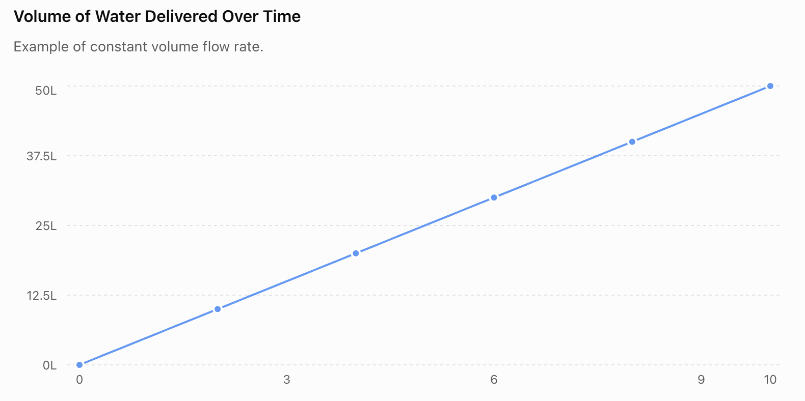
The graph shows:

50 L in 10 s

Therefore:

Q = 50 ÷ 10

Q = 5 L/s

The straight line indicates that the flow rate is constant.

The gradient of a volume-time graph represents the flow rate.

A steeper line means a greater flow rate.


Fluid Flow and Energy

Moving fluids carry energy.

However, some of this useful mechanical energy can be transferred because of:

  • friction
  • turbulence
  • pipe bends
  • valves
  • rough surfaces

Engineers often describe these effects as flow losses or pressure losses.

Reducing unnecessary losses can make a system more energy efficient.

For example:

less resistance → less pumping energy required

This can significantly reduce operating costs in large systems.


Designing an Efficient Pipe System

Suppose an engineer needs to transport water through a building.

A good design should consider:

  • required flow rate
  • available pressure
  • pipe diameter
  • pipe length
  • number of bends
  • valves
  • fluid properties
  • energy use
  • material cost

A very small pipe might be inexpensive but produce excessive resistance.

A very large pipe might reduce resistance but cost much more.

The engineer must choose a practical compromise.


Common Mistakes

Mistake 1: Confusing flow rate and fluid speed

They are related but different.

Speed tells us how fast the fluid moves.

Flow rate tells us how much fluid passes a point per unit time.


Mistake 2: Thinking fluids only flow because of gravity

Gravity can cause fluid flow, especially in rivers and drainage systems.

However, pressure differences can also drive flow.


Mistake 3: Saying narrow pipes always have greater flow rates

Not necessarily.

For a given steady incompressible flow, the fluid moves faster through the narrower section of the same flow path.

But a completely separate narrow pipe supplied by the same pressure difference often has a lower overall flow rate because it provides greater resistance.

These are different situations.


Mistake 4: Thinking laminar flow means the fluid is not moving

Laminar fluid is moving.

Its motion is simply smooth and orderly.


Mistake 5: Thinking turbulent flow means the fluid moves only forward

Turbulent fluid still has an overall direction of flow, but it also contains irregular fluctuations, mixing and eddies.


Mistake 6: Thinking turbulent flow is always undesirable

Turbulence can increase energy losses, but it can also improve:

  • mixing
  • heat transfer
  • chemical reactions

Whether turbulence is useful depends on the application.


Mistake 7: Ignoring viscosity

Fluids do not all flow equally easily.

Honey and water behave very differently because their viscosities are different.


Mistake 8: Assuming fluid speed is the same everywhere across a pipe

Interactions with the pipe wall slow the fluid near the surface.

The velocity can therefore vary across the pipe.


Check Your Understanding

1. Recall

Define fluid flow and give two examples.

2. Flow Rate

A pipe delivers 300 L of water in 60 seconds.

Calculate the flow rate in L/s.

3. Calculate

A hose delivers water at 8 L/min.

How much water will it deliver in 15 minutes?

4. Compare

Describe two differences between:

laminar flow

and

turbulent flow.

5. Explain

Why does honey generally flow more slowly through a narrow tube than water under similar conditions?

6. Fluid Speed

Water moves through a pipe with:

A₁ = 0.06 m²

v₁ = 2 m/s

The pipe narrows to:

A₂ = 0.03 m²

Calculate v₂.

7. Apply

Explain why an old pipe containing mineral deposits might provide a lower flow rate than a clean pipe supplied under similar conditions.

8. Rivers

A river enters a narrower channel while approximately the same volume of water continues to pass each second.

Predict what happens to the average water speed and explain your reasoning.

9. Engineering

An engineer must choose between:

  • a narrow, inexpensive pipe
  • a wider, more expensive pipe

for a long-distance water system.

Explain one advantage and one disadvantage of each choice.

10. Challenge

A student says:

"A narrow pipe always has a greater flow rate because the water moves faster."

Explain why this statement is incorrect.

Your answer should clearly distinguish between fluid speed and volume flow rate.


Key Terms

  • Fluid flow – movement of a liquid or gas
  • Fluid dynamics – study of fluids in motion
  • Flow rate – volume of fluid passing a point per unit time
  • Volume flow rate – another term for volume transported per unit time
  • Fluid speed – rate at which the fluid moves
  • Cross-sectional area – area of a pipe or channel perpendicular to the direction of flow
  • Laminar flow – smooth, orderly fluid motion
  • Turbulent flow – irregular fluid motion involving mixing and eddies
  • Streamline – path representing the direction of smooth fluid flow
  • Viscosity – resistance of a fluid to flowing or deforming
  • Pressure difference – difference in pressure that can drive fluid flow
  • Continuity equation – relationship expressing conservation of fluid flow in a steady system
  • Reynolds number – quantity used to help predict whether flow is laminar or turbulent
  • Eddy – local swirling motion within a fluid

Key Takeaways

  • Fluids can move through pipes, channels, vessels, ducts and natural waterways.
  • Pressure differences and gravity are important causes of fluid flow.
  • Volume flow rate can be calculated using Q = V/t.
  • For flow through an area, Q = Av.
  • For steady flow of an approximately incompressible fluid, A₁v₁ = A₂v₂.
  • When the same steady flow passes through a narrower section, the fluid generally moves faster.
  • Flow rate and fluid speed are not the same thing.
  • Laminar flow is relatively smooth and orderly.
  • Turbulent flow contains irregular motion, mixing and eddies.
  • Flow is affected by pressure difference, pipe diameter, pipe length, viscosity, surface roughness, temperature, bends and obstacles.
  • Fluid-flow principles are important in plumbing, rivers, blood circulation, ventilation, pipelines, irrigation and industrial systems.
  • Engineers must balance flow rate, resistance, energy use, cost and safety when designing fluid systems.

2. Continuity of Flow

Learning outcomes
  • I can explain the principle of continuity in fluid flow.
  • I can describe how cross-sectional area affects flow speed.
  • I can predict how fluid velocity changes in narrow and wide sections.
  • I can apply the continuity equation to simple problems.
  • I can interpret diagrams showing fluid flow through pipes.

What happens to water when a pipe suddenly becomes narrower? Does some of the water disappear? Does it pile up inside the pipe?

For a fluid such as water flowing steadily through a closed pipe, the answer is no. The fluid that enters one section must continue through the next section.

This idea is called the principle of continuity.

It connects three important quantities:

flow rate, cross-sectional area, and fluid velocity.

https://images.openai.com/static-rsc-4/4Fq9k72mXYvt-IMND8l8V88Kxxw8hCPjcTc1M8bU6d_yw88VsFDOK2c446461VSOOzM7wU-RowiNcM0HTcsno2dE0Ldsm0ffsEjpm_oLQdpxO9Kop3pzzNL-5poByZhJgtXR59eiYl516kKGqYu8zt0SMSIueYAGgN1C-mu7Ldu8cb1M_7GnvaKiH2hoHLC1?purpose=fullsize
https://images.openai.com/static-rsc-4/BC5P4YwmulZk9wfLbZncnFnki7N0ccnRyB-jR4htiwowe9F5cNWUArwaTVl0GrvljDU7hgyMkU_DHMHdResEsHakLhZ5tc6gNpYi0sdlcv3LwCY6ZZVsG7XKt6ghdKuoSmu4HHmmZB0dUekYgew8on4fBCZagY48tY7LqojLflIpBhWczd-VggcQdf5m4jcE?purpose=fullsize
https://images.openai.com/static-rsc-4/Yy5_40sQrx4bAkJIn_6j08GX_oIBuP46xPLDGIJcDK9V0fv9CHloISVVudbBcy5hG8QSwZynaz0I8ybvkP0RgmmaHfYzbNsT6gfAxDBF7zi-YHDCpIAzCsUJ48uOdY6LTyGu7ABb0UG7YPmXiCLOM-JUDjQuFmvVwy7PpX8CMy4D5gHoPVRK5VlsyophnUfm?purpose=fullsize
5

What Is Continuity of Flow?

The principle of continuity is based on conservation of mass.

For steady flow:

The mass of fluid entering a section of a system per unit time equals the mass of fluid leaving it per unit time.

For a liquid such as water, which is approximately incompressible, its density stays nearly constant.

Therefore, the same volume of liquid per second must pass through each section of a pipe.

In simple terms:

What flows in must flow out.

If 5 L of water per second enter a pipe, then under steady conditions approximately 5 L/s must continue through each section.


Imagine a Pipe

Consider a pipe with one wide section and one narrow section.

 
       WIDE                     NARROW

  → → → → → → → →             → → → →
 ┌─────────────────┐          ┌───────┐
 │                 │──────────│       │
 │      WATER      │──────────│ WATER │
 │                 │──────────│       │
 └─────────────────┘          └───────┘

   Lower speed                 Higher speed
   Larger area                 Smaller area
 

If water is flowing steadily, the same volume must pass each section every second.

But the narrow section has less space available.

Therefore, the water must move faster through it.

So:

larger area → lower velocity

smaller area → higher velocity

for the same steady volume flow rate.


Cross-Sectional Area

The cross-sectional area of a pipe is the area you would see if you cut straight across the pipe.

https://images.openai.com/static-rsc-4/SQyx3oofV8UIIWbZl82x8V0-s-tHAa0G6eowXHHY8MEYwHWKhmsoL4HGGW9J6PriJNiZsk0NHe_hPGiGcG17c93gSXx1uSE1YwwgkqSlTJaMEJPSf-tnbgPq4DMsmjnV39UhJAdM1llBrUR_ftgkR87nYGJ_Oz_qJ11SaArPg_MVvzXliHlStVdNT1uVRaBI?purpose=fullsize
https://images.openai.com/static-rsc-4/uX1Od8LYKf7DkGu6H9y43fqiPXZTPG2obvnHkrfUlXl546AbHG5hHJXXoc66ifNHzXG-iRf_KvrV4ZvCrKanw9RCqRNIZh2Oxzdd46pYDViimEfFVuAMApAFcY7paGgIhmDtqImfjtPHFD8wYTwjHAwYOgZCiAgAEYB8QpwnVhQIIc4dM_p-s1e5pnCMdtad?purpose=fullsize
https://images.openai.com/static-rsc-4/S0KCmIHPX66a6qlq43GhPQzUpqjF2MgfgMLX7pYUnXBMnUqvm_OWobBatWj8t8TDwNYcDjrntpls9Rn7DwhSZ4Rz3mYIpW3SVZKQDRgFHh_lwtoTd8F_DgLJi8G_PoV6xSiHLM0MehJnYrAwm53jqB6Nb_AF21yM40wuQO80nSD6_geBeTkF3MyLra2RIylP?purpose=fullsize

For a circular pipe:

A = πr²

where:

  • A = cross-sectional area
  • r = radius

Because radius is squared, changing the radius can cause a large change in area.

For example, doubling the radius does not double the area.

It increases the area by a factor of:

2² = 4

This becomes very important in fluid-flow calculations.


Flow Rate

Recall from the previous topic that volume flow rate is:

Q = V/t

where:

  • Q = flow rate
  • V = volume
  • t = time

Flow rate can also be calculated using:

Q = Av

where:

  • A = cross-sectional area
  • v = average fluid velocity

Therefore:

Flow rate = cross-sectional area × fluid velocity

For example, a wide pipe with slow-moving water can have the same flow rate as a narrow pipe containing faster-moving water.


Why Is Q = Av?

Imagine water travelling through a pipe during 1 second.

https://images.openai.com/static-rsc-4/LeEQbcAaMFp2RgIduGmGwEfgpqqkNMNO4OAUqPWozp0laYhcS-cCTvtrrS_L7vWPk1uFyOGi3zgntkR_mJ-SVIMTA1WDfPT03EEK7RpQX0RSQ90GCZ5hANyraz5eRGXjdbRPidT5YLRHlcwqJQttplXPGV2jF_tRwq0Thz6qhnPnikUApwDnypvxlml-LIrC?purpose=fullsize
https://images.openai.com/static-rsc-4/PFMgg9LbvjmPb9zkcGYWC0GCGf8feSI5FradgmSLpyAnM-b9CO_4xgMhme9R_uN6ImlEO69G0w5QOzDB3YQksyE4d_yvZJL4s-12yqAVJHe9b48-lh_Kt3TmPNyoE9TIQ3bkHU1ULPdDzI0EAugYZURtKp3hokrcYxRjhztUn4mOGc0sEO0rfCw4_wFU_4it?purpose=fullsize
https://images.openai.com/static-rsc-4/3TEmX2X5unlA99I_LjGiCLbxGubY9sMzYVbJcjyDUtbvTKBuCag3X-7b28SBhxXPP6xgYmHvEBrDdNKRZ3N50VVjHDVZSSRoj9FgHshi-i1_94Q2oxiYQxLpRUiamE1CeU_LJ1Fb-tcEYUpisbMRLpuksiyNVS4AHvWSN9dRsz4OECqMk6kvJUGDOW8gQ6HH?purpose=fullsize
5

If the water moves a distance d, then the volume that passes a point is approximately:

Volume = Area × distance

or:

V = Ad

But:

velocity = distance ÷ time

so:

d = vt

Substitute into the volume equation:

V = A(vt)

Therefore:

V = Avt

Divide by time:

V/t = Av

Since:

Q = V/t

we obtain:

Q = Av


The Continuity Equation

For steady flow of an incompressible fluid:

Q₁ = Q₂

Since:

Q = Av

we can write:

A₁v₁ = A₂v₂

This is the continuity equation.

where:

  • A₁ = cross-sectional area at position 1
  • v₁ = fluid velocity at position 1
  • A₂ = cross-sectional area at position 2
  • v₂ = fluid velocity at position 2

This equation tells us how fluid velocity changes when the pipe's area changes.


Understanding the Relationship

Suppose:

A₁ > A₂

The second section is narrower.

Because:

A₁v₁ = A₂v₂

the smaller area must be balanced by a larger velocity.

Therefore:

v₂ > v₁

So:

Fluid moves faster through the narrower section.

https://images.openai.com/static-rsc-4/0y7LkMFz8dB_kTv0esgBaauAZevzwA8UCgOJz6q8IlT1iWbzHXEJtst0gTWhTo63O6o7uesV1o8NlnqkZ3T3-dzdZMI5L3MIOmsMz7tPzE0Q3ksmPtRIlkgC7R2a3gziWoiYmFKRqaftFx3WmRGzWV7ZV7ow4hbyeAQQDnh8D08WU_QqUd310ta6V7aWwRmR?purpose=fullsize
https://images.openai.com/static-rsc-4/4Fq9k72mXYvt-IMND8l8V88Kxxw8hCPjcTc1M8bU6d_yw88VsFDOK2c446461VSOOzM7wU-RowiNcM0HTcsno2dE0Ldsm0ffsEjpm_oLQdpxO9Kop3pzzNL-5poByZhJgtXR59eiYl516kKGqYu8zt0SMSIueYAGgN1C-mu7Ldu8cb1M_7GnvaKiH2hoHLC1?purpose=fullsize
https://images.openai.com/static-rsc-4/VBCYX1NSreq2bMDMmM3_5hc6eGT-yJ0kRVx6U1gLVWZ4UC8GoMn8W0jyk70VXPAuWkNCPXwBe3_NyIDs0GJgQcy5AMZ2Xg0x__LzKSsFEoU_SSO-ZI5FR301sCWCP7gxDTDHE0kQ4MmX2clRdotwFn6rnS2rlYlay8iie5DV634nr8PCaoiXbrp4IjmfQApW?purpose=fullsize
5

An Everyday Analogy

Imagine ten students walking through a wide hallway.

They approach a narrow doorway.

If the same number of students must pass a line each second without building up in front of the door, they must move through the narrower space more quickly.

A fluid behaves similarly under steady-flow conditions.

The analogy is not perfect, but it helps illustrate the main idea:

smaller available area → greater required speed

when the flow rate stays constant.


Worked Example 1: Pipe Narrows by Half

Water flows through a pipe.

At Section 1:

A₁ = 0.040 m²

v₁ = 2.0 m/s

The pipe narrows to:

A₂ = 0.020 m²

Calculate the new velocity.

Use:

A₁v₁ = A₂v₂

Substitute:

0.040 × 2.0 = 0.020 × v₂

0.080 = 0.020v₂

Therefore:

v₂ = 4.0 m/s

Answer

The fluid velocity increases from:

2.0 m/s → 4.0 m/s

The area was halved, so the velocity doubled.


A Useful Shortcut

If the cross-sectional area changes by a simple factor, we can often predict the answer without doing a full calculation.

If area becomes:

½ as large → velocity becomes 2 times larger

If area becomes:

⅓ as large → velocity becomes 3 times larger

If area becomes:

2 times larger → velocity becomes ½ as large

If area becomes:

4 times larger → velocity becomes ¼ as large

This is because area and velocity are inversely related when flow rate remains constant.


Area and Velocity Graph

For a constant flow rate:

v = Q/A

Therefore, velocity decreases as cross-sectional area increases.

This is an inverse relationship, not a straight-line relationship.

A very small area requires a relatively high velocity to maintain the same flow rate.


Worked Example 2: Pipe Gets Wider

Water moves through a narrow pipe at:

6.0 m/s

The cross-sectional area is:

0.010 m²

The pipe widens to:

0.030 m²

Calculate the new velocity.

Use:

A₁v₁ = A₂v₂

Substitute:

0.010 × 6.0 = 0.030 × v₂

0.060 = 0.030v₂

Therefore:

v₂ = 2.0 m/s

Answer

The water slows from:

6.0 m/s → 2.0 m/s

because the pipe becomes three times wider in cross-sectional area.


Interpreting Flow Diagrams

You may be given a diagram rather than numerical data.

For example:

 
Section A             Section B              Section C

██████████              ████                ████████████
→  →  →  →              →→→→→→              →  →  →
██████████              ████                ████████████

   Wide                 Narrow                 Widest
 

For the same steady flow:

Section B has the smallest area → greatest velocity

Section C has the largest area → lowest velocity

So:

vB > vA > vC

Being able to make this comparison without calculations is an important fluid-flow skill.


Worked Example 3: Three Sections

A pipe has three sections:

  • Section A: 0.060 m²
  • Section B: 0.020 m²
  • Section C: 0.040 m²

Rank the fluid velocities from greatest to smallest.

For constant flow:

smaller area → greater velocity

The smallest area is B.

Then C.

The largest area is A.

Therefore:

vB > vC > vA


Using Diameter Instead of Area

Some questions give the diameter of a pipe rather than its cross-sectional area.

Be careful.

The continuity equation uses area, not diameter.

For a circular pipe:

A = πr²

and:

r = d/2

Therefore:

A = π(d/2)²

or:

A = πd²/4

This means area is proportional to:

diameter²


Why Diameter Can Be Tricky

Suppose the diameter of a pipe decreases by half.

A common mistake is to assume the area also decreases by half.

It does not.

Because:

A ∝ d²

if:

d₂ = ½d₁

then:

A₂ = (½)²A₁

so:

A₂ = ¼A₁

The cross-sectional area becomes four times smaller.

Therefore, for constant flow:

v₂ = 4v₁

The fluid moves four times faster.


Worked Example 4: Changing Diameter

Water flows at:

2 m/s

through a pipe with diameter:

8 cm

The pipe narrows to:

4 cm

Calculate the new speed.

Because diameter is halved:

Area becomes ¼ as large.

Therefore, to maintain the same flow rate:

velocity becomes 4 times larger.

So:

v₂ = 4 × 2

v₂ = 8 m/s

Answer

The water moves at:

8 m/s

in the narrower section.


Solving It Using Areas

We can verify the previous answer mathematically.

Section 1

Diameter:

8 cm

Radius:

4 cm

Area:

A₁ = π(4)²

A₁ = 16π cm²

Section 2

Diameter:

4 cm

Radius:

2 cm

Area:

A₂ = π(2)²

A₂ = 4π cm²

Now:

A₁v₁ = A₂v₂

16π × 2 = 4π × v₂

Cancel π:

32 = 4v₂

Therefore:

v₂ = 8 m/s

Same answer.


A Garden Hose

The continuity principle helps explain what happens at a hose nozzle.

https://images.openai.com/static-rsc-4/yHBg0DYKi1QfSzPc3_RwRt2J-GX0r79G9zF0KXdgVTOW5uUa9cftsFMLBgs999UGK5pI058YDVUvZT78sbU9UAc3cL5N6cPgWE_KwW_BjZNNPntwHZ0rIwDogv6sAXsVrkccigMDoznO9uhohzK0WxF3bBdqV_b2-9Mqxy-vzQc0pOMmwDVVJ4oH8_XvXkXg?purpose=fullsize
https://images.openai.com/static-rsc-4/99wa2qhdOIZrHAgF8WK2f5FEF9IKIvXO2vXzWGJZxw8MF1b7oaPh0_uUZtSUyBG0hDYdmKLutsf_kkwV7U0Xa6nLnkW9-4xB6q_8r8MsoyDLEQcj_ZzhrRgDS963UAZqDMTS52LjpAM5YSVF1TznMQOwAvqDxDjEsJJpORQ26gwnBMuHDc2jXgICp37wdNwD?purpose=fullsize
https://images.openai.com/static-rsc-4/Yy5_40sQrx4bAkJIn_6j08GX_oIBuP46xPLDGIJcDK9V0fv9CHloISVVudbBcy5hG8QSwZynaz0I8ybvkP0RgmmaHfYzbNsT6gfAxDBF7zi-YHDCpIAzCsUJ48uOdY6LTyGu7ABb0UG7YPmXiCLOM-JUDjQuFmvVwy7PpX8CMy4D5gHoPVRK5VlsyophnUfm?purpose=fullsize
5

The hose has a relatively large cross-sectional area.

The nozzle provides a smaller exit area.

For a given flow rate, water passing through the smaller opening has a greater exit velocity.

This creates a faster, narrower jet.

However, real hose systems also experience pressure losses, and partially closing a nozzle may change the overall flow rate. The continuity equation describes how area and velocity relate for the flow rate that actually occurs.


Nozzles

Nozzles deliberately change cross-sectional area to control fluid velocity.

Examples include:

  • garden hoses
  • fire hoses
  • spray bottles
  • irrigation systems
  • industrial jets
https://images.openai.com/static-rsc-4/QDU9DhowMteR7h7lWBXnAtZK0Kmf-3DxPmOX66h5S6asDQRcT-8TOWZHl613SOdL4sDLU9QIhedJ8LBjySSyxvDJL7_darUjCnyuk3YnsIDh_C5lcLDyNIksbDb1vB75-jRlbTHWPaFBbSn6zZZpCj6z-Om_sZGTT6vOXKGX-L7B5MU2mnGQkWT6lIIxJCQE?purpose=fullsize
https://images.openai.com/static-rsc-4/NOFiKqJx2XJ00iRGd7_5D7pV_53aA0VjlgMc2PUAGU_JOFjktmvvXQZmOaqfBkQayCSGl7bH4uiyTIETshwWy6r01XXXV2ENOs8hG5xFDUlnEDfFGENiMYec7BRr2AMUh66Ky5hkYCPI7TpB4Ju-PmNYPGiSPz6A0G3qtYrlSI202I6ShvI6YNeqEIp-BGs9?purpose=fullsize
https://images.openai.com/static-rsc-4/Z_fwxIe_w7Yf_0MpJC_JRwj8iLf_gBEGYowQ4UXDBA8DpMor502qaXED94pS1UOFqDJYEYdJNLvaYXqguk5pWsKV6t7BinbmWsT34UuyzfgvuNiX4ChGup54tXREBdLlgkvgUOhV1P4zjBMWsQggKU-iXSI9MoHidZNgYBDMNrtU4S9gTX5_d-f_GcaFoeK8?purpose=fullsize
5

A narrower outlet can produce a faster jet for a given flow rate.

This can allow the fluid to travel farther or strike a target with greater speed.


Rivers and Continuity

The principle of continuity can also help us understand rivers.

Suppose approximately the same volume of water passes through different parts of a river each second.

If the river channel becomes narrower:

cross-sectional area decreases

so:

average water velocity tends to increase

https://images.openai.com/static-rsc-4/j2dv_1NTEbx30Ltjc6q9GLtEDUxXhRfV19IQjUbDTCBeI1fkoRLT-Ve5NSiINGwCKDDfDBqkt3_TZ5T3XkErUebBLrkDnwJIwLIY-AE2GKzZmlo0yhCxtiVRpAvNimeRypfmNGDYUEgC4cFPcMJQrlsHiNQdWt4hrQW9pSvtHiJyP6Ob8g7uVsazwC_4SLa9?purpose=fullsize
https://images.openai.com/static-rsc-4/EucrKjNoce4GEdvhhUWi9RM_L16gso_J1xTnhslNM2OVy1NgkYwtQXdQnB86b3yfjBygIM7RWH_9UNVRNAP2a1jhiblWHbJ2MGtt81DhW20m1ED-2RzFeMz3AFnyB0nNirQBz1ccAO0DhLXwPL7zmYCTW4_U0ek0Z8XJ79Ycxn3ZE8QjWeHxNlOOJTvrQ3Rb?purpose=fullsize
https://images.openai.com/static-rsc-4/BsCY4Es0WqEHTHkuMKgIH8HztOLAnBXK-9J7lKWelI1djmKEn50OiQgqWq4VFfEf0V7divwrk44daPIRSWgKSrzEX1oW3lmTAZ7gzJc-8ZxFDMj8fInoSmWerhL9pFIV0n3XQw4SYLBPB2tOnkTGwpqkly3AM4BbvK-kprR7Wbu_tK-2N33NxBS-nzUTyMXR?purpose=fullsize

However, river cross-sectional area depends on both:

  • width
  • depth

So a narrower river does not automatically mean a smaller cross-sectional area if it also becomes much deeper.

Real rivers also gain and lose water, so the flow rate may not always remain constant.


Blood Flow

The continuity principle also applies to blood flowing through the circulatory system.

https://images.openai.com/static-rsc-4/IEDsc3bHxWJu2TpcUD7CE7s9sT7u1pg7sBE-juA-vRjg-S2ugMBrauDQMPQFIv3gnW8_rlMk8ZSjvzeSebauKyVgb2oV7mP7rzOdqg8A_-4tGfarKg_U0LW1Dzy2tCVp8-HQAI9PrG0EAG6nP4zi8s81hZdkU18DHUal-trrexQdD9d0F_jXnb6rn-RuZPBp?purpose=fullsize
https://images.openai.com/static-rsc-4/4Fq9k72mXYvt-IMND8l8V88Kxxw8hCPjcTc1M8bU6d_yw88VsFDOK2c446461VSOOzM7wU-RowiNcM0HTcsno2dE0Ldsm0ffsEjpm_oLQdpxO9Kop3pzzNL-5poByZhJgtXR59eiYl516kKGqYu8zt0SMSIueYAGgN1C-mu7Ldu8cb1M_7GnvaKiH2hoHLC1?purpose=fullsize
https://images.openai.com/static-rsc-4/8Ak0UCHg1fWYvhllmprw_-82LGe92tsmceVhaQwVSKNqKUIlUhwRZt_0_K0WF_11gM-ME6wzaIe-WH_GoLNE9eQoVjmLAql86lt3PlmOnxXqU55ngn246mSqbaXTzIAlsRzx-1_xq4goVyCjO-DaJ7-TPYnR7WZYGhZYtA83DhhDktxLbIxCCpyoZHyqLrfP?purpose=fullsize
5

If the same volume flow rate passes through a locally narrowed section of a blood vessel, the average blood velocity through that section increases.

This is an application of:

Q = Av

However, the human circulatory system is complex because vessels branch, stretch, pulse and change diameter.


One Vessel vs Many Vessels

There is an important distinction when discussing blood vessels.

A single capillary is extremely narrow.

But the body contains an enormous number of capillaries arranged in parallel.

The total cross-sectional area of all the capillaries together is very large.

Therefore, average blood velocity through the capillary network is relatively low.

This slower movement helps provide time for exchange of:

  • oxygen
  • carbon dioxide
  • nutrients
  • wastes

between blood and tissues.


Ventilation Systems

The continuity equation is also important in ventilation.

If air moves through a duct that narrows, its average velocity generally increases for the same volume flow rate.

https://images.openai.com/static-rsc-4/ZQZbEtVPkbj61Ao88mln9hSyfRMjxNsY516K27T2a-hH56Us3xHB3_KrM4EjSsSb4ECgbM6HIBBoXNWWQulIsYLgBMklYgoIW7S9HBRkUqV_AIL82AWPhdGGq14cbnen1_OM9_M8vf9rCujGXW_RjjVNp43aDirEkFmSQZ2DIeT1aV6_CdlhKX5kTtmLUTTn?purpose=fullsize
https://images.openai.com/static-rsc-4/wU3Dro-JrQhgaJhYQq5cHg9hQsCGto7S0JQEpjnBymajL1_R_icVbFKhHR7USD31HpTRMAcf6qGI69LqQ17YVL260dQDAY-HiPjaYp6np0idPTB6JvOhtHT2B-MEOXw5gSiNLc6d2g2kMgOyhYsD7DUIOJb0RGLkxtlOWt4HGeyiG82-intAjp3OO5H21mBm?purpose=fullsize
https://images.openai.com/static-rsc-4/GmXc9vHAeMrNB7KIUahtQLGp6K7DeZAlyqeyOHew3os334XcQr1gb45Pnot_e8Eg-8rUnSYrP29yDzevZtnH9YZEEgVbIlbHJQIPEQeKUIdtTlYJWWwRR2LkA3XP0aNhBjO3PXbzuAi__yLV35gXo57yE7qoGPcYLVi7vwAaXMwy63FuL5st80uMAdEPrqRj?purpose=fullsize
5

Engineers use these relationships when designing:

  • air-conditioning systems
  • ventilation ducts
  • exhaust systems
  • air intakes
  • industrial ventilation

Controlling air speed can help manage:

  • noise
  • comfort
  • energy use
  • distribution of air

Fire Hoses

Firefighters need to deliver water over significant distances.

A nozzle can reduce the outlet area and produce a high-speed stream.

https://images.openai.com/static-rsc-4/q-K2lUH6a4LgTnz7YS-KwgcXctt6on4oiQAZIEvdTR83ZSnuadViC7mnW4VqCBia-aS-kJoev8WVymvSYxh3EnpPBIHxJQtaiJAKYBivWbZNcYvt4RL1qfhmlqOvkHRcHiMyLjVB1uMMWWrTqdLnWPCt26qQrobdVumnUghkEbVVBvT4v95iMVH3X3-nfurf?purpose=fullsize
https://images.openai.com/static-rsc-4/6cgTs8-9peyBgqyCs-cvmZoUH3mOU74vwuKdqocy-LFQKkriUZuE36tDCZhGTfwZTHwT5qqY5hvapL8W-Kmgc3s38tpaayzYpfDvOzfOGaP24v7lVdpM3YnqfO_P0u35aBAOUCz72WE3hgR_rHvGTOT3LQnz2ffYCewiYuK7XiQP6BtV-vKA6VEfdvO3LmV6?purpose=fullsize
https://images.openai.com/static-rsc-4/RC_FOMaRfp7wYnMPnJZMpfjBHf6tNfWNxab3E0C6JvguTNKlxmVJhWKk5spV3nglk2r3LZh-cKWCLKK37rNyb47kMxu6rwWanoh4VHg8eo_HszE6TKXjkrYSWzvdZOOV90zooSjZ1yyIEa2H3qfIPH5_OV7XMfh-A8GbMcWKpMz-yOZmRT8JXzK3na0uvYlY?purpose=fullsize
4

The continuity relationship helps explain why the fluid velocity at the nozzle can be greater than in the wider hose.

However, pumps must provide sufficient pressure and flow because real hoses also experience resistance and energy losses.


Irrigation Systems

Agricultural irrigation systems use carefully designed pipes and nozzles.

The size of an outlet affects the velocity and amount of water delivered.

https://images.openai.com/static-rsc-4/tc1M1oI48BUoPBzhN01mg4hoNWXq8qyS4n2psAyUzmLuk3DO4DsKIZDrlQ9q4ueuhb5ijFcQQR2Wz3uXGvExWRvbgzQRVimLtEFLt95b6Kx2kv4im6GarJ_7i-Y5iZ5NE1TptYv5jaMMMMOpznOpsbSW4y7iUJ7lcPIBUt05KqpsbYR-_bUcM6_5tMzHlllL?purpose=fullsize
https://images.openai.com/static-rsc-4/tJuPUiVXIZPxEWRjOfbrOzLAfXGIIed6vVY2s53Ko2qhnIlXd3LcVw9kQssdKSiNOF-Gpw6t4i29V7DeMQtOspjNkMI-b4b3Y5MG6xWKJCfX_36OnV9Uowx0bjHmBzvCGrhRybQkYe0OUhZ0PPwbDzRc5YmpYFPZkDMQzKdrdc4u_z6CvUeqogwN_afeA3JT?purpose=fullsize
https://images.openai.com/static-rsc-4/NAJu6aLRojCvE-xxgGNbG3ZFGvpWqEBdKciSIazSs3uB7W0uDshk3tFV0wmhKRAZUm3LoHnI1qK33uxOUE0WwXMUFRHIPSv9gxoJObvqRjYPSfKIkaejd11nQnAEkJeNNYHu9i9OnpZjZYhIkFXB5hrBp-W7jMYeLk49m80X0Szpzjg0ROq5iyBn5Kz1lLQG?purpose=fullsize
7

Engineers must consider both:

flow rate

and:

exit velocity

A system may need to provide enough water while also producing a spray that reaches the required area.


Mass Continuity

So far, we have focused on liquids such as water.

For an incompressible fluid:

A₁v₁ = A₂v₂

But the more general idea is conservation of mass.

The mass flow rate is:

mass flow rate = ρAv

For steady flow:

ρ₁A₁v₁ = ρ₂A₂v₂

For an incompressible liquid:

ρ₁ ≈ ρ₂

so density cancels:

A₁v₁ = A₂v₂

This explains why the simple continuity equation works well for many liquid-flow problems.


What About Gases?

Gases can be compressed much more easily than liquids.

Therefore, their density can change significantly as they flow.

For simple situations with small density changes, we may still use:

A₁v₁ ≈ A₂v₂

as an approximation.

But when gas density changes significantly, the more general mass-flow equation is needed:

ρ₁A₁v₁ = ρ₂A₂v₂

This is important in advanced applications involving:

  • aircraft engines
  • compressors
  • turbines
  • high-speed gas flow

Continuity Does Not Mean Pressure Stays Constant

A very important point:

Continuity tells us about flow rate, area and velocity.

It does not say that pressure remains constant.

As a fluid changes speed, its pressure may also change.

https://images.openai.com/static-rsc-4/ZguFL5PmLOI0d-FTimPWKfXarvmQyDlToHvWMjeQ5jay1ttCYobm85k_xICwTat2Qm76PuIloiJnpNYx7N8ZXXOjEfdxY4V2HEzHYx0el8mVX-KFacbCPXJdnTr2dd8LirBlPFCcHd_JikrUkUv94ewPvC3eSY-UMT8oKx09blOOBc-_iwkSb1EDB54JHmlE?purpose=fullsize
https://images.openai.com/static-rsc-4/scyDcJKM28GiOlegC4rAXA12t2C3va6vyhfkKQyQdiUDFrBLvQHScaiUbu5xmiBKl842m7GkgCMfdHWvjX0qtTD-NjueuYqQTClLu5Jz35W3vcYEBJjxYxVIm4Li5qHZiPxTsO1ibfegxP4CpaBuZKOnD-lvGCJy4ajyzjQGqL0sHVFZpvNR1_Q7djQhy__g?purpose=fullsize
https://images.openai.com/static-rsc-4/aEzEavK2OU29So5oNXciEJ6g90jhNG0N9ycKenv7dgJsqCsjWuQpaNbEHV0VSSuov6b8K4KWRS8xyWE4dSAC7UnfuZAnU3MKu9UYWsog7fQXmtGYdfGfDz6mLbqnMQpSfXQkn-ZOf1uV3DKjDyxdbkVEAdqWxG7o0PUMZ_g08n-Hc6XWvZwhuKgBN9KmFtdY?purpose=fullsize
5

The relationship between fluid speed and pressure leads us toward another important idea in fluid dynamics: Bernoulli's Principle.

For now, remember:

continuity → conservation of flow/mass

while:

pressure changes require additional fluid-dynamics ideas.


A Step-by-Step Problem-Solving Method

For continuity problems, use this method.

Step 1: Identify the two sections

Label them:

Section 1

and:

Section 2

Step 2: Write down the known values

Identify:

  • A₁
  • v₁
  • A₂
  • v₂

Step 3: Write the continuity equation

A₁v₁ = A₂v₂

Step 4: Rearrange

For example, to find v₂:

v₂ = A₁v₁/A₂

Step 5: Substitute values

Include units.

Step 6: Check whether the answer makes sense

Ask:

Did the pipe become narrower?

Then velocity should increase.

Did the pipe become wider?

Then velocity should decrease.

This simple check can catch many calculation errors.


Worked Example 5: Finding Area

Water moves through a pipe at:

v₁ = 3 m/s

with:

A₁ = 0.040 m²

The water then slows to:

v₂ = 2 m/s

Find the new cross-sectional area.

Use:

A₁v₁ = A₂v₂

Substitute:

0.040 × 3 = A₂ × 2

0.120 = 2A₂

Therefore:

A₂ = 0.060 m²

Answer

The new area is:

0.060 m²

This makes sense because the water slowed down, so the pipe must have become wider.


Worked Example 6: Finding the Flow Rate

Water moves through a pipe with:

A = 0.025 m²

and:

v = 4 m/s

Calculate the volume flow rate.

Use:

Q = Av

Q = 0.025 × 4

Q = 0.100 m³/s

Answer

The flow rate is:

0.100 m³/s

Since:

1 m³ = 1000 L

this is also:

100 L/s


Worked Example 7: Challenge Problem

A pipe has a diameter of 12 cm.

Water moves through it at 1.5 m/s.

The pipe narrows to a diameter of 6 cm.

Find the new velocity.

The diameter is halved.

Therefore, area becomes:

(½)² = ¼

of its original value.

To keep:

Av = constant

velocity must become four times larger.

Therefore:

v₂ = 4 × 1.5

v₂ = 6.0 m/s

Answer

The water velocity in the narrow section is:

6.0 m/s


Interpreting Arrow Diagrams

Fluid-flow diagrams often use arrows to represent velocity.

Longer arrows may indicate greater speed.

For example:

 
WIDE                  NARROW                  WIDE

→  →  →             →→→→→→→→             →  →  →
██████████            █████                ██████████
██████████            █████                ██████████
 

You should be able to identify that:

  • velocity increases entering the narrow section
  • velocity decreases when the pipe widens again
  • the steady volume flow rate remains the same through each section

This type of reasoning is often more important than calculation.


Common Mistakes

Mistake 1: Saying narrow pipes always have greater flow rates

For one steady incompressible flow:

flow rate stays the same

while:

velocity changes

The narrow section has greater velocity, not necessarily a greater volume flow rate.


Mistake 2: Confusing area and diameter

The continuity equation uses cross-sectional area.

If diameter halves, area becomes one-quarter, not one-half.

Remember:

A ∝ d²


Mistake 3: Saying water is "squeezed" into a smaller volume

Liquid water is approximately incompressible under ordinary conditions.

It does not need to become significantly compressed.

Instead, it moves faster through the smaller area.


Mistake 4: Assuming velocity increases when a pipe widens

It is the opposite for the same steady flow:

larger area → lower velocity


Mistake 5: Thinking continuity means velocity is constant

Continuity means the appropriate flow quantity is conserved.

Velocity can change when cross-sectional area changes.


Mistake 6: Assuming pressure is constant

The continuity equation does not tell us that pressure remains constant.

Pressure can change as fluid velocity and height change.


Mistake 7: Forgetting that real systems have resistance

The simple continuity equation describes conservation of mass.

Real pipes also have:

  • friction
  • turbulence
  • bends
  • valves
  • pumps

These can affect the actual flow rate and pressure.


Mistake 8: Applying the simple equation to strongly compressed gases

The equation:

A₁v₁ = A₂v₂

assumes approximately constant density.

For significantly compressible gas flow, density must also be included.


Check Your Understanding

1. Recall

State the principle of continuity in your own words.

2. Predict

Water flows from a wide section of pipe into a narrower section.

What happens to its average velocity?

Explain why.

3. Compare

Section A has an area of:

0.050 m²

Section B has an area of:

0.010 m²

If the same steady water flow passes through both sections, which has the greater velocity?

4. Calculate

Water flows through:

A₁ = 0.040 m²

at:

v₁ = 3 m/s

The pipe narrows to:

A₂ = 0.020 m²

Calculate v₂.

5. Calculate

Water flows at:

8 m/s

through a pipe with area:

0.015 m²

The pipe widens to:

0.060 m²

Calculate the new velocity.

6. Flow Rate

Water moves through a pipe with:

A = 0.030 m²

v = 5 m/s

Calculate the volume flow rate.

7. Diameter

The diameter of a pipe decreases from:

10 cm → 5 cm

By what factor does its cross-sectional area change?

If the flow rate remains constant, by what factor does the velocity change?

8. Diagram

A pipe has three sections:

A → B → C

with:

AA > AC > AB

Rank the fluid velocities from greatest to smallest.

9. Apply

Explain how the continuity principle helps explain the high-speed stream leaving a fire-hose nozzle.

10. Challenge

A student says:

"When a pipe gets narrower, less water can fit through it, so the flow rate must decrease."

Explain why this is not necessarily true for steady flow through different sections of the same pipe.

Use the terms:

cross-sectional area, velocity, and flow rate.


Key Terms

  • Continuity – principle based on conservation of mass during fluid flow
  • Continuity equation – equation relating fluid velocity and cross-sectional area
  • Cross-sectional area – area of a pipe perpendicular to the direction of flow
  • Volume flow rate – volume of fluid passing a point per unit time
  • Mass flow rate – mass of fluid passing a point per unit time
  • Velocity – speed of fluid in a particular direction
  • Incompressible fluid – fluid whose density changes very little under ordinary conditions
  • Steady flow – flow in which conditions at a particular location do not change significantly with time
  • Conservation of mass – principle that mass cannot simply appear or disappear
  • Nozzle – device designed to control the direction or velocity of a flowing fluid

Key Takeaways

  • The principle of continuity is based on conservation of mass.
  • For steady flow, the amount of fluid entering a system must equal the amount leaving.
  • For an approximately incompressible fluid, the volume flow rate remains constant through different sections of the same unbranched pipe.
  • Volume flow rate is given by Q = Av.
  • The continuity equation is A₁v₁ = A₂v₂.
  • A smaller cross-sectional area produces greater fluid velocity for the same steady flow rate.
  • A larger cross-sectional area produces lower fluid velocity.
  • Area and velocity are inversely related when flow rate is constant.
  • Pipe diameter and area are not the same; area is proportional to diameter squared.
  • Continuity helps explain fluid behaviour in nozzles, hoses, rivers, blood vessels, ventilation systems and irrigation systems.
  • Continuity does not mean pressure remains constant.
  • For significantly compressible fluids, such as gases under large pressure changes, density must also be included using ρ₁A₁v₁ = ρ₂A₂v₂.

3. Bernoulli's Principle

Learning outcomes
  • I can state Bernoulli's Principle.
  • I can explain the relationship between pressure and fluid speed.
  • I can describe how energy is conserved in flowing fluids.
  • I can apply Bernoulli's Principle to explain observed phenomena.
  • I can solve simple problems involving pressure and fluid flow.

Why does pressure change when a fluid speeds up? Why can a narrow section of pipe have faster-moving fluid but lower static pressure? How can moving air help produce forces on wings, sails, and roofs?

These questions involve one of the most important ideas in fluid dynamics: Bernoulli's Principle.

In a simplified steady-flow situation:

Where a fluid moves faster, its static pressure tends to be lower, provided other relevant conditions such as height are accounted for.

Bernoulli's Principle is fundamentally an application of conservation of energy to a moving fluid.

https://images.openai.com/static-rsc-4/suKNPlZJ4PPaqrmXOwXsl0jxPRnH0AMFfZBCukThEh43w1Bw0Y3aUyn7yIHSaakJcB9CTkWvnng8x9nAfRmx7zXN5FAklDFUceSc65phGI2bMlsQmCQnNeb113PnWYcfiiSIabcyn7aZeCpjCQw3MN2DG7fXD3YrERiAL6ILxTPcHgmcHpg2j7tUEtEp1HeY?purpose=fullsize
https://images.openai.com/static-rsc-4/VBCYX1NSreq2bMDMmM3_5hc6eGT-yJ0kRVx6U1gLVWZ4UC8GoMn8W0jyk70VXPAuWkNCPXwBe3_NyIDs0GJgQcy5AMZ2Xg0x__LzKSsFEoU_SSO-ZI5FR301sCWCP7gxDTDHE0kQ4MmX2clRdotwFn6rnS2rlYlay8iie5DV634nr8PCaoiXbrp4IjmfQApW?purpose=fullsize
https://images.openai.com/static-rsc-4/aEzEavK2OU29So5oNXciEJ6g90jhNG0N9ycKenv7dgJsqCsjWuQpaNbEHV0VSSuov6b8K4KWRS8xyWE4dSAC7UnfuZAnU3MKu9UYWsog7fQXmtGYdfGfDz6mLbqnMQpSfXQkn-ZOf1uV3DKjDyxdbkVEAdqWxG7o0PUMZ_g08n-Hc6XWvZwhuKgBN9KmFtdY?purpose=fullsize
6

From Continuity to Bernoulli

In the previous topic, we learned the continuity equation:

A₁v₁ = A₂v₂

For steady flow of an approximately incompressible fluid:

narrower section → greater fluid speed

But this raises another question:

What happens to the pressure when the fluid speeds up?

Bernoulli's equation helps answer this.

For a horizontal pipe under idealized conditions:

greater speed ↔ lower static pressure

and:

lower speed ↔ higher static pressure

This connection between speed and pressure is one of the central ideas of Bernoulli's Principle.


Bernoulli's Principle

A useful statement of Bernoulli's Principle is:

For steady flow of an ideal fluid along a streamline, the total mechanical energy per unit volume remains constant.

That energy can appear in three main forms:

  • pressure energy
  • kinetic energy
  • gravitational potential energy

If one form increases, another must decrease if no external energy is added and losses are negligible.


Bernoulli's Equation

The mathematical form is:

P + ½ρv² + ρgh = constant

Between two positions:

P₁ + ½ρv₁² + ρgh₁ = P₂ + ½ρv₂² + ρgh₂

where:

  • P = static pressure (Pa)
  • ρ = fluid density (kg/m³)
  • v = fluid speed (m/s)
  • g = gravitational field strength (m/s² or N/kg)
  • h = height (m)

Each term has units of:

Pa = J/m³

So each term represents energy per unit volume.


The Three Energy Terms

Pressure Term

P

This represents energy associated with the fluid's static pressure.

Kinetic Term

½ρv²

This represents kinetic energy per unit volume due to fluid motion.

Faster fluid has a larger kinetic term.

Gravitational Term

ρgh

This represents gravitational potential energy per unit volume.

Fluid at greater height has a larger gravitational term.

So Bernoulli's equation can be summarized as:

pressure energy + kinetic energy + gravitational potential energy = constant

under the ideal conditions assumed.


A Horizontal Pipe

Suppose a pipe remains at the same height.

Then:

h₁ = h₂

so the gravitational terms cancel.

Bernoulli's equation becomes:

P₁ + ½ρv₁² = P₂ + ½ρv₂²

Now the relationship becomes easier to see.

If:

v₂ > v₁

then:

½ρv₂² > ½ρv₁²

So the kinetic term has increased.

For the total to remain constant:

P₂ < P₁

Therefore:

In this ideal horizontal-flow case, faster-moving fluid has lower static pressure.

https://images.openai.com/static-rsc-4/m7Hr-KftcekWb0UlLwyjLu8klHkMtBLy0KAZm7BFkToEM-fRqjPC2VnAXJGbCwGAz2zGSfsEK7uYl3rTIufUtxODmWyh28F2cdGJY5wxEtbOEOl0IZn39DeCDTpJnLbuEvVNOBelInk4osHNmH2RisHPamRKDcJ30cGSSsHbfZxvMLcUBtgdKyNGrqo_fcOJ?purpose=fullsize
https://images.openai.com/static-rsc-4/V5oDac722S7BYbVG28xZ-jKQuyzmxs7Us4bD-_EIHVIRF_veoxkiCJRlRXKWPBDWaBVInl48JmUNdwfKx7JaupjsiMJOhGjN5fuGWKkhHscvxqfT9xKXgudGiTDwKN_QdJLg2Gy0l5fptWWfR9bhkzo5jJZFiu8nrI71cg_mEbvBkOVB363miijs-BJ7NKSV?purpose=fullsize
https://images.openai.com/static-rsc-4/uprfpXheIeLcfQsME_3h_6yo-vjJg-48sM1-yVD2J7X_NmFhzKn0DRiuODHKCbs9EywWvIdxWGTuIG84JN9BrY7Gj0EoEMsjiHxc9iBwdnGhGJYd-TaM8J9uP_Yx6la5nwoMOLn0kNfH7krY3Fpt8vd_tVNWEDTnTYVb-JjpPTJvCL71-UAUNQsPAy1Kyvr-?purpose=fullsize
6

Continuity + Bernoulli

These two principles work together.

Continuity tells us:

narrower pipe → greater speed

for the same steady incompressible flow rate.

Bernoulli tells us:

In an ideal horizontal system:

greater speed → lower static pressure

Therefore:

wide section → slower fluid → higher static pressure

narrow section → faster fluid → lower static pressure

 
       WIDE                 NARROW                WIDE

   slower flow            faster flow          slower flow
   higher static P        lower static P        higher static P

 ┌──────────────┐        ┌───────┐        ┌──────────────┐
 │ →   →   →    │────────│→→→→→→→│────────│ →   →   →    │
 └──────────────┘        └───────┘        └──────────────┘
 

This combination is extremely useful in fluid dynamics.


The Venturi Effect

A tube that narrows and then widens again can demonstrate Bernoulli's Principle.

This is often called a Venturi tube.

https://images.openai.com/static-rsc-4/V4Tp4HCNG31FnBM-_TL0qG14lsGxOD1UYcVyxCXAyFsosiD9uQMBtfjS1El3iT-mnXSMVzVD5uDacTp3pLShDkBn6UT_C9S43v7JCcRcXTOWscqEvAmizZsZZMZ833iY0dsNOKYEQcSbS2Uf_CV6UOx46PG7DV3fZWTa1BxeCTJCe32Vq_r3EqD7IKojMkCC?purpose=fullsize
https://images.openai.com/static-rsc-4/VBCYX1NSreq2bMDMmM3_5hc6eGT-yJ0kRVx6U1gLVWZ4UC8GoMn8W0jyk70VXPAuWkNCPXwBe3_NyIDs0GJgQcy5AMZ2Xg0x__LzKSsFEoU_SSO-ZI5FR301sCWCP7gxDTDHE0kQ4MmX2clRdotwFn6rnS2rlYlay8iie5DV634nr8PCaoiXbrp4IjmfQApW?purpose=fullsize
https://images.openai.com/static-rsc-4/dXCTpQmMIxdd6XprqqkTWBk7g53ThZC71PdJEmk4RuACb0TUE5AvGedmAjLpLTzvMg5Va34g3lQWyuEYcbLjQjWcyWbrS63JqG5VhvRhTsZSKVsEqwfliOt3i8q9TNkVcybMbZ1POvNUChGhdfBh8LHjRxPEhb7nLn96lGpUL-DCtylsAcjpiCYbUoQvoUhp?purpose=fullsize
5

At the narrow region, called the throat:

  • cross-sectional area decreases
  • fluid velocity increases
  • static pressure decreases

This pressure difference can be measured.

Venturi devices can therefore be used to determine fluid flow rate.


Why Doesn't the Narrow Section Have Higher Pressure?

This is a common source of confusion.

It is tempting to think:

"The fluid is squeezed into a smaller space, so its pressure must increase."

But in a flowing system, the fluid must accelerate as it enters the narrow section.

Energy is required to increase its kinetic energy.

Under ideal horizontal conditions, that energy comes partly from the pressure term.

Therefore:

pressure energy decreases → kinetic energy increases

So the narrow section can have lower static pressure, not higher static pressure.


Pressure and Speed

Consider an ideal horizontal flow.

If fluid speed increases:

kinetic energy per unit volume increases

Since:

P + ½ρv² = constant

the static pressure must decrease.

If fluid speed decreases:

kinetic energy per unit volume decreases

and static pressure can increase.

This is an example of energy transformation rather than energy disappearing.


Worked Example 1: Pressure Change

Water flows through a horizontal pipe.

At Point 1:

v₁ = 2 m/s

P₁ = 120 000 Pa

At Point 2:

v₂ = 6 m/s

Use:

ρ = 1000 kg/m³

Find P₂.

For a horizontal pipe:

P₁ + ½ρv₁² = P₂ + ½ρv₂²

Substitute:

120 000 + ½(1000)(2²) = P₂ + ½(1000)(6²)

Calculate the kinetic terms:

½(1000)(4) = 2000 Pa

½(1000)(36) = 18 000 Pa

Therefore:

120 000 + 2000 = P₂ + 18 000

122 000 = P₂ + 18 000

So:

P₂ = 104 000 Pa

Answer

P₂ = 104 000 Pa

The fluid moves faster at Point 2, so its static pressure is lower.


Checking the Answer

Before accepting a calculation, always ask:

Does the answer make physical sense?

The water sped up:

2 m/s → 6 m/s

Therefore, in the ideal horizontal case, static pressure should decrease.

Our answer shows:

120 000 Pa → 104 000 Pa

So the result is reasonable.


Worked Example 2: Finding Fluid Speed

Water flows through a horizontal pipe.

At Point 1:

P₁ = 150 000 Pa

v₁ = 3 m/s

At Point 2:

P₂ = 142 000 Pa

Use:

ρ = 1000 kg/m³

Find v₂.

Start with:

P₁ + ½ρv₁² = P₂ + ½ρv₂²

Substitute:

150 000 + ½(1000)(3²) = 142 000 + ½(1000)v₂²

150 000 + 4500 = 142 000 + 500v₂²

154 500 = 142 000 + 500v₂²

12 500 = 500v₂²

v₂² = 25

Therefore:

v₂ = 5 m/s

Answer

The fluid speed at Point 2 is:

5 m/s

Again, the lower-pressure location has the greater fluid speed.


What Happens When Height Changes?

Bernoulli's Principle also includes gravitational potential energy.

Consider fluid moving upward through a pipe.

https://images.openai.com/static-rsc-4/E4gNwF0aZuDJDVqdBlzuSPBK8ZBsNqj5nH3vUvZhd1wPVZgCVvVfdPSww_-WRQ2jV4ZrqQRQ3iuqQZmtTIEFRN4vKfrl-qVX0IlxEm90tlU51WUsva99CNldoxCzxzaA817mDBjWSF7F6zNJ2rqPJ8ORm2tY4-C2usThDtrToPfdSzw5boD6XYVV8cw_tVHO?purpose=fullsize
https://images.openai.com/static-rsc-4/9nCEzHXmPd1mfBG2C-aGDO9UDDp7A_c-dAj8ysq0vhymwTSSP1VrGqMObO2sMA_BebN35_LM6ALVcdGxLJ1vcMJH2dkBep-l3JZL7HhdiIo0uJiCOFAZN_FIfGhmUaQiyYiJWXACUjOuF4hTEEEmhUoGjMIJ8UKT1ff6H_arNjAbeJ6cymVNdt80TPG4McJS?purpose=fullsize
https://images.openai.com/static-rsc-4/6hCg134W60LRT6y6IyNyhCUwBKPBJqPkfu_DxoEHZ0htENuCCbaRqPjejsedMGuau_MAL83rWINV8i01tqRFUwNIOffGBjsSefx1pMonkvsnMA2miDFChQaiBkVqibg8BYls7Mt4GTAr87kugF3Td8hte286bAQAP-d142a_u0AlQIK-6gsIc-bSNmZN65m6?purpose=fullsize
5

The full equation is:

P + ½ρv² + ρgh = constant

If the fluid moves upward:

h increases

so gravitational potential energy increases.

If the speed remains approximately constant, this increase can come from a decrease in pressure.

Therefore:

greater height can mean lower pressure

even when fluid speed does not change.

This is why we must be careful with the simplified statement:

"faster fluid has lower pressure."

Height also matters.


Worked Example 3: Changing Height

Water flows through a pipe of constant diameter.

Point 2 is 5 m higher than Point 1.

Assume the water speed is the same at both points.

At Point 1:

P₁ = 200 000 Pa

Use:

ρ = 1000 kg/m³

g = 10 N/kg

Because the speeds are equal, the kinetic terms cancel.

Bernoulli's equation becomes:

P₁ + ρgh₁ = P₂ + ρgh₂

Take:

h₁ = 0 m

and:

h₂ = 5 m

Then:

200 000 = P₂ + (1000)(10)(5)

200 000 = P₂ + 50 000

Therefore:

P₂ = 150 000 Pa

Answer

The pressure at the higher point is:

150 000 Pa

Some pressure energy has been converted into gravitational potential energy.


Energy Conservation

Bernoulli's equation is really an energy equation.

Imagine a small amount of fluid moving through a system.

Its energy can shift between:

pressure ↔ motion ↔ height

but under ideal conditions the total remains constant.

For example:

pressure energy decreases → kinetic energy increases

or:

pressure energy decreases → gravitational potential energy increases

This is the same conservation principle encountered throughout physics:

Energy can be transferred or transformed, but it is not created or destroyed.


A Useful Energy Picture

Imagine three "accounts" containing the fluid's mechanical energy:

Energy Form Bernoulli Term Increased By
Pressure P Greater static pressure
Kinetic ½ρv² Greater fluid speed
Gravitational ρgh Greater height

If one account gains energy, another must lose energy when the total remains constant.

This is a useful way to think about Bernoulli problems.


Visualizing Pressure and Velocity

Consider an illustrative horizontal Venturi tube where fluid speed increases as the tube narrows.
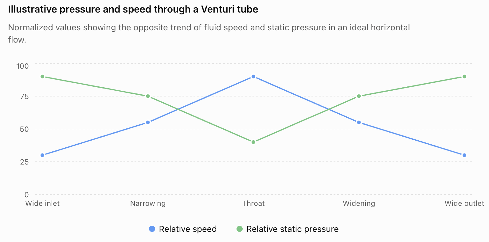
The values above are illustrative rather than measured data, but they show the key relationship:

speed rises → static pressure falls

and when the pipe widens again:

speed falls → static pressure can recover


Bernoulli and Airflow

Bernoulli's Principle applies to gases as well as liquids when the assumptions are appropriate.

Air moving around objects can therefore show pressure differences associated with differences in flow speed.

Applications include:

  • aircraft wings
  • sails
  • roofs
  • spray devices
  • Venturi meters
  • carburetors
  • laboratory aspirators
https://images.openai.com/static-rsc-4/4v7eDY9Nmej2eApXxa0g5xyUydftxBTPZaas8Ul74k7gFvuW3eLNKP3a33S4X3nV-ijYpBfWJuhLAhEimjgT-W0B4QFTA76ofuImrNnQ1Ubyd6kZfzPUZHL3eMX8rknz5pb-X61E2ktYtGC-6F2lYRhbJPRXEVPqyF98DN0KBTcj9glTvLSMsXdMeGUHMTNz?purpose=fullsize
https://images.openai.com/static-rsc-4/3e2IkzLnkkEGygiEIv7iOT-I7Jv8rf-EH3HyriEDuFPOqa2FyWYeJHlG7Qvps0Dw0xLPo7mVhFXQQO5GGiSfY7atcN4eelN-oQhAEuBRcPQdgj6qySZCNoZbO7Z9y79VXxgn7D2KG6L4fBZS9q4Viluf7koVfDLql2ClFQYbT0jDQmyDrrJomalDebs-ISHQ?purpose=fullsize
https://images.openai.com/static-rsc-4/2-sevnK2V7Ay9Ho6duAtzSApCnmZ6mnaSHorQLE8AioIdB6Gl7s360RuGvk8hDg1VQaOHLzNTaaCV--Nt3jHX69hhNuNlPg1ygJE8xeNHHZY8dTkxpFH09l8xsG6Ykf1HUirtA4gO2s7KfzbrroWSApIYV1Z7uYzCd1ZAncOsEUZO_KwEDS4MxZcCTJRcd1D?purpose=fullsize
6

Aircraft Wings

Aircraft wings provide an important application of fluid dynamics, but they require a careful explanation.

Air moving around a wing creates a pressure distribution over its surfaces.

The pressure is typically lower over much of the upper surface than over the lower surface, producing part of the upward aerodynamic force called lift.

https://images.openai.com/static-rsc-4/IfyjilRgNhFQtSCYXIsdN_Z3wYyxc95Vh2-NW_AhWEgP_5XWM132CTORWaV1WcnvHuAfYjV6Q0Vq9re73cLjoLHQ6GRUbAwT8hwaOJ6GG6DZzQcVig3LeTWHDBulf-0gdI80UqCvIh6VJFX9Nohg3Z-H5oJRTwrtFShCE8CXUY1xlXn-_kV9FtbhxCPUJn3c?purpose=fullsize
https://images.openai.com/static-rsc-4/XkKVQH78m-HoGnrhiwIWcw9hAOQB9ZbDadcZ11U6QvjkJHns0G5kqx9dlQExuyjZCCQarvT1UkuGUMNVyqpwZI19sQ53Kxyll8CVFQcz394uqbVNiQtN_wWAJmwPHlZiTdygSb5GwuJEsyLu95_vjEbpLsCKIh0fXUK_qR_p0cnnbvK4FTM-jdCkI9pYKWe0?purpose=fullsize
https://images.openai.com/static-rsc-4/NkRQjr3YVxXbIy9MO2w1TxKzc5-fQxImRl1LZCdWg1D3lCEpGazWwhp8B0ujD8lXA52QzWoQoCSyz_NAmclzUAWdwytKcCIJJIQWOJfFPRuOKqR7ak_yPB_0Jm9_h2KAZ3-dK_3bkdwEbGtbpHBGht2wQRvkjqoTANYndYwuq2l5Lnjg-YXuGDpZMk3YnWby?purpose=fullsize
6

Bernoulli's equation can help relate regions of different airflow speed to pressure differences.

However, it is incomplete to say:

"Planes fly only because air moves faster over the top."

Lift also involves:

  • wing shape
  • angle of attack
  • airflow deflection
  • circulation
  • pressure distribution

Bernoulli's Principle and Newton's laws are consistent descriptions of the same fluid behaviour, not competing explanations.


An Important Wing Misconception

You may have heard this explanation:

"Air travelling over the top of a wing must meet the air travelling underneath at the back."

This is called the equal-transit-time explanation, and it is incorrect.

Air particles separated at the front of the wing do not have to arrive at the trailing edge at the same time.

A better explanation considers the complete airflow and resulting pressure distribution around the wing.

This distinction is important when using Bernoulli's Principle correctly.


Spray Bottles and Atomizers

Some spray devices use fast-moving air to help draw liquid into an airflow.

https://images.openai.com/static-rsc-4/nvbo4jTM9M0sVflaNmFmfW4C5nE3pK8lyyyPgIO-mjAZ1vOxQLkbaQRPUEhUdED1a2KUNW1Wbun4B1KzpxJ6oMM_YgTaXVrEtLslB6O1WsKRKy9ptwm0nb9EN2ITGNKXy1AzWfrrml5RbGB62WxhQyMkrXLj2HFublmifxsNRxT5PehyLrt_nkdFdXNA4LP2?purpose=fullsize
https://images.openai.com/static-rsc-4/dbPi83t7QVsgZVJjdiX1Pw5vAkX6tIqeXbaJoEdAIu-drz_roQO4-DZgU-PKD_NWtGmHdvN74SSTpkrdHtBmjEJxh-_fibf1zTURrlCSm1YSTjU4vG0QvCb-Zj_OsmK9QH5f6Fc0ylsS5evI2Ffsh0HVFRlVBzm-HcN5dKUY3UIXDgJMFSKt--rVCUtZ3f8V?purpose=fullsize
https://images.openai.com/static-rsc-4/Ck_qNYbmAr_pW9sVgSSy-AUmv3a_uxB-8PaA9PzdSn7yaVLBqdXbeQ9mzuzPWy_tdEZtF5akUhGdG_4dQkD9mTNSyCbJZOY-EPxPRq6Qx11hbhAIApFZuHMXVCviq21YJan1wyLuWKE_l-_-q-pMu_cxfXem4dtCe15LAe5G047VOanzgCpr3w_QxkUB4bsh?purpose=fullsize
5

Fast air moving past the top of a tube can be associated with lower static pressure.

If the pressure acting on the liquid elsewhere is greater, the pressure difference can help push liquid upward.

The moving air then breaks the liquid into small droplets.

This principle has been used in:

  • perfume atomizers
  • paint sprayers
  • laboratory equipment
  • some fuel-delivery systems

Chimneys

Moving air across the top of a chimney can influence the pressure near its opening.

A pressure difference can help encourage gases to move upward through the chimney.

https://images.openai.com/static-rsc-4/AI9UrDTk8yy7_MUQ8v_AE9zgiBJFkco6ZS-AgFbcAky2w6n5zmjvvl6DwRratYUswdLVCSxEncbKXZ9IlkutedXXQWd2y_hAgyJOHVFz5MyPqLADiKXXzaVWPTiHkaZdw4JkUQoaiOa1WMbZ-Y1kXP3ZY823K8ux44dffcIFVlIuFv5qpIAdngxnzZhMFQty?purpose=fullsize
https://images.openai.com/static-rsc-4/K2u7XerR2T0YCvZn32CuKul80-PXw0lYWmmO417QwpqCjYyKwVG5ByZTFtZsyL7-KT95uyyOoD9reCxaTybW2SJUfKkgNWqJBbd9bTi0PMZRMx9tfB8lEn4Mw6XzfZqbs4tq6qJ51BW-cMDYybJN0c15tuKqXSTB-WJtj0kVQd8AVVerMvCeJpz5wvUFmfPE?purpose=fullsize
https://images.openai.com/static-rsc-4/ztybAhcyC0NjtyNhT_Q5xhordslEKQQqiW2wYXlo5U_rcYE-7fRWPpqAxnJRin9zoC08tkhWk1KdOgbkYaUwZZRPnCqFuCRfNakNq5jAeTIsCKPEHMW0DOX_Tsq5Cnr9sNVaUzr8IaUIWPXBRlBW09E1dGLgdVCLfellHYsWgW_QEawLlrDk-kopeqCzl150?purpose=fullsize

However, chimney draft is also strongly affected by buoyancy because hot gases inside the chimney are usually less dense than cooler outside air.

This is a good example where several fluid principles operate together.


Strong Winds and Roofs

Fast-moving wind around a building can create pressure differences across surfaces.

https://images.openai.com/static-rsc-4/wyAIUYHaM6b0c_INmssafFXOQLssxshYqgHgpwNdq4F__JFWeti64nIQUy0NxIuwIWJWPq00N-bUHYyQX7FtDVNe5mElLTjZTaoKfq4TPUjLFeSdZx0x3OSxzqDyj1V_xUVl7CQfj0T5Squi9tlUDNY40V-OhZCBrkaXWlLEMTB4IIeMq9bSXbi61DGN747a?purpose=fullsize
https://images.openai.com/static-rsc-4/QkltsQSvZw6g63Kiv-LwP0rsnvMMhcOh3YOovlsK1vX0kfIQSIcAXzoZQgwBBHb-WWCBltTO7Yu782h7vvXyCQkQ3HWG4XoJs_EfWeqv_JtU-zMlPS43eqkDJ15f7I9-ExtGmR8WIw5AH2bD5NwrW4BTocs1ib-naM1-MTRnLExjUb2ERCUPTwWcWsKUXk3W?purpose=fullsize
https://images.openai.com/static-rsc-4/nKjhX0JitIYQfeSazkweOTX3X4ddeOYdrHTfN4SkBKOX21K_OVFlzmDIYrEYuBxw8cIpnBPOZCPepIVvlSeCucQLx9jTSVXuJNM_ssyE5wrFTjxENytsGTi04hioOCdYwVJVLzv0xIad2Aq2rLGIkNqYxELNwowjVAETqjKCNZlW8w_CXmbtnSzECE_sjkTU?purpose=fullsize
6

These pressure differences can contribute to forces on roofs.

However, real wind flow around buildings is turbulent and complex.

Engineers therefore do not rely on a simple Bernoulli statement alone. They consider:

  • external pressure
  • internal pressure
  • turbulence
  • building geometry
  • wind direction
  • structural strength

This is an important example of applying a scientific model while recognizing its limitations.


Sailing

Sails interact with moving air and can create pressure differences across their surfaces.

https://images.openai.com/static-rsc-4/3e2IkzLnkkEGygiEIv7iOT-I7Jv8rf-EH3HyriEDuFPOqa2FyWYeJHlG7Qvps0Dw0xLPo7mVhFXQQO5GGiSfY7atcN4eelN-oQhAEuBRcPQdgj6qySZCNoZbO7Z9y79VXxgn7D2KG6L4fBZS9q4Viluf7koVfDLql2ClFQYbT0jDQmyDrrJomalDebs-ISHQ?purpose=fullsize
https://images.openai.com/static-rsc-4/ujmgI6d0zcQKKSCPBq2-1S2ALWkqzk53dlY-5cIl_8L_BCBC39Mo3X4k9pAuDVU_v1muwNVA9Mw0tjYe2Sk0fERqpVIJHUsHwCD8JPjJq5ECStDorvaUZ6gK3RbCPocb6D6ig5WtvZc_rQQwbwmQhNWvZGVENck1uXg_ZiEh4Tc2JxIFhdr7kPN4SpJ39f2y?purpose=fullsize
https://images.openai.com/static-rsc-4/otkHywqj6HDT03I9KLyDm9-kH2yOwgn_YWQUsfF4yKfZltrX2WHGJoJZjDVCpsqmcSw1i19NXx0P4wfrfKw4oR7Ublk1JEBsU7hBxNQfYth-MsUqP00wKFgCfUqFA4OSXmX1VM9ScRLu-0RHEFO1zJg6MYLIpXD0lcPZklTNjyXg-ozRfHrDDXqf_m6kEqE2?purpose=fullsize
6

The resulting aerodynamic force can be resolved into components that help move the boat.

As with aircraft wings, the complete explanation involves:

  • pressure distribution
  • airflow deflection
  • sail shape
  • angle to the wind

Bernoulli's equation can help describe the relationship between airflow speed and pressure in suitable parts of the flow.


Pitot Tubes

Aircraft and other systems can measure fluid speed using differences in pressure.

One device is a Pitot tube.

https://images.openai.com/static-rsc-4/eMkyUoXMyAlXTBcI61PgfnGKlAnkTxOTwEpKVvV8qeSBCG9Q1IKbXQalMSAChulzsqaSliDMXsi-_P-TK4kAbhTPMWODYz9AmAI8vRF7k8J5F1AGf9eJ1xctU_a2XZT1bFLQhywVj37xiEqj_lMz4woMFej4hS25a1-6P2L1Rct8jswY0scNLNoMmcUx3wO9?purpose=fullsize
https://images.openai.com/static-rsc-4/h-k_IxIKcr6Fdv9-NlRJWnlLz267U4IzT3ou4IJ_nECLHUjnOMk8FynmDvwDsfFdIAG_LJEhuqhL7HYKJPALRxrcjtoWqsv-Eg0nDKsJmEatlfZAjclgEx40_Xof5brP99XCPlZEHEOvzHzYcP1PxD_J_gOUrVnXLGZRUiBgmF2JnL1unY66-9GuMc1_eqiw?purpose=fullsize
https://images.openai.com/static-rsc-4/lXdnMv6qKhaZBItYS80nKlL-cqHqG31s4T1HSxIefqdWOBdNLIrCdnx9NhtvxmfEGImcXZR10S8CNFY91Q-ytqW_UoRRt35mP4USvjyBMmcbsmS5beqyffJKJNcJgW-bihX2y5fysCCLLmtICq59gv6xHZv1y9PwDiVa6RHxEF1hpkfC856dCrzFvEHXsgEZ?purpose=fullsize
4

A Pitot-static system compares:

  • static pressure
  • stagnation pressure

The pressure difference can be related to fluid speed using Bernoulli's equation.

This allows aircraft instruments to determine airspeed.


Worked Example 4: Using Pressure Difference

Air moves through a horizontal system.

At Point 1:

v₁ = 10 m/s

At Point 2:

v₂ = 20 m/s

Use an air density of:

ρ = 1.2 kg/m³

Calculate:

P₁ − P₂

Start with:

P₁ + ½ρv₁² = P₂ + ½ρv₂²

Rearrange:

P₁ − P₂ = ½ρ(v₂² − v₁²)

Substitute:

P₁ − P₂ = ½(1.2)(20² − 10²)

P₁ − P₂ = 0.6(400 − 100)

P₁ − P₂ = 0.6 × 300

P₁ − P₂ = 180 Pa

Answer

P₁ is 180 Pa greater than P₂.

The faster-moving air at Point 2 has the lower static pressure in this idealized horizontal example.


Combining Continuity and Bernoulli

Some problems require both equations.

Suppose water moves through a horizontal pipe:

A₁ = 0.040 m²

v₁ = 2 m/s

The pipe narrows to:

A₂ = 0.020 m²

and:

P₁ = 130 000 Pa

Use:

ρ = 1000 kg/m³

Find v₂ and P₂.

Step 1: Use Continuity

A₁v₁ = A₂v₂

0.040 × 2 = 0.020 × v₂

v₂ = 4 m/s

Step 2: Use Bernoulli

Because the pipe is horizontal:

P₁ + ½ρv₁² = P₂ + ½ρv₂²

Substitute:

130 000 + ½(1000)(2²) = P₂ + ½(1000)(4²)

130 000 + 2000 = P₂ + 8000

Therefore:

P₂ = 124 000 Pa

Answer

v₂ = 4 m/s

P₂ = 124 000 Pa

So:

area decreases → velocity increases → static pressure decreases


A Problem-Solving Strategy

When solving Bernoulli problems:

Step 1: Draw or examine the system

Identify Points 1 and 2.

Step 2: Record the known quantities

Look for:

  • P₁ and P₂
  • v₁ and v₂
  • h₁ and h₂
  • ρ

Step 3: Ask whether continuity is needed

If pipe areas are given, you may first need:

A₁v₁ = A₂v₂

Step 4: Write Bernoulli's equation

P₁ + ½ρv₁² + ρgh₁ = P₂ + ½ρv₂² + ρgh₂

Step 5: Cancel equal terms

If the pipe is horizontal:

h₁ = h₂

so the gravitational terms cancel.

Step 6: Solve

Substitute carefully and include units.

Step 7: Check your reasoning

Ask:

  • Did the fluid speed increase?
  • Should the static pressure therefore be lower in this ideal horizontal case?
  • Did the fluid move higher?
  • Should gravitational potential energy have increased?

A physical check is often as important as the arithmetic.


When Does Bernoulli's Equation Work Best?

The simple Bernoulli equation assumes an idealized situation.

It works best when the flow is approximately:

  • steady
  • incompressible
  • low in viscosity
  • considered along a streamline
  • free from significant energy additions or losses between the selected points

Real fluids experience:

  • friction
  • turbulence
  • viscosity
  • pumps
  • turbines
  • heat transfer

These can change the fluid's mechanical energy.

Engineers therefore use extended forms of the energy equation for complex real systems.


Real Pipes Lose Energy

Imagine water travelling through a long pipe.

Friction between the moving fluid and pipe walls causes mechanical energy to be dissipated, mainly into internal energy.

Therefore, real systems often experience pressure loss.

https://images.openai.com/static-rsc-4/O-TDHP8KQ7FgK2IYm44NEi4L9JoAlpUR0tQoeyy-5-sT4KVOrxvQTcAm8Zmn9LH7nFXAHqzJs10Uhn4os7W8Ns3BCaEIE34yHnL0-mx5ImRiE2X4s-gpsdNgk_-pJsOcOq2YvoJyHfsO_bL2MBgzNlHP1WhGsxxSpcQktVufR6Koq8buk3QCnK-x8iOu-nvP?purpose=fullsize
https://images.openai.com/static-rsc-4/qF8ta-VCRV-w24Cwbdml9brgunPO9YXRWe3KKS_w-0fHzgMG1ITEW0uHxBA2OLzUGdYb2JNZkGTluibJPKESAxnEz-7OacnJ5dLalaNRIJCK0xkx8PJ4duD2aErO7-pHvZKhRuDArPDWIlOZUOvDfCg3N9Prfvf5mys_qfwkAcKAIHiOGiymYZWyokcz8PNQ?purpose=fullsize
https://images.openai.com/static-rsc-4/1oek8q_IZm32fMNjCYqMxz0epVeal7eqjkcnwT_PxlvtYes7lE3fQf1vFMu6V5-jz4mmK9Pprdw-_X3X_lYuDQ88CBCvf70h4VNZ1pzpdmeBChCajQeYXlnALwBVzhcaOSog7Dv1skiJ-fovTtz0O61RG3vqRPcysm-VXVyiCimywbomKFjILN2hH1NCq6xG?purpose=fullsize
4

Factors affecting pressure losses include:

  • pipe length
  • pipe diameter
  • fluid viscosity
  • surface roughness
  • flow speed
  • bends
  • valves
  • turbulence

So real systems may not behave exactly like the ideal Bernoulli model.


Pumps Add Energy

A pump can add mechanical energy to a fluid.

https://images.openai.com/static-rsc-4/qNHLQSqHnLr4UhYHzUVoQB9ydah6lodFbEPWv9nkiLpi_ZMXprMXU3kg_F7Gk2nHDU0UxqMAlHgvfHqND3HG0LSodbUzkOHOwJbJ-ETKyVsjlLrcUeXiDSi108ROrnd15jv3WG4nmMXe5MlUGMVyAv5YY_Plql5pIOFJdRQw3oF6tbsh6VYK6a1_WhcUR-Fu?purpose=fullsize
https://images.openai.com/static-rsc-4/s3t1ra80sd2PLd6jPqwjjEeuRx-yOiXhkhrfTVXupv2yDqvBp-PYlRuJbqhyq2QPn2zYrNtLIawCZmxB7jycALw14s7_W5KQeuI7Os4sC52NPQe_uak54t-Ou-_bGeH4KKLw7Tz13-6NdvTZ9kQhbU3OS5kG6H0uwtWxJb4KGCluPI0kVxEH62y4ifkLpjxl?purpose=fullsize
https://images.openai.com/static-rsc-4/HNMV0vFb_HR9VZxCtwn3uqZItla9S7xqAzU-vGmiDBg376dwMQ9RZ1TsiM8VWRHwxjTaqD_MnR1xYs0903oirxjNnDYL3SWboT482uNqOkHqb48f8vuTgUG4I3o16EWvK8rKEgK0ag_9ccRHuSrne4RE4KaZS5tEY9lSrTPEEh5Jp0Hg84oSrh97J7YGso5b?purpose=fullsize

For example, a pump can:

  • increase pressure
  • increase flow rate
  • move water to greater height

In such systems, the simple Bernoulli equation between points on opposite sides of the pump must be modified to include the energy supplied by the pump.


Bernoulli in Engineering

Bernoulli's Principle is important in many fields.

Civil Engineering

Used when analysing:

  • water distribution
  • pipelines
  • dams
  • drainage systems

Mechanical Engineering

Used in:

  • pumps
  • turbines
  • nozzles
  • Venturi meters

Aerospace Engineering

Used in understanding:

  • airflow
  • pressure measurements
  • wings
  • aircraft instruments

Marine Engineering

Used in:

  • propellers
  • hull flows
  • underwater systems

Biomedical Engineering

Fluid-dynamics principles help scientists understand:

  • blood flow
  • pressure differences
  • medical flow devices

Bernoulli's Principle is therefore not just a classroom idea—it is one part of the foundation of fluid engineering.


Common Mistakes

Mistake 1: "Fast fluid always has low pressure."

This is too general.

The simple inverse relationship is most useful when comparing appropriate points in the same flow, especially at similar heights under ideal conditions.

Pressure also depends on height, energy losses, pumps and other factors.


Mistake 2: "Narrow pipes have higher pressure because the fluid is squeezed."

For steady ideal horizontal flow, the fluid accelerates through the narrower section.

Its kinetic energy increases, while its static pressure decreases.


Mistake 3: Confusing pressure with kinetic energy

Pressure and fluid speed represent different forms of mechanical energy in Bernoulli's equation.

Greater speed does not mean greater static pressure.


Mistake 4: Forgetting height

Bernoulli's equation contains:

ρgh

If height changes significantly, it cannot simply be ignored.


Mistake 5: Forgetting to square velocity

The kinetic term is:

½ρv²

not:

½ρv

A small increase in velocity can therefore cause a relatively large change in the kinetic term.


Mistake 6: Assuming Bernoulli creates energy

Bernoulli's Principle does not create extra pressure or speed.

It describes how mechanical energy is transferred between different forms.


Mistake 7: Using the "equal transit time" explanation for wings

Air travelling over and under a wing does not have to reconnect at the trailing edge at the same time.

Aircraft lift requires a more complete explanation involving the entire airflow and pressure distribution.


Mistake 8: Ignoring friction in real systems

The simple Bernoulli equation describes an idealized flow.

Real pipes lose mechanical energy because of friction, turbulence and other effects.


Mistake 9: Thinking Bernoulli and Newton give competing explanations

They are compatible.

Pressure differences and changes in fluid momentum are connected aspects of the same physical process.


Check Your Understanding

1. Recall

State Bernoulli's Principle in your own words.

2. Energy

Name the three energy terms represented in:

P + ½ρv² + ρgh = constant

3. Predict

Water moves through a horizontal pipe from a wide section into a narrow section.

Predict what happens to:

a. fluid velocity

b. static pressure

Explain your reasoning.

4. Explain

Why does static pressure decrease when fluid speeds up in an ideal horizontal flow?

Use the idea of conservation of energy.

5. Calculate

Water flows through a horizontal pipe.

At Point 1:

P₁ = 160 000 Pa

v₁ = 2 m/s

At Point 2:

v₂ = 4 m/s

Use:

ρ = 1000 kg/m³

Calculate P₂.

6. Height

Water moves upward through a constant-diameter pipe.

Its speed remains approximately constant.

Explain what happens to its pressure as its height increases.

7. Apply

Explain how a Venturi tube uses differences in:

  • cross-sectional area
  • velocity
  • pressure

8. Airflow

Explain how Bernoulli's Principle can help describe pressure differences around an aircraft wing. Why is Bernoulli alone not a complete explanation of lift?

9. Combine Principles

Water flows through a horizontal pipe.

At Section 1:

A₁ = 0.060 m²

v₁ = 2 m/s

P₁ = 150 000 Pa

At Section 2:

A₂ = 0.030 m²

Use:

ρ = 1000 kg/m³

First calculate v₂ using continuity.

Then calculate P₂ using Bernoulli's equation.

10. Challenge

A student says:

"Bernoulli's Principle means that whenever something moves faster through a fluid, the pressure everywhere around it must decrease."

Explain why this statement is too simplistic.

Include at least three conditions or factors that must be considered.


Key Terms

  • Bernoulli's Principle – conservation of mechanical energy applied to suitable fluid flow
  • Bernoulli's equation – relationship between pressure, velocity and height in ideal fluid flow
  • Static pressure – pressure associated with the local thermodynamic state of the fluid, distinct from the kinetic contribution of bulk motion
  • Dynamic pressure – quantity ½ρv² associated with fluid motion
  • Pressure energy – mechanical energy associated with fluid pressure
  • Kinetic energy – energy associated with motion
  • Gravitational potential energy – energy associated with height
  • Venturi effect – pressure change associated with fluid acceleration through a constriction
  • Venturi tube – device containing a narrowed section used to produce measurable pressure differences
  • Streamline – path representing the direction of fluid flow
  • Steady flow – flow whose conditions at a particular point do not change significantly with time
  • Incompressible fluid – fluid whose density remains approximately constant
  • Pressure loss – reduction in mechanical pressure associated with friction and other losses
  • Pitot tube – device that uses pressure measurements to determine fluid speed

Key Takeaways

  • Bernoulli's Principle is an application of conservation of mechanical energy to fluid flow.
  • Bernoulli's equation is:

P + ½ρv² + ρgh = constant

  • The three terms represent pressure, kinetic, and gravitational contributions to mechanical energy per unit volume.
  • In an ideal horizontal flow, greater fluid speed is associated with lower static pressure.
  • Continuity explains why fluid speeds up when a pipe narrows.
  • Bernoulli explains how this change in speed is related to pressure.
  • Together:

narrower area → greater velocity → lower static pressure

for an ideal horizontal flow.

  • If fluid moves to greater height, some mechanical energy may be transferred into gravitational potential energy.
  • Bernoulli's Principle helps explain and analyze Venturi tubes, nozzles, pressure measurements, airflow, spray systems, and many engineering systems.
  • Aircraft lift should not be explained using the incorrect equal-transit-time idea; the full airflow and pressure distribution must be considered.
  • Real fluids experience viscosity, friction and turbulence, so real systems may lose mechanical energy.
  • Pumps can add mechanical energy to flowing fluids.
  • Bernoulli's equation is a model with assumptions, so it should be applied only when those assumptions are reasonable.


4. Lift and Aerodynamics

Learning outcomes
  • I can explain how pressure differences create lift.
  • I can describe how airplane wings generate lift.
  • I can identify factors that influence aerodynamic performance.
  • I can explain the relationship between airflow and pressure.
  • I can apply Bernoulli's Principle to flight and sports applications.

When an airplane flies, enormous forces act on its wings. The aircraft may have a mass of many thousands of kilograms, yet airflow around its wings can produce enough upward force to keep it in the air.

The study of how air moves around objects is called aerodynamics.

Aerodynamics is important not only for airplanes. The same principles help explain the motion of:

  • cars
  • bicycles
  • birds
  • drones
  • racing vehicles
  • footballs
  • golf balls
  • tennis balls
  • sails

A central idea is that airflow creates pressure differences, and these pressure differences can produce forces.

https://images.openai.com/static-rsc-4/XkKVQH78m-HoGnrhiwIWcw9hAOQB9ZbDadcZ11U6QvjkJHns0G5kqx9dlQExuyjZCCQarvT1UkuGUMNVyqpwZI19sQ53Kxyll8CVFQcz394uqbVNiQtN_wWAJmwPHlZiTdygSb5GwuJEsyLu95_vjEbpLsCKIh0fXUK_qR_p0cnnbvK4FTM-jdCkI9pYKWe0?purpose=fullsize
https://images.openai.com/static-rsc-4/_g24DCwgKxzbtpFuxT_lZayMx8q1XSMacevlztUbD5j8pBuXo2s9dr592YGGK7AJQcx-uK8zl3XB7bfmWzachsBeBX_qlzY3VJk4sKqqdZZxtd5PgV0BtDRC5HeaiguBD0qWndDgf16fWBbCZs4W7H7mmyj-IH8PBu6D5a3i7wnHU0b0EYYAqJ5EBsWEPn2t?purpose=fullsize
https://images.openai.com/static-rsc-4/Mi2Z4gz4sJLxcYHQorKKWDX710vrdUuN5j64mk9nPT1dHaJzW3aBY61JLpFOlNX7j38dcIbDh84VLhOv7KX9nJAfe-UMz8TKr34j6tcUZ8ZBfXUOCJ9KxOD5ldwLHOFv7eErPoc5UhooB6IhxV7SNmYPkgxtQUI35wiTTcT0XPp2BYqYTyoXpWAyNVDvSb5Z?purpose=fullsize
7

What Is Aerodynamics?

Aerodynamics is the study of how gases, especially air, move around objects and how that motion produces forces.

When an object moves through air, the air interacts with its surface.

These interactions can produce forces such as:

  • lift
  • drag

Aircraft are specifically designed to control these forces.

A racing car, bicycle helmet, football and aircraft wing may look very different, but all are affected by the movement of air around them.


The Four Forces of Flight

Four major forces act on an airplane during flight:

Lift

Lift acts mainly upward and is produced largely by the wings.

Weight

Weight acts downward because of gravity.

Thrust

Thrust pushes the aircraft forward.

It may be produced by:

  • jet engines
  • propellers
  • other propulsion systems

Drag

Drag acts opposite the aircraft's motion through the air.

 
                     LIFT
                       ↑
                       │
                       │
        DRAG ←──── AIRCRAFT ────→ THRUST
                       │
                       │
                       ↓
                     WEIGHT
 

During straight, level flight at constant speed:

lift = weight

and:

thrust = drag

The forces are balanced.

https://images.openai.com/static-rsc-4/Mi2Z4gz4sJLxcYHQorKKWDX710vrdUuN5j64mk9nPT1dHaJzW3aBY61JLpFOlNX7j38dcIbDh84VLhOv7KX9nJAfe-UMz8TKr34j6tcUZ8ZBfXUOCJ9KxOD5ldwLHOFv7eErPoc5UhooB6IhxV7SNmYPkgxtQUI35wiTTcT0XPp2BYqYTyoXpWAyNVDvSb5Z?purpose=fullsize
https://images.openai.com/static-rsc-4/zYVBVxxBP0yc_05xc8mEBXem3Lx4m3vGmdCGFvz2nbIRhJBKbPfDWLyE7-oXCh6z6iP0J3UkjLIgEpKIFIGH2zLltXlGWVREm5XMsDbuDV7bR4TbbFnHURwVHKt8r9o1H4JVTNCSt4BYyVwC3iRZZxUktlliWJqrLPdDxW4OFx6XQCHSEtGRvp9iL0uvQ2xl?purpose=fullsize
https://images.openai.com/static-rsc-4/QYPaEbhDsjoWNqzNUu9BPoexeT5OpHhmrH7Vqeww7hTGJkOkSV9bpTi-hxZKOhplfT20BtEKwvTg1hpvM1sW-NhUmmTYxAKxCMIUUOv1FdKbit1Eu2apkHd_Mna0blZQ3wf6uQ3hYb3wWCqRKOTmUkmfSToxSD3JO4cHtC2yk1kbqS_aZCxiN0V8Yk6gXHiq?purpose=fullsize
5

What Is Lift?

Lift is the aerodynamic force acting perpendicular to the relative airflow.

For a normally flying airplane, much of this force acts upward.

Lift is produced because airflow around the wing creates a pressure distribution.

The pressure is not the same everywhere around the wing.

Typically:

lower pressure occurs over much of the upper surface

while:

higher pressure occurs over much of the lower surface

The combined pressure forces produce a net aerodynamic force with an upward component.

That upward component is lift.


The Shape of a Wing

The cross-sectional shape of a wing is called an airfoil.

https://images.openai.com/static-rsc-4/kfnkcNQe3NH9rx6s07W6pYY3gBDzlmIgQ0QEC-lsTJH1Ysyq3j2UVvfzauSqQWp1vxc9u9FV5GOWoRqnrYjPBUUwjXWQ_zkJjbMQ8AnZRRcq0o5oc_7annmwsnfOLYAPYmVEMz1tMD11ZWo89baxVTsb5NLpITTDN1rlwWWWFT1b-ZhTb4xj3l7SInGXEybx?purpose=fullsize
https://images.openai.com/static-rsc-4/GQI-EASQxgrQdzXRNEzpi2rKqzlcMWUEa2nLhveRY6bCeW-BAPnUijg30ke3g5F4DWzMblMWkDpFgY8m4wve9ajfUdXCdfNASo5d_1YanK2PXQ7UYqBdl3NmJF3wHiDJTsmtIJETpAq5a5_ej0rm5WfLCXpptLHAowUJu5UVsKoprj6qyPdYrdM_h0nHN_7N?purpose=fullsize
https://images.openai.com/static-rsc-4/lUgXlz4dTvdjLlHXpFHJb1wv5SELGaQyhlySdkVSUYTZFBHtii9lGyY3BSrw0QjaI09GdT5Flcmj8F884op9Oz2SaIBkviJ3ge9xD68Ae5MfmnqXQObK5_N9YQfFRMxlJflo5SwLqVMsINDgSCwEHcqhNKkj8_B7gfJDx3KcwjI0rFTrC9idniRXPku3ELt2?purpose=fullsize
5

Important features include:

  • leading edge – front of the wing
  • trailing edge – rear of the wing
  • upper surface
  • lower surface
  • chord line – imaginary line from leading edge to trailing edge
  • camber – curvature of the airfoil

Different airfoil shapes are designed for different purposes.

For example, aircraft designed for:

  • high speed
  • heavy loads
  • gliding
  • aerobatics

may use different wing shapes.


Airflow Around a Wing

As an airplane moves forward, air flows around the wing.

The wing's:

  • shape
  • angle
  • speed through the air

cause the airflow to change direction and speed.

https://images.openai.com/static-rsc-4/f-HvH6soaANnviqpop3fuYAqX8OyBWbPa9KfMQI0HviSOhCxsv677njoV03Gm8pUN6LXRBfzlRbATsiV6WFy86ADefGlFZQefh9Yw8EvBRUF2DQeEqJ8D8nRBbSaGN2ssSJUoEh_brIMl-8_33mU7pu-DKKjwNA5q1iTOOmX8tFKKGW8x0OaltAJw9XzZIjU?purpose=fullsize
https://images.openai.com/static-rsc-4/qIv19z8S2fYEqPKqsgBsl9x7gFo7BQh76Sg-PsLg77kSvDjR5cspWN1_P6XMFab5f6dRvjMBw7U6MeaWnpbSJOAchol4SzpycNgHtQa-F41-Ql84NDDjvuBbYD6r0drdK8o5p2to7subp2onzBoedsGSMPw_gVdQq2AevO2vpA80cekROJ-3tsAEhMqvehpV?purpose=fullsize
https://images.openai.com/static-rsc-4/NkRQjr3YVxXbIy9MO2w1TxKzc5-fQxImRl1LZCdWg1D3lCEpGazWwhp8B0ujD8lXA52QzWoQoCSyz_NAmclzUAWdwytKcCIJJIQWOJfFPRuOKqR7ak_yPB_0Jm9_h2KAZ3-dK_3bkdwEbGtbpHBGht2wQRvkjqoTANYndYwuq2l5Lnjg-YXuGDpZMk3YnWby?purpose=fullsize
6

The airflow around the wing develops a characteristic pattern.

The pressure distribution associated with this flow produces lift.


Bernoulli's Principle and Lift

Recall Bernoulli's equation:

P + ½ρv² + ρgh = constant

For airflow around a wing, differences in height across the wing are often small enough that the simplified relationship can help us understand parts of the flow:

P + ½ρv² ≈ constant

Therefore, along appropriate streamlines in an idealized flow:

greater airflow speed ↔ lower static pressure

Air often moves rapidly over parts of the upper surface of a lifting wing.

This is associated with lower static pressure there.

If the pressure beneath the wing is greater, the pressure difference contributes to an upward force.


Pressure Difference Creates Force

Remember:

Pressure = Force ÷ Area

Therefore:

Force = Pressure × Area

A small pressure difference acting over a large wing area can create a very large force.

Suppose the average pressure beneath a wing is:

80 500 Pa

and the average pressure above is:

80 000 Pa

The pressure difference is:

ΔP = 500 Pa

If the effective wing area is:

20 m²

then:

F = ΔP × A

F = 500 × 20

F = 10 000 N

So a pressure difference of only 500 Pa can produce:

10 000 N

of force over that area.

This shows why relatively modest pressure differences can be extremely important in flight.


Newton's Laws and Lift

Bernoulli's Principle is useful, but it is not the whole explanation.

A wing also changes the momentum of the surrounding air.

The wing causes the airflow to leave with an overall downward component.

https://images.openai.com/static-rsc-4/RSk90nR1RtsbyW7Qk8HF06vAzcG19-BcZlW9EzYWBjLTdQ653h29BsXjFfyVK2whZHRXxg2hCqw3RjxMLSWgguGsxJoL0ri5I9LUhu27MoWDThtzWiu-BBuFed6I39nCDVEkdtwEvfMCiyG_CnX1ghLq1cwMYfOlAPrZsSjxYaBsxfpfy9H_YrtXtayBoON6?purpose=fullsize
https://images.openai.com/static-rsc-4/LS1MZ99xvJKS8vSGd6gmQsHgtITBNhueTh3LZWAET7byIKmqrKLLd4bu41D4Rw1aZzae_9UUZN-orfFYn7qkvDt_3BEyecWXeIuSoeYiZOe0Ixl6IRmQ1iPPEfMnTaRW0kuYM4_wCMU9fuMtWR5Oom8OWABGTfTZOYG3Ny2TLgMwWB6jInnsZf0Df1scAaK8?purpose=fullsize
https://images.openai.com/static-rsc-4/l1DKNhViGdnx2MTML4_hvW3RmnqAnNCqEsCZZx0ZhlHqOXE6B_pbUygOD5lK2vCUP6iUcLx7pNax4rlSK01cJ34lAeaEVM4q7yIX20n19PYekO9vDrLEA3ybgW3za2l4nXHz_zWOSpcYwyq2tO5BGNWETR_Sri9whNSRslEma1pFue7OnCJoGOYXu2_pFgXB?purpose=fullsize
4

The wing exerts a force on the air.

The air exerts a force on the wing.

This is consistent with Newton's Third Law:

When one object exerts a force on another, the second object exerts an equal and opposite force on the first.

Therefore:

air pushed downward ↔ wing experiences an upward force

The pressure distribution and the downward change in air momentum are two connected ways of describing the same aerodynamic interaction.


Bernoulli and Newton Are Not Competing Explanations

You may sometimes see arguments claiming:

"Lift is caused by Bernoulli."

or:

"Lift is caused by Newton's Third Law."

This creates a false choice.

Both ideas describe aspects of the same physical system.

The airflow pattern around the wing creates:

  • changes in air velocity
  • pressure differences
  • changes in air momentum

These are all related.

A complete explanation of lift considers the entire airflow and pressure distribution around the wing.


Angle of Attack

One of the most important factors affecting lift is the angle of attack.

The angle of attack is the angle between:

  • the wing's chord line
  • the incoming relative airflow
https://images.openai.com/static-rsc-4/K8WyXn92gZ3YPvlDiEIsQ7RWAHYL8u29-ILGsESDWA-TTRNVpX3rT0o4T0rbsgqnkLqyI2rXTFUpqo-48GmHhKzfLlE3A-8dIRqJLOzf1Bne7aEX9HhRTGKDg7w7LzNf1j93BB1kbCvk4emPds6LHF1uED4SYwkD0uagOXWXYkGoAWINXG4BMyQI5ZtF0EfJ?purpose=fullsize
https://images.openai.com/static-rsc-4/O8WcrV-ZZhl7OZMYfEcWdAr2nk-iUWvo_1AEd6IkKo66pZgiwP2Uf1nSnNz0MpSvtCY7pNkgSGvM5bX5HrVpY25sx-_r_4s8FOuQNxQqcGg2jw8-me7nM2izCTI563et6ZaccNMyIgKkkbxCHrNAoSYnTzRsQJvrXlAaX0BAk_Sf3jPtcdi06kKSQwJWKHD2?purpose=fullsize
https://images.openai.com/static-rsc-4/8_S-ezC5F5BpWYs0nGd0EIZ87r3KNHx_b0lCud33JOSnvx-aFe-KnSaPne8mOiG_Bay41qwjMxo8zwV7VPCEo65tCAD9XFtUB8U1z1gc7WYvll2jEcUiIS1302CZPfeFkMI3bgd9YwKnONPkKzpIKTAUnOowSGbz0EXcxIWaJwp8Dp86c9u6tBrUwIyvpK6o?purpose=fullsize
6

Increasing the angle of attack generally increases lift over a useful range.

Why?

A greater angle of attack changes the airflow and usually increases:

  • pressure differences
  • downward deflection of air

Therefore, lift increases.

But this does not continue indefinitely.


Stall

If the angle of attack becomes too large, airflow can separate significantly from the wing's upper surface.

This condition can produce a stall.

https://images.openai.com/static-rsc-4/TNi7jEOVrhRU48J_LJzhY1EeoHUv6qfriv2ERdbkquNovLNNYztxaheHoTLLmQK0wi-oEGUTycUtkmlvKRMhS6qlvJALlt6mtpr8soPsCWK-ABOITNFViulBxdAnNVWdQp8hnJz9T6lbhhar2tCeoRt_4kH_fRm2PJz3GYHA2ZI5ukvnyMcRhLovv1qnh_yL?purpose=fullsize
https://images.openai.com/static-rsc-4/dUw-peJvAN1JufypDx3g9AgBd_hPWUjkn9D8eiJgfa77dPeZv6dHS0xQxyZCk3pGs_qaYqY0fWcFom5--EjbHpSqMMIq7EzBzItwq1DoU6Y7A0sYUig5S5XXrBHbKuMHDYJa3hQvpmdgapZ109PXfkZWDpxItnyN1d1o9k7pEB1XJhFWkY6WpcCAVJUtpo_-?purpose=fullsize
https://images.openai.com/static-rsc-4/Vqm6h_0HIVyah6iZxLABn_RvK2UMqu8ZRVQYKl8cmLl0NsHhnCgeQ0nP0rSQTNMcCt3lFRe4zpcphicJGVCiE8TG2rCiroqbN61DDk3wuV0lORzr8Thu_wQOoAc24u5BEgBLSkUKBPSDmCVp2OSUOWmCCh5y9LUCXyIeluZVZ3gMmv22evybN1HBb-6ERfbq?purpose=fullsize
4

During a stall:

  • airflow becomes strongly separated
  • the pressure distribution changes
  • lift decreases significantly
  • drag usually increases

A stall is primarily associated with exceeding a wing's critical angle of attack, not simply with flying below one particular speed.

However, slower flight often requires a larger angle of attack to maintain the necessary lift, which is why low speed and stalling are closely connected in many flight situations.


Airspeed

Airspeed strongly affects lift.

A simplified lift equation is:

L = ½ρv²ACL

where:

  • L = lift force (N)
  • ρ = air density (kg/m³)
  • v = airspeed relative to the wing (m/s)
  • A = wing area (m²)
  • Cₗ = lift coefficient

The lift coefficient depends on factors including:

  • airfoil shape
  • angle of attack
  • flow conditions

Notice that velocity is squared.

L ∝ v²

if the other quantities remain unchanged.

This means airspeed has a very strong effect on lift.


Example: Doubling Airspeed

Suppose all other factors remain constant.

An aircraft increases its airspeed from:

30 m/s → 60 m/s

The speed doubles.

Because:

L ∝ v²

the lift changes by:

2² = 4

So the aerodynamic lift predicted by the simplified relationship becomes four times as large, assuming the lift coefficient, density and wing area remain unchanged.

In real flight, pilots and control systems adjust other variables, so actual lift does not simply quadruple whenever speed doubles.


Air Density

Lift also depends on air density:

L ∝ ρ

Denser air can produce more lift under otherwise identical conditions.

Air density generally decreases with:

  • increasing altitude
  • increasing temperature
https://images.openai.com/static-rsc-4/1KxNTrn0yMCzCf5Pi0xl5yGlaZH9qEQAwL-4ebdRdItwpzHbv8UCQcilGFZbPEu7muLll7KtoPIYVoEahzFhlRVxLnrDkAoLwd11YNOVXyMou3pmmEdn5Bms9W7skycONldFKTnwszGW5EiDGNYEHK5jYzAUCIbwhXeggwlJ3CAJbICKU3MAIp0AqZyRxf0H?purpose=fullsize
https://images.openai.com/static-rsc-4/Ul6DL6JEvG5YjOJxhpnyi_r_3j_xw9sOR-9nrWeatY1pW1gdEgGQouQDGJz-_iedOW8g7TLH-UdFOyRj_RkoYK86ZSiF4FlGJUZEYdUPrTpTvMq2eFZChXwcuk3VLmBdU6LvQXBN9VBuzId2hiILWzgRWaA9P2dVS8lFTcnlOFoA1D8fJfwdc9lEwkbZ1-HV?purpose=fullsize
https://images.openai.com/static-rsc-4/trQt_UFo1adILuCc6jieWrN3WQscN6Pnwynf3jkRAdfPuwfwSXd1Lart57WnnKuqA6nKd3836Xd9k3qmJ_gJHpmYpPxAbcSq7hH4JvLZI9cLSgrrmkNmDA9kkyqIj61MEMz4I5kdHlF4BBPTHUGHahz9fPDhiYmr2hYm5fRhmg24v8DwFlPtzR-CXu-SpMhs?purpose=fullsize
6

Therefore, aircraft performance can change with:

  • altitude
  • temperature
  • weather conditions

In less-dense air, an aircraft may require a greater true airspeed or other adjustments to produce the same lift.


Wing Area

Lift also depends on wing area:

L ∝ A

A larger wing can interact with a larger amount of airflow.

This is one reason aircraft designed to carry heavy loads often have large wings.

Compare:

  • gliders
  • passenger aircraft
  • fighter aircraft
  • cargo aircraft

Their wing designs reflect very different performance requirements.

https://images.openai.com/static-rsc-4/qUMuxizyHpa2XDsMl5PW6-4e8oibMYrJ19Dqr_7dU01MCn5g2V3SHx9jmisoJnT8Ty0joQmr6R3JPOqCwEBXOm_BEWAroyrF1ieiNVhgkzxFsc1M_8UHeHSpNussqIxQiHPlF2f5H2QfXb6zZa4Tq51-rXvplQvKpOQpfxwR3K41rnLOP0eyEmUBXqcpc9gA?purpose=fullsize
https://images.openai.com/static-rsc-4/MhFTRL4lcWMzqVp9-VJl2bmWF5Jv0SAKCdXmCQrhOkSHESAk5VJwUecvnP8l03e6npHje3jtxibM0L0kGoqhX51TE3uE_ZNlHJYybrQbQU61KMHHa26To6UiiaJjl4DHkmcu-vUnBAurVtLCF_FucvMU0VAQ02TlwYFuCTvdp7otTRYbzcwdiyKBX4SBfTuQ?purpose=fullsize
https://images.openai.com/static-rsc-4/DhXyPFTmlKUPly4Cb3y6ZURXYv4HHtw0Pzm0ZSt-Ie7XHdCr3McWymVSFh9sOmbIMgdn4RB8As-uiXikTqu4PLW8BZssjHUhl89M7_9Btk-RM-ccF5Y1DR-OJU_-rbnMC26ynE_fT1ZMkrJAhdWqYf161C4i5RyYX1-AwZAVZt_BZLn8epB_W1PYSDJWfypC?purpose=fullsize
5

Wing Shape

Wing shape influences aerodynamic performance.

Important design features include:

  • camber
  • thickness
  • aspect ratio
  • sweep
  • wingtip shape

Different designs balance competing goals such as:

  • high lift
  • low drag
  • stability
  • speed
  • manoeuvrability
  • fuel efficiency

There is no single wing shape that is ideal for every aircraft.


Flaps

Aircraft can temporarily change the shape of their wings using flaps.

https://images.openai.com/static-rsc-4/jSmAp94tMiPJp4R7_bf59odQJOY4MbCdrk32q6jZaP8aA0eK_TPnjeC6D7GCqnCz41p7VT-CuVIAGSd-4I1TtNhiPKgwF4pieXjA6TsC2nDwaXC9EnsKqrDBo8w7-vX2beK8Icq2W921k5cx04APOXPUZaj0ALXmRc2WtBGWiGlxNJrDW7_ZEMHa7-X8ER4S?purpose=fullsize
https://images.openai.com/static-rsc-4/ZjYeey3OswNCZeqIbDK9LFXzyXOh2aWCC4HDBDeaZe3JCLu41tlOUgeUM1g9YhoUj3FbsTkIJvzSdSqHr5SWr8FMqcGHB2KyewkHE0CzzdJwXfcQm6Kh5zJAMJ-qhqNFIlqzE3B_4BoM99gtcmgtVGi6y1wU2WPgRjT7_hnka0DXC_FDVWI4LMjJTjRX7EVJ?purpose=fullsize
https://images.openai.com/static-rsc-4/kgTyjLErR77mrCBax_qXMSUsWX6hsfyB21d4s3VJbYH4QhjQUBDKz1zZ1w1DOZOOKn_YY0bDIxq4Oo-bSHAMyF9eEbNIK_EkZ1m57FfHoh0upPqiI5tJ7S8j7BwhJqEBmGSt3TJjp9aB34-vrh5JkR_0aMukE_pVopV6kQPH1OKkzv63ZCR6fSQUgWs5Pjk3?purpose=fullsize
6

Flaps are commonly extended during:

  • takeoff
  • landing

They can increase the wing's effective camber and often increase its effective area.

This increases the lift coefficient, allowing the aircraft to produce the required lift at a lower speed.

However, flaps also increase drag.

This can be useful during landing because the aircraft needs both high lift and reduced speed.


Factors Affecting Lift

The main factors include:

Airspeed

Greater airspeed generally produces greater lift.

Air density

Denser air generally produces greater lift.

Wing area

Larger wing area generally allows greater lift.

Wing shape

Airfoil geometry affects airflow and pressure distribution.

Angle of attack

Increasing angle of attack generally increases lift up to the region near stall.

These factors are summarized by:

L = ½ρv²ACL


What Is Drag?

Drag is the aerodynamic force acting opposite an object's motion relative to the air.

Anything moving through air experiences drag.

Examples include:

  • airplanes
  • cars
  • cyclists
  • falling objects
  • balls
  • parachutes
https://images.openai.com/static-rsc-4/4Ycj69QtULJfAflvEUGgrqs1BvYMWWp-gbe1XZjo8HJDM9PLoYgrD5WoBWYEo9lhKp3vxm5YkoDS3-vYxruAjKDbPNu-vjOUKLUcuKIlpkgQ5rHY8vPnorJpMY_Gyu5cKU19K_cNRDQc-G1nFSrOxKlFdc7SIUTlj8p7RXUQ74DbSgoSEVjUuHhyYmNcZ295?purpose=fullsize
https://images.openai.com/static-rsc-4/_mlO40fMFz701v88cx9uCJCvhAvN-iIFKl68sAbzm2jPZCsqzWzuJmqq9LAlvmwLT-At6y0Z6OT_4ovfpMEWBNtiGVCr6KbA5TkWb-NDccr6CtOg85CD6rMxajgASra4n-SXEm2wq-usX6tHiRZ-9HMuLQGY8cpbAf1XkPP3ENKsFZDupO__rasUFm8PO2zF?purpose=fullsize
https://images.openai.com/static-rsc-4/P-XLZUo8XM7s1vHjed10ErWTc576XTo5G7PeETSvl01QS3lmxNpKe43cpTF94AnOVHiCdRdOkebQ7GPQuWy6INZ6NYtGnZsRg_XfTR47yLFezlMLcBO2sBsxuNBgGwg_rMflY0U3LZ1TyVuPwBaC7Km0u1EUzgzei6i_hKV6b6eiBVaZeegbAXmXB0JDj-kN?purpose=fullsize
7

Drag depends on factors such as:

  • speed
  • air density
  • frontal area
  • shape
  • surface characteristics
  • flow separation

Streamlining

Streamlining means designing an object so air can flow around it with reduced aerodynamic resistance.

Streamlined objects tend to have shapes that reduce unnecessary flow separation and pressure drag.

Examples include:

  • aircraft
  • high-speed trains
  • racing cars
  • cycling helmets
  • racing bicycles
https://images.openai.com/static-rsc-4/4Ycj69QtULJfAflvEUGgrqs1BvYMWWp-gbe1XZjo8HJDM9PLoYgrD5WoBWYEo9lhKp3vxm5YkoDS3-vYxruAjKDbPNu-vjOUKLUcuKIlpkgQ5rHY8vPnorJpMY_Gyu5cKU19K_cNRDQc-G1nFSrOxKlFdc7SIUTlj8p7RXUQ74DbSgoSEVjUuHhyYmNcZ295?purpose=fullsize
https://images.openai.com/static-rsc-4/xdKptuQBBT1-VZApuqHi0IJM1y8HSXG8SXJ5p-nlaPgnHZ9qvFoxH6RmIDHuXIOwqWkue8y759tzLP2dLxyKmypWpYvYmRMaGjbM5mpKzUsHR4734UEHGKjt4D_3ah74gTa_S5nsr4aev2K29E0dvTvvlX1fc30S35nyzPcRJA5PisIPxeam0DAkwyTABEcy?purpose=fullsize
https://images.openai.com/static-rsc-4/94DKbSi1IZfgSDaAklTf9p5xHJDUpJffiURPwliNgFoPs5fuEp1mOgZKQqDDt7D0FkGEl0o1hZhr1RULVY_ODuF67Z5fzNZ4_fwk01d-JIydpRzbZ7Y4BgZHkUfr6dbU-wiZueXY4vcAgygfzrMFpOTGhmpvCgqCLvfx4eLiiKAkClcWoOCNDFxLWglc0mvt?purpose=fullsize
6

Engineers use:

  • wind tunnels
  • computer simulations
  • physical models
  • pressure measurements

to improve aerodynamic designs.


Lift-to-Drag Ratio

Producing lift is important, but aircraft also need to minimize unnecessary drag.

A useful measure is the lift-to-drag ratio:

Lift-to-drag ratio = Lift ÷ Drag

A larger lift-to-drag ratio generally indicates that an aircraft is producing more useful lift for a given amount of drag.

This is particularly important for:

  • gliders
  • efficient passenger aircraft
  • long-distance flight

Aerodynamic design is therefore often about finding the best balance between competing effects.


Sports and Aerodynamics

Aerodynamics affects many sports.

Whenever a ball moves through air, airflow can affect its:

  • speed
  • direction
  • trajectory
  • spin
  • stability

Examples include:

  • football
  • baseball
  • tennis
  • golf
  • cricket
  • volleyball
https://images.openai.com/static-rsc-4/tMBa1yB0kVVkrDY8sIptqDhfBr7r7AZBo5IIzDHLPKLiuRI-DhqSSyDsTKnn9_flAyH5C5fW4hXsE4y69qoS6NcHexcKWlaIAOEg5yRFyAdUSkdzgsQ1sul3BqsIdsMY1ktaa8G_iT5jW77dmpanOtGhOp_E385saZf55StDdKu28PeFTK1A51IrpMs3QSA4?purpose=fullsize
https://images.openai.com/static-rsc-4/wcZirbLK2uiZohEJiuSWEOB_zYAmk7LhutTNlTsInsRu4kSzPWXXCf-jCw_g1Jr_JgNlxSFsH5V2VUC2UP8KlT15K4UOj1A9jQn0UzFktvgJNtQKqNdld5lWT8lo_FeCcx0ZLFCenq9CumcqXTMqgWuQ4XrLXWR6JG8C_ocdyGfFSYlJKfi57Ihh44Scg7bm?purpose=fullsize
https://images.openai.com/static-rsc-4/rcXJKPnHulMCM-BMbsqRDw7ZtvoaWnPeRAnUHjGtjv7I5EWsO2a4YtsrqBU5hoaM2UBCM-fYRu1OzM4LYdJZaYSWe-VtqJWnrdybepFZID-cHdwpOq2XlEwdUw5UBKqM2O3z7Oo3iyeeybRa7OWT4lbVxMC4xj5UXOwAf2Gr01n01VNusQ9vg3NLUtiLHY98?purpose=fullsize
6

The Magnus Effect

A spinning ball can experience a sideways or vertical aerodynamic force.

This is called the Magnus effect.

Consider a ball moving forward while spinning.

The rotation changes the airflow around the ball and creates an asymmetric pressure distribution.

The resulting pressure difference produces a force perpendicular to the ball's motion.

This can cause the ball to curve.


Curving a Football

When a football player kicks the ball with spin, the ball can follow a curved path.

https://images.openai.com/static-rsc-4/tMBa1yB0kVVkrDY8sIptqDhfBr7r7AZBo5IIzDHLPKLiuRI-DhqSSyDsTKnn9_flAyH5C5fW4hXsE4y69qoS6NcHexcKWlaIAOEg5yRFyAdUSkdzgsQ1sul3BqsIdsMY1ktaa8G_iT5jW77dmpanOtGhOp_E385saZf55StDdKu28PeFTK1A51IrpMs3QSA4?purpose=fullsize
https://images.openai.com/static-rsc-4/_66DvB775l1SHt-JXkNFitMI95Zy0nz9v568D8Ro2OjcOusHrOZ6sKBt5QdJspDzqWX1IttaQZ0pCdYKBQtoQG0PZAtYVolIxRjJ0z9g3ue7dUvldoVO2bSFJSK6iv6AAmufFsObXgB1HmE04YKeEiYK5QerZrIFAx6e_rjJAL5WSdw736oYVODGrhNO2HiN?purpose=fullsize
https://images.openai.com/static-rsc-4/uuLCshaWkRRZGy_lcaIJJpbDgrNXTuHqZedXk87D43Ic9xlNuonifLyDBh6IjNDv3TMgoCpdCaUonZ4mtZjPhM7s_4gXPVsm027pu8OH0oCd6JqFOv02vV3Czsdbfl1Q97mmqNZAkszpvYVivKmILtqcVcxOGUr0o3WFcH03BX4ES36pSYrj_GmU1bCjjqFF?purpose=fullsize
5

The spinning ball affects the airflow around it.

The resulting aerodynamic force can push the ball sideways.

Players use this intentionally during:

  • free kicks
  • crosses
  • corner kicks
  • passes

The amount of curve depends on factors such as:

  • spin rate
  • ball speed
  • ball surface
  • air density

Topspin in Tennis

Tennis players frequently use topspin.

The spinning ball experiences an aerodynamic force with a downward component.

https://images.openai.com/static-rsc-4/nHrw_tlt0_-Z77KPrePaSmW8QK_vIwNNfpSILIc3R3HVV6GBjakI4QAs5R-QXV9z3ZDTrmWnQTN9tAnkb55G4ahns2h50gZE8HKV_CtvDgHj3cOVSkfIe6hwFWdL0tiBYkp6luGbJg0WbTqS_McQM_ExTam6SvsNh2_Eo2Ok21NmbUcaHU1--tZSJhYuUYTd?purpose=fullsize
https://images.openai.com/static-rsc-4/EgZPUM5oilmJNTymAT2ICRB21aa12fXTi1rfJcWpj0XHLLlWNSvwODOP6y17_L1izy2sc6nm8R4Tq-UJFWs41ajijagYGNZ_KQCjepL8g-E9vKJelJtU5Dks5qv7Y02guVu4nljkN0T12sFJD7oWC0rpUgepKHhgH_EqwmzXCxk4mAC8hTsTOF2ExTJY9DX8?purpose=fullsize
https://images.openai.com/static-rsc-4/wcZirbLK2uiZohEJiuSWEOB_zYAmk7LhutTNlTsInsRu4kSzPWXXCf-jCw_g1Jr_JgNlxSFsH5V2VUC2UP8KlT15K4UOj1A9jQn0UzFktvgJNtQKqNdld5lWT8lo_FeCcx0ZLFCenq9CumcqXTMqgWuQ4XrLXWR6JG8C_ocdyGfFSYlJKfi57Ihh44Scg7bm?purpose=fullsize
6

This helps the ball curve downward more rapidly.

As a result, a player can hit the ball hard while still bringing it down into the court.

Backspin produces a different aerodynamic effect and can change the ball's trajectory in the opposite direction.


Golf Ball Dimples

Why are golf balls covered in dimples?

https://images.openai.com/static-rsc-4/tfOZrHG2V-4zp2gY0mpNAkDUTV0T8H-S9Swp-ZbxEaMPHPZWXcJsatVXUnJTPYjSryIYw4tNNDbapjfOAuQuhY4jgN67oUEqQ_9q9jzJre5MRjCrlfhgDt3BlGhImNZzvprEDJXAGT8u_D5gr2ZcsaBzCghAZNH1sFpSx43VR96YfNKrR6n0Tki2YWKgOp8m?purpose=fullsize
https://images.openai.com/static-rsc-4/5kqcVZTtlpm_PKENx2CWTW1yWvza09aMzNCMWgg75BoeENGdsz9MT9jkfpkKqFIMv5Q_ROtp-s2WIHaSOygoKlGNY7TEjdHHA6soJ_yz2J8ij-x_018DSK7p4Jv_3RJ3gVCfEYvvTGsIgqXRIcO0l8OxeCjF0XkUOAik3Xba4G7bhSLtmm3wifDTHOLX28ol?purpose=fullsize
https://images.openai.com/static-rsc-4/STRG_c6skUfCLASeVplPHWIAgsWoUtnJN4qUzTIb-OVOKsl-vD9Zb2GAfoWmQ8CY2JxLy55e9yW_qw8zR6oh0_FjLBWBwf0OSgA2XHhGnxausUdd6aiSgfi-23TJm12OZFl4Q9EiQft22-zBN5S6GNHz0ahQMyyn4SYY8c0DM068yOlyRMHppaEMVcpGjBtV?purpose=fullsize
4

The dimples affect the boundary layer of air near the ball's surface.

They can help the airflow remain attached farther around the ball, reducing the size of the low-pressure wake behind it.

This can reduce pressure drag compared with a smooth ball under relevant conditions.

Spin can also produce aerodynamic lift through the Magnus effect.

Therefore, golf-ball aerodynamics involves more than simply saying:

"fast air means low pressure."

The behaviour of the boundary layer and wake is extremely important.


Racing Cars and Downforce

Aerodynamic forces are not always used to lift objects upward.

Racing cars often use aerodynamic surfaces to create downforce.

https://images.openai.com/static-rsc-4/ued8foEJsl49rL7abrgE6Iscbu7S0jU6ZwcHHLE07Ix2tBa4MkoRwY8-T-nZ8PunW6S10AOyMKbu7WJ7h2u39TS0l3K4Sa8B1POwHuHG7NSCT0pv2zQgsag0LifpmkjeQhU1sj27gFiIY04nVhA7VGG_KZJYZhJNbuyo6-nsidxAUDZQLbnFgsgWyywypvE7?purpose=fullsize
https://images.openai.com/static-rsc-4/-ccNMr2ftFNGfi0H_1EQTx___zcWQturxKMm-czN5I3P7WMQjBYCGzsMrm3BJFHSQCXqLwtmxLzBH8OGr3wrTCz1sDfFu1B2edJt7JHKac3-bKcNksWfD7PIgS7RQlWL0ZhJ7vL0mRSGf7xlGnd6OsuTL2o_rxcKlIEsMU7Xy6rsRX6zXwJiP4dZ-5odZaaO?purpose=fullsize
https://images.openai.com/static-rsc-4/QQa1EqRUAhIppOzI97S7md2p0pmD-OgIE7_WFSVnry9ihfS4MFy3KLAONG7ThJDaqla4FxbRgguiIydm2utPLtHHSgL9Q5DE_WBqeDUdySfHyw7si8RsR_D2UZsl2lYYLDAL5aNVrUwUZqHRZuWQbyG-PdhWdb1Xkz3D0XR0Zr-IAUgTIRGB2Iy9La-inzTj?purpose=fullsize
5

Downforce pushes the car more strongly toward the road.

This can increase the maximum frictional force available between the tires and road, helping the car:

  • corner faster
  • brake effectively
  • maintain traction

The aerodynamic surfaces are designed to create pressure distributions that produce a downward force.


Spoilers and Wings Are Not Exactly the Same

In everyday language, the terms are sometimes used interchangeably, but they can perform different functions.

An aerodynamic wing is designed to produce a force such as lift or downforce.

A spoiler primarily disrupts airflow and can reduce unwanted lift or alter the pressure distribution.

Both can be important in vehicle aerodynamics.


Cycling Aerodynamics

At higher cycling speeds, aerodynamic drag becomes an increasingly important resistance.

https://images.openai.com/static-rsc-4/AheFVWCKQwfHCsBxCVl_4nq4i9OuxGkTuxsI1qtXFuPd9Dx2han3Ce7XagLyGgMovFwVLWbgo-AgYd2ovaoGZqOxSdjY__yGHKU-raAKzsvLgQhQARiycD9YAw-woCnlEInuc3BhCergDoxXBKyN_-ELbtRaa-vgExK9rKWP69VMTuxeV7vI1eohcQay1FSH?purpose=fullsize
https://images.openai.com/static-rsc-4/Dlt1AJyQsA_n6Crp4Ctei35sJOPIjGWOKdkeBERD0IrbZaQv7jNhKKawFkEPGXSQfbS7KdI7AmquWSj9eJ6KJvAbyja4_sX_CJHrB-3Pisu3hoK6M4tJq_Jl5pukF3SG8X9sRYE_Be5dJqoewNE_bO-ouLBYngU3RYoPiHukKFTA0sP66T-mbRd8RQfKO6fT?purpose=fullsize
https://images.openai.com/static-rsc-4/4YHvtS27ZSsxA72f3REyKisg0pIuUHZMa94tkPGPXSPUh9N1TdTgNUNujXnh0AhN1f9LuxNVdtkSbppVkJrr9VgaxQcQNFeYaoPSQndSrwE1sXg-jfDEjTsjXlkKLXq9qq08L5MXB-MGPg9Y8zuA-Iqp-GW6T7cHxnK779RFzlMoS60Ehky9XRnHa9--W1Vx?purpose=fullsize
6

Cyclists can reduce drag by:

  • lowering their body position
  • reducing frontal area
  • using aerodynamic helmets
  • using streamlined equipment
  • riding in another cyclist's slipstream

This is why racing cyclists often adopt a low, compact position.


Drafting

When one cyclist or racing vehicle follows another, the leading object alters the airflow.

The following object may experience reduced aerodynamic drag.

This is called drafting or slipstreaming.

Drafting is important in:

  • cycling
  • motorsport
  • speed skating
  • some running events

The exact airflow is complex and often turbulent, but the basic benefit comes from moving within airflow already disturbed by another competitor.


Birds and Lift

Bird wings also create aerodynamic lift.

https://images.openai.com/static-rsc-4/jHo9VwDGkMUeSOBvlgbhM-yOFgVWND3s6j-eQYXoSXzXGfgIokPOJN3XbFLBbMTfouh8XUYBXsTQS0CS907Xb7DuGNPbBDcEeiXlVpRMFQ0WYyaJT9k03gkn_VP5d5gqYfV1rHu3YjgBb7TOah13KWsQF7A-6NH-Ouy2UWzg7X0BToxHd03cFwBZFUtB6DZc?purpose=fullsize
https://images.openai.com/static-rsc-4/63d6mNNaWQL-B25pIu69wdRDWHs6rqel41cnoQJK6PSTQ0vrSJZW1bP8k0qg5wvkmMRYv3jFSSkSelDNnWul_V0emf6Xx0a8TkadjbEFFwUAH18Tzev1BTAeNGhuJIqFojR5jNh-jNkze2tvrNVi9UDoln68Jfwc2LHcgEM3At0Huono_n4NTmo2CuPcFHTW?purpose=fullsize
https://images.openai.com/static-rsc-4/xUy63NMbiW3qi10HVjnmGNxPIKp-1Xt1FHlo-OTsudRDEE0uds9wIgSp655eeGJaKLeIUsMXKPSCUd6-INOdgFtlVK1FZdIz-QostWWS5OX70d1fe0_myV4hzaHHUVxIl6PfartjkztfSK8QuNYSxJLZ8BH6lac_CIylGUgN4_zKjyue2AxtfRKlm7XSiYBK?purpose=fullsize
5

Birds can actively change:

  • wing shape
  • wing area
  • angle of attack
  • orientation
  • flapping motion

This gives birds remarkable control over their aerodynamic forces.

Large soaring birds can use rising air currents to remain airborne while reducing the energy required for flapping.


Worked Example 1: Pressure Difference and Lift

A wing has an effective area of:

25 m²

The average pressure below the wing is:

72 400 Pa

The average pressure above the wing is:

71 800 Pa

Calculate the upward force caused by this pressure difference.

First find:

ΔP = Pbelow − Pabove

ΔP = 72 400 − 71 800

ΔP = 600 Pa

Now:

F = ΔP × A

F = 600 × 25

F = 15 000 N

Answer

The pressure difference produces an upward force of:

15 000 N


Worked Example 2: Airspeed and Lift

An aircraft produces:

20 000 N

of lift at a particular speed.

The aircraft then doubles its speed while air density, wing area and lift coefficient remain constant.

Because:

L ∝ v²

doubling speed gives:

Lnew = 2² × 20 000

Lnew = 4 × 20 000

Lnew = 80 000 N

Answer

Under these simplified conditions:

Lift = 80 000 N

The lift becomes four times larger.


Worked Example 3: Air Density

An aircraft produces:

50 000 N

of lift in air with density:

1.2 kg/m³

Suppose the air density decreases to:

0.9 kg/m³

while all other factors remain unchanged.

Since:

L ∝ ρ

we can write:

L₂/L₁ = ρ₂/ρ₁

Therefore:

L₂ = 50 000 × (0.9/1.2)

L₂ = 37 500 N

Answer

The lift decreases to:

37 500 N

This illustrates why reduced air density can affect aircraft performance.


Worked Example 4: Finding Lift from the Lift Equation

An aircraft wing has:

  • ρ = 1.2 kg/m³
  • v = 50 m/s
  • A = 20 m²
  • Cₗ = 0.8

Calculate the lift.

Use:

L = ½ρv²ACL

Substitute:

L = ½(1.2)(50²)(20)(0.8)

L = 0.6 × 2500 × 20 × 0.8

L = 24 000 N

Answer

The wing produces:

24 000 N of lift

under these simplified conditions.


Comparing Aerodynamic Situations

Suppose two identical wings move through the same air.

Wing A

Speed = 20 m/s

Wing B

Speed = 40 m/s

Wing B moves twice as fast.

If all other factors remain constant:

LB/LA = (40/20)²

LB/LA = 2²

LB/LA = 4

Wing B would produce four times the lift under the assumptions of the lift equation.

This demonstrates why speed is such an important aerodynamic variable.


How Engineers Study Aerodynamics

Aerodynamics can be difficult to observe directly because air is invisible.

Scientists and engineers therefore use several techniques.

Wind Tunnels

Air is moved past a stationary model.

Smoke or other visualization methods can reveal the airflow.

Pressure Sensors

Small sensors measure pressure at different points on a surface.

Computer Simulations

Computational fluid dynamics (CFD) models airflow using computers.

Flight Testing

Real aircraft and vehicles are tested under controlled conditions.

https://images.openai.com/static-rsc-4/OeudNywPfXHXcoGdYUF2OLeZpdO1-3Y_rnZOvUUrdhlm-muCMEhOYKutfd0UAKCHFcP0oxMlT6PeyFjg5ELgYSzX75XscAZgX96FtlsgwTLl1B1YujDoS3w2UMbSaTArRIPyxgz7eRv3GVugnjfDq7i9qbFxo49CZqwDuN7rmoj8fgY5kg7weu1KiuSeCaJ6?purpose=fullsize
https://images.openai.com/static-rsc-4/HL-Lk5xONgZl9YzrJGI9etFr-6MXq-gJuLv1adXt-4T6mDU9ONlFU8vXdFG5yhY1tw3dy4dnVsk7Z45kjOSBXKupouHJEmOSngftOB_taiZJDD3IL8DSTARBPH0erQRByMhDXRyhnGh9Pz2rE-xl17v7OsjbYmB1fn-phkMhOmpiQhJXlcNsE4i5ATESQQxg?purpose=fullsize
https://images.openai.com/static-rsc-4/U8TEBeS5dQ4ZXNVi2swNhg0bILVvDQyxLdoUc6fJ4efKN4ikv180xKK9z2QbPSbGPkKeRWsWqmwddtX0C0zOSD4M77GsuB2AicP0BjbnI8IseAbz0amEPgmCJZmfev_Dx8Db9kDZ6BS6czvLmg5b1imzTv3oUNqB_PKBBk6A_XIMKlKpR2LGTXAcI4VXIwWu?purpose=fullsize
6

These techniques help engineers identify:

  • turbulence
  • flow separation
  • pressure distributions
  • drag
  • lift
  • areas for design improvement

Aerodynamic Design Is a Trade-Off

Increasing lift can sometimes increase drag.

Reducing drag may affect stability.

A wing optimized for low-speed flight may not be ideal for very high-speed flight.

Engineers therefore balance:

  • lift
  • drag
  • stability
  • manoeuvrability
  • structural strength
  • fuel efficiency
  • speed
  • safety

Engineering rarely involves maximizing only one variable.

It usually involves finding the best compromise for the intended purpose.


Common Mistakes

Mistake 1: "Air on top has farther to travel, so it must move faster."

This explanation assumes that air separated at the front of a wing must meet again at the trailing edge.

It does not.

There is no physical rule requiring equal transit time.


Mistake 2: "Bernoulli is the only reason airplanes fly."

Bernoulli's Principle is useful for relating airflow speed and pressure, but a complete explanation also involves:

  • pressure distribution
  • airflow direction
  • momentum changes
  • Newton's laws

Mistake 3: "The top of a wing must always be curved."

A strongly cambered upper surface is not required for lift.

Even symmetrical airfoils can generate lift when operated at an appropriate angle of attack.


Mistake 4: "Increasing angle of attack always increases lift."

Only up to a point.

Beyond the critical angle of attack, significant flow separation can cause a stall and lift decreases.


Mistake 5: "A stall happens because the engine stops."

An aerodynamic stall is primarily caused by the wing exceeding its critical angle of attack.

An engine can continue operating while a wing stalls.


Mistake 6: "Faster airflow always means lower pressure everywhere."

The relationship must be applied carefully within an appropriate flow situation.

Airflow involves:

  • different streamlines
  • changes in height
  • turbulence
  • viscosity
  • energy losses

Mistake 7: "More lift is always better."

Aircraft need the appropriate amount of lift for the flight condition.

Extra lift may come with increased drag or require other changes.

Aerodynamic design is about control and efficiency, not simply maximizing lift.


Mistake 8: "Golf-ball dimples reduce drag because they make the surface smoother."

The opposite is closer to the truth.

Dimples intentionally disturb the boundary layer in a useful way, helping delay flow separation and reducing the wake under appropriate conditions.


Mistake 9: "Downforce and drag are the same thing."

They are different forces.

Downforce acts mainly downward.

Drag acts opposite the direction of motion.

A racing car may intentionally generate downforce even though doing so can also increase drag.


Check Your Understanding

1. Recall

Define:

a. lift

b. drag

c. aerodynamics

2. Flight Forces

Name the four major forces acting on an aircraft.

State the direction of each.

3. Explain

How can a pressure difference between the upper and lower surfaces of a wing produce lift?

4. Bernoulli

Explain how Bernoulli's Principle can help connect airflow speed and pressure around a wing.

5. Newton

Explain how downward deflection of air is related to an upward force on a wing.

6. Calculate

The average pressure beneath a wing is:

85 000 Pa

The average pressure above it is:

84 200 Pa

The effective area is:

15 m²

Calculate the upward force produced by the pressure difference.

7. Airspeed

An aircraft increases its airspeed from:

25 m/s → 50 m/s

If all other factors remain constant, by what factor would the lift predicted by:

L = ½ρv²ACL

change?

8. Angle of Attack

Explain why increasing angle of attack can increase lift but eventually lead to a stall.

9. Sports Application

Choose one:

  • spinning football
  • tennis ball
  • golf ball
  • racing car

Explain how aerodynamics affects its motion or performance.

10. Challenge

A student says:

"An airplane flies because the top of the wing is curved, so the air travelling over the top has farther to go and must move faster to meet the air underneath at the back."

Explain what is wrong with this statement.

Then provide a better explanation of how a wing produces lift using:

  • airflow
  • pressure differences
  • momentum
  • angle of attack

Key Terms

  • Aerodynamics – study of air motion and its interaction with moving objects
  • Lift – aerodynamic force perpendicular to the relative airflow
  • Drag – aerodynamic force opposing relative motion through air
  • Thrust – forward force produced by a propulsion system
  • Weight – gravitational force acting on an object
  • Airfoil – cross-sectional shape designed to interact with airflow
  • Angle of attack – angle between an airfoil's chord line and the incoming relative airflow
  • Chord line – imaginary straight line connecting an airfoil's leading and trailing edges
  • Camber – curvature of an airfoil
  • Stall – substantial loss of lift associated with excessive angle of attack and flow separation
  • Flow separation – detachment of airflow from a surface
  • Downwash – downward component of airflow associated with a lifting wing
  • Lift coefficient (Cₗ) – dimensionless quantity describing a wing's lift characteristics under particular conditions
  • Streamlining – shaping an object to manage airflow and reduce unwanted aerodynamic resistance
  • Magnus effect – aerodynamic force on a spinning object moving through a fluid
  • Downforce – aerodynamic force directed toward the ground
  • Boundary layer – thin region of fluid close to a surface where viscous effects are important
  • CFD – computational fluid dynamics; computer modelling of fluid flow

Key Takeaways

  • Aerodynamics studies how air moves around objects and produces forces.
  • The four major forces of flight are lift, weight, thrust and drag.
  • Lift is produced by the pressure distribution around a wing.
  • Pressure differences across a wing can create a large force because pressure acts over a large surface area.
  • Bernoulli's Principle helps relate airflow speed and static pressure in suitable parts of the flow.
  • Newton's laws help explain how changing the momentum and direction of airflow is connected to forces on the wing.
  • Bernoulli and Newton provide compatible descriptions of the same aerodynamic behaviour.
  • Lift depends strongly on airspeed, air density, wing area, wing shape and angle of attack.
  • A simplified lift equation is L = ½ρv²ACₗ.
  • Increasing angle of attack generally increases lift only up to a limit; exceeding the critical angle can cause a stall.
  • Aerodynamics is important in aircraft, birds, cars, cycling and many sports.
  • Spinning balls can curve because of the Magnus effect.
  • Golf-ball dimples modify the boundary layer and can reduce pressure drag by delaying flow separation.
  • Racing vehicles can use aerodynamic surfaces to generate downforce.
  • Good aerodynamic engineering balances lift, drag, stability, speed, efficiency and safety.

5. Applications of Bernoulli's Principle

Learning outcomes
  • I can identify real-world applications of Bernoulli's Principle.
  • I can explain how atomizers and spray bottles work.
  • I can describe the operation of Venturi meters.
  • I can explain how Bernoulli's Principle affects buildings and bridges.
  • I can evaluate the importance of Bernoulli's Principle in engineering design.

Bernoulli's Principle is much more than an equation used in physics problems. Engineers use relationships between fluid speed, pressure, and energy when designing aircraft, pipelines, measuring instruments, ventilation systems, buildings, bridges, medical equipment, and many other technologies.

The central idea is:

When fluid speed changes, the static pressure can also change as mechanical energy is transferred between pressure, kinetic, and gravitational forms.

For suitable steady, ideal flow:

P + ½ρv² + ρgh = constant

Understanding these pressure differences allows engineers to make fluids move, lift, spray, measure, ventilate, and control systems.

https://images.openai.com/static-rsc-4/YeNMLlCJpvKH4Hc0D-8lyl58YTmazJEVwxEMfSY9q0qBoPxPpP3mRb0ow3mrJ2DyK3bWFagptDKwf9rf8CNd6IR9Mp41JUVeXrtRdPkpdXVJVo8wy6qkdkUi3q_GhOYoUWYEPG7p-9oUrlFLyX-14z4pSqt2CKuSCDP81iukc9hXUhhK2WamoXY1I6o8PNr_?purpose=fullsize
https://images.openai.com/static-rsc-4/12EkN2DifTGE9haDZYiq5ImtcX-Dr0NE3ncm6UBMzY9DXKPGPjTs2Eax4CM5gvkpaBgHqNBG1B46axj3fMrhKpAQtiC5B6yK1u9MfcvY8YHOCzhWdVvXHvoELk_5zzj39UZN0ld7JmF31oUE5h9jX4_OlS27wuxcrAKRw0_prhvFh_M8lJCSNrPoU812bx0D?purpose=fullsize
https://images.openai.com/static-rsc-4/Ck_qNYbmAr_pW9sVgSSy-AUmv3a_uxB-8PaA9PzdSn7yaVLBqdXbeQ9mzuzPWy_tdEZtF5akUhGdG_4dQkD9mTNSyCbJZOY-EPxPRq6Qx11hbhAIApFZuHMXVCviq21YJan1wyLuWKE_l-_-q-pMu_cxfXem4dtCe15LAe5G047VOanzgCpr3w_QxkUB4bsh?purpose=fullsize
5

Reviewing Bernoulli's Principle

Bernoulli's equation is:

P + ½ρv² + ρgh = constant

where:

  • P = static pressure (Pa)
  • ρ = fluid density (kg/m³)
  • v = fluid speed (m/s)
  • g = gravitational field strength (N/kg)
  • h = height (m)

For a horizontal flow where height does not change significantly:

P + ½ρv² = constant

Therefore, under suitable ideal conditions:

greater fluid speed ↔ lower static pressure

and:

lower fluid speed ↔ higher static pressure

This relationship is particularly useful when fluid is forced through a narrow region.


The Venturi Effect

The Venturi effect occurs when a fluid flows through a constricted section of a pipe.

https://images.openai.com/static-rsc-4/2noqRDSlG5dJhuQC9KjgdcLh0z22eNKBf-Q2_w1I3QS2SaMPXapARUQ-9_Qz4BDJtfjP9YgfB8H2ekBceBGtWr9MZr_bi5qi7wpZyYsZJZytKglKgTLy1ihgaKNkpRg7DTN9Nx411IPcWXKwZcQaABFxkZcwkspsWka58R88GP92-YLUU-c5U6avWutkr8dk?purpose=fullsize
https://images.openai.com/static-rsc-4/IkPzRD2wOdlKyRYdAOwkX6S3oIkVqcYyJUjNe0wRr_2YRLwC8jNGwtWRf2VC5FRmT5OCsRFeDc2yJgPFeT4YK42__pgpKoz7cq8SjJXUjdjTVPsyQkBzRIBZ5rEu8gKuZ9FMxjdhd_4Ibk7zYZcthOAO7X_D8_WLYN6BVfW4i-bkKGsoNeRNgJnnEiLf-btq?purpose=fullsize
https://images.openai.com/static-rsc-4/h0FliyXTl6joJzKNLZsWCs7Jnk1LlT2yh0gbo66fhUwDg3LPK1hh862Nhgs_Xu3LNTnUWnj3GCy5dcSABfidIVF7xGS5E2o4ypU40vNmjesKPQRsTBgbUc182EwaOjbApIQ-ZeK7MnatK8dkxXCsJJVz2Yv0apoWS_Flbvr86aADX49wZchRDSKDk3gKpKT5?purpose=fullsize
4

Consider water flowing through a pipe.

In the wide section:

larger area → lower speed

In the narrow section:

smaller area → greater speed

From continuity:

A₁v₁ = A₂v₂

Therefore:

A decreases → v increases

For an ideal horizontal flow, Bernoulli's Principle then tells us:

v increases → static P decreases

So:

wide section → slower flow → higher static pressure

narrow section → faster flow → lower static pressure

This combination of continuity and Bernoulli's Principle is extremely useful in engineering.


Venturi Meters

A Venturi meter is a device used to measure the flow rate of a fluid through a pipe.

It contains:

  • a wide inlet
  • a narrowing section
  • a narrow throat
  • a widening outlet
https://images.openai.com/static-rsc-4/AkSrtgJR6qg2fhJtPpWPlqSHaLd_9Q8MJgG8o96qAbrhnDatRCynfeoo_h8C-SgKdSlFAT7tlY3TgCDZwAPzsQ37wuH0DVeblrONrPAvRYXS6pv5WPXeGG323qGA9EaPqlf622iyfQ0EbAEoIyKsZwQ2WEcwreM904w3zJ99qFc4hdbqtsRyV9JPuNXkCPHw?purpose=fullsize
https://images.openai.com/static-rsc-4/_0ieYqrYKBz9MIRIM6WOjq80KPKCIrI6EB8PdSmez4opW0Z0qCHXNo_SkJcp3AzGSjl_nLEcCSKVsdkcJerPkOFuB0dPs2ygU7ZIAog6snAEwTyTB626P9SbrV2syfJ6qG-475ye9LKlPpI9BTCQ3q3TdEi_ycVqxltTL1UfaOxjk1oxpuQItStXhSmb-4sl?purpose=fullsize
https://images.openai.com/static-rsc-4/amtcwEvNvwI891iYamFa2zL2axWW5vd4pZuOpVFJ2lyewymV3x3WCostEkcFNAnwsr9pvG0zEbBRggsuVL0-909gQQBTdXl1Xg1kTIKdM5vyxsmVarXRy9Yqp_NLxwJj-K8jjLAzPtPVKfTb3CiMg2-Nc8i4rmQL1Bb0OCJgEHLuUIhz5oMrSytOW1x35Rlw?purpose=fullsize
6

As fluid enters the narrow throat:

cross-sectional area decreases

so:

fluid speed increases

and:

static pressure decreases

The pressure difference between the wide section and the throat can be measured.

Engineers can then use this pressure difference to determine the fluid's flow rate.


How a Venturi Meter Works

The process can be summarized:

1. Fluid enters the wide section.

It moves relatively slowly.

2. The pipe narrows.

Continuity requires the fluid to speed up.

3. Fluid reaches the throat.

Velocity is higher and static pressure is lower.

4. Pressure is measured at two locations.

The difference in pressure is recorded.

5. Flow rate is calculated.

Bernoulli's equation and the continuity equation can be combined to determine the fluid speed and volume flow rate.


Pressure Measurements in a Venturi Meter

Imagine pressure tubes connected to a Venturi pipe.

 
       Higher liquid level             Lower liquid level
              │                               │
              │                               │
         ┌────┴────┐                     ┌────┴────┐
         │         │                     │         │
═════════╧═════════╧═══════╗       ╔═════╧═════════╧════════
     WIDE SECTION          ╚═══════╝       WIDE SECTION
                            THROAT

     slower flow             faster flow
     higher pressure         lower pressure
 

The difference in pressure provides information about the difference in fluid speed.

This makes the Venturi meter a useful indirect measuring device.


Where Are Venturi Meters Used?

Venturi-type flow measurements can be used in:

  • water pipelines
  • industrial processing
  • chemical plants
  • irrigation systems
  • fuel systems
  • laboratory equipment
  • ventilation systems

One advantage is that the meter does not necessarily require a moving mechanical part inside the flowing fluid.


Worked Example 1: Pressure in a Venturi

Water flows horizontally through a Venturi tube.

At Point 1:

v₁ = 2 m/s

P₁ = 150 000 Pa

At the narrow throat:

v₂ = 6 m/s

Use:

ρ = 1000 kg/m³

Find P₂.

Because the tube is horizontal:

P₁ + ½ρv₁² = P₂ + ½ρv₂²

Substitute:

150 000 + ½(1000)(2²) = P₂ + ½(1000)(6²)

Calculate:

150 000 + 2000 = P₂ + 18 000

Therefore:

152 000 = P₂ + 18 000

P₂ = 134 000 Pa

Answer

P₂ = 134 000 Pa

The faster-moving water in the throat has the lower static pressure.


Atomizers

An atomizer converts liquid into a fine spray of droplets.

Examples include:

  • perfume atomizers
  • paint sprayers
  • laboratory sprayers
  • some medical devices
  • some fuel-delivery systems
https://images.openai.com/static-rsc-4/Ck_qNYbmAr_pW9sVgSSy-AUmv3a_uxB-8PaA9PzdSn7yaVLBqdXbeQ9mzuzPWy_tdEZtF5akUhGdG_4dQkD9mTNSyCbJZOY-EPxPRq6Qx11hbhAIApFZuHMXVCviq21YJan1wyLuWKE_l-_-q-pMu_cxfXem4dtCe15LAe5G047VOanzgCpr3w_QxkUB4bsh?purpose=fullsize
https://images.openai.com/static-rsc-4/1HIBhDkbqiyFfLmAHd06OE4yjbQrXyW5PxVuIOwI_oHPglM0LXecpUtx20IMQ0cqLMLiS579sRIdon6pLFeG6y4odXeM7HcYWV_6p8xBzN3tHOmbyUx6rtrSnX1L_0nuXICWUSy2Q0rDchBufcs-3oZpZRMW96M5JoqWm9vR-iOMdyN9WoXzMF97xk-ZcYVj?purpose=fullsize
https://images.openai.com/static-rsc-4/KP2E4HBZQ5P4BXKBprqVe-R0EixNEnjVnnyxFUTsrLGaYwckhRs8mS6ZOxwaheGsmM-AzKOFZAQ3tF3X87YZbS-28K1Iivmm60CVF9hSJMb5ERcUaCZ4UocurY3oFpB2-t0iVbW_YiFFukBKM_sJx6C59p8N-xehwPC-MW3jzRXoGwCvx1_sBgJvCi8w16-U?purpose=fullsize
5

A simple atomizer contains:

  • a liquid reservoir
  • a narrow liquid tube
  • a fast-moving stream of air
  • a nozzle

The fast-moving air passes across the opening of the liquid tube.

This creates a region of reduced static pressure near the opening.


How an Atomizer Works

Consider a simple perfume atomizer.

Step 1: Air is forced through a narrow opening

The air moves rapidly.

Step 2: Pressure near the top of the liquid tube becomes lower

The rapidly moving airflow is associated with lower static pressure in the appropriate flow region.

Step 3: The liquid reservoir remains at a higher pressure

Atmospheric pressure acts on the liquid surface in many simple designs.

Therefore:

pressure below > pressure near tube opening

Step 4: The pressure difference pushes liquid upward

It is important to say pushes, rather than simply saying the liquid is "sucked" upward.

Higher pressure on the liquid pushes it toward the lower-pressure region.

Step 5: Fast-moving air breaks the liquid into droplets

The liquid becomes a fine spray.

So the sequence is:

fast air → pressure difference → liquid rises → droplets form


Spray Bottles

Many spray systems also use pressure differences and rapidly moving fluids, although not every household spray bottle operates as a simple Bernoulli atomizer.

https://images.openai.com/static-rsc-4/8kStKQhMKFbe9yidDZF1lNRDoDt4zACwCNak0FIzkj4tLFv1_qZJblTqBzQXDrN-YLiuOvFb_vlIHx7r1kg2y0R33A4qOHvux9vORH9UlPTSNod7wkEO_sW0WYEg8ymiGNRjvruArnddPxKjHNuBZBHUH_AUmDP6GhJ5g7Up8-bUhnR-aBdxMZ6kQu9UiCeb?purpose=fullsize
https://images.openai.com/static-rsc-4/BVDcy888c03ebVhTa-k348xXWkUBmkJ15xByAOQztnmzhlqjZDgsKBau43Beq95VLzCCFV10tg31-zcklTtLw0kGRt361n80BOQYhoOBp6X5yTkwnUpOWF8yfKHdE56cU53u93pfxQVkOjBJ_VGFShOomg1xEXB81vDea5Z2vrd97HVc2XgYKgx2zjPLa-iz?purpose=fullsize
https://images.openai.com/static-rsc-4/1HIBhDkbqiyFfLmAHd06OE4yjbQrXyW5PxVuIOwI_oHPglM0LXecpUtx20IMQ0cqLMLiS579sRIdon6pLFeG6y4odXeM7HcYWV_6p8xBzN3tHOmbyUx6rtrSnX1L_0nuXICWUSy2Q0rDchBufcs-3oZpZRMW96M5JoqWm9vR-iOMdyN9WoXzMF97xk-ZcYVj?purpose=fullsize
6

A typical trigger spray bottle often uses a small pump to:

  • draw liquid into a chamber
  • pressurize the liquid
  • force it through a narrow nozzle
  • break the liquid into droplets

Bernoulli and fluid-flow ideas can help describe parts of the nozzle flow, but the pump itself provides the energy.

This distinction is important:

Not every spray device works only because of Bernoulli's Principle.

Real technologies often combine several fluid principles.


Carburetors

Traditional gasoline engines may use a carburetor to mix fuel and air.

https://images.openai.com/static-rsc-4/f46dAX7v6vigaEAkObuHrc5SSOC57mgvRoHONLQSQrBqOmy70py7RX2Y4WeM_Ws09R_Z1vO0M8D8Qu3DgK4pWZxQzz8Z5QAgd_8AmDUBglGi6zqHmZ9U__pBT3ea_YKetAoBs0gegx79yyolCY4zcz90bTLTWJEXAZpH7WKgJT-vz_Eg21NmrwpE9oev65Ky?purpose=fullsize
https://images.openai.com/static-rsc-4/FbDDAmiXQ0SqDL9G6N6M2xvibIRypDdsXUQh3c836B3xanVSBlKTw-_Y8bKIsg1ftRHuaccciDEyi8HGqHzdJJ4MKjHTJ1qdCAgdzWi8nnxnlDt1YvWaLy0oE2ed3MEoC2mwT5-A5mWjO9DtGpDWbQ5oNCgRSWzoZuEIJWqlTZ7DCqv3SE09GrDdQuzu7b2D?purpose=fullsize
https://images.openai.com/static-rsc-4/MrFhjIbp7vayQTIdoniOaQ0N5usaMmxeyU_hT57vZXgGCaYBbK-TNO9NLlb2Bk4O1y-Bj6ZhyiY4UFUEOGJuZzkEjtZACOzTdcmPgdcbZg-qSuTffEzjFqm48tpcRenpVDEklyCO8d-F3bgXQCDoi717iCEe-ijP8KR3WQxYuz0bpL_8uILv2Jv3cGEr7rXP?purpose=fullsize
5

Inside the carburetor, air passes through a narrowed section called a Venturi.

As the air speeds up:

static pressure decreases

The resulting pressure difference helps move fuel into the airflow.

The fuel mixes with the air before entering the engine.

Modern vehicles commonly use electronic fuel injection instead, but the carburetor remains a classic application of the Venturi effect.


Aspirators

An aspirator uses a rapidly moving fluid to help produce a region of lower pressure.

A stream of water or air moves rapidly through a narrow region.

The lower pressure can then help draw another gas or liquid into the flow.

Aspirator-type devices can be found in:

  • laboratories
  • medical equipment
  • industrial systems

This is another example of using fluid motion to deliberately create a useful pressure difference.


Bunsen Burners

A Bunsen burner also demonstrates related pressure and flow principles.

https://images.openai.com/static-rsc-4/3D8lmJ36LfnF0FsRuQMLdhEK4zU9HM8_ItCO4hyXYQ0eTdXHFYi_m-JeMAEy3Um9c1FXQD2pDbnFNiBSkS-Y0HRQ9-kxbZebTH4-z8imF73gnEAHf18_tz64zZVEl8nuqaWvuWC7rxin4lmle6rFhXO5R95z1xMjc6BjQybhRc-nkKcTt1dcz8G681K6-NzL?purpose=fullsize
https://images.openai.com/static-rsc-4/FqsmqtCp8bvTn2WylTtYPN-mT9Aapk5bh95A_rg3ZO_fwQELW4xa5mMbFm4SSbPig4zJIXDJQaJRaua7GsjMXAt9IjDR9NtSE9FTYfEY1RNkReNVk0RPCRY5fiaRpj9_rHfGbPrylg2RBYLTrk4dCDbGsPgZeXjTZiZggpU_xjXVmzZcqlKctOqyD8e2Ikhw?purpose=fullsize
https://images.openai.com/static-rsc-4/UZbWYzhplGUVn1bWgqhEZ4feo-h6FULlw6JqzBiFcypMOlOCFcG7yDF6JWgjgHGxUBl4ljRK2J2EbIAe9qWalJQ1nJAVJUejT-33_ohFEUAy2X6VJz7K9RKFv9VyRBCDJHgQfRxcmptOV-N717mum9Tehn0T8PS3ssq2wgNB530uCf7FjmcN6Jd6DwR2lGGU?purpose=fullsize
4

Gas moves rapidly through a small opening.

The flow helps draw surrounding air through openings near the base of the burner.

The air and fuel mix before combustion.

Opening or closing the air holes changes the mixture and therefore affects the flame.

The complete flow is more complicated than a simple Bernoulli equation, but pressure differences produced by moving gases are an important part of the process.


Chimneys and Ventilation

Moving air can also influence ventilation.

Wind flowing around a chimney or ventilation outlet can change the pressure near its opening.

https://images.openai.com/static-rsc-4/AI9UrDTk8yy7_MUQ8v_AE9zgiBJFkco6ZS-AgFbcAky2w6n5zmjvvl6DwRratYUswdLVCSxEncbKXZ9IlkutedXXQWd2y_hAgyJOHVFz5MyPqLADiKXXzaVWPTiHkaZdw4JkUQoaiOa1WMbZ-Y1kXP3ZY823K8ux44dffcIFVlIuFv5qpIAdngxnzZhMFQty?purpose=fullsize
https://images.openai.com/static-rsc-4/4JjVBLlmF1KNQmzpGpJ6D5yhT9FhwPynwTKORgpAO8u7FqZUNM4TqgPJ0x7ziWy-CbxQYrqcEaFwKgiQrbrsPI-HnwRy1HSanAPz3jVxkcz0_L0GgJRzAB8MNOw0Ro-9qF0BfGO-KjEVSREEG8j_1KMDw_hynuUkkk93qCMPglpVLOGABN62_Rh8iPBpX0Vn?purpose=fullsize
https://images.openai.com/static-rsc-4/ZpbSVKsAzuDDss5X7KCe2HMh-H9x3ZwkfLt-Qe0nnI_k3dCTNFjHMnIEZ6HFkhi2f51n1iSPKXw4-xF7HpNcuOgV5Q7rF7Ci0K-abuFwphvIf0LtDixrp5DipOAibcQyyCbKbarj3n9hFYNqjVEwKY9es5kIbsXkjcfTxRzLiNXEdzDQkPh8JJL-T2mMBeoo?purpose=fullsize
6

A pressure difference can help gases move through the ventilation system.

However, chimney draft is also strongly affected by buoyancy:

hot air is less dense → hot air rises

So chimney flow may involve both:

  • pressure differences caused by wind
  • density differences caused by temperature

Again, real systems often involve several physical principles at once.


Buildings and Wind

Buildings experience significant pressure differences when wind flows around them.

https://images.openai.com/static-rsc-4/gRWp8hm9zoYzfDJDHtfRSApruRhciEIxIFsgzeDp_h4PLdE_XZFryBnCUAwlbb-_lgCDBAJWUy0R1CNTFnr0KWPLLHw0EbG9kmeccMaf9Zzk66ZiPtN6LHsRQZi-IbSF7LhLXNh4IzVjSB2QnILEhMbbwXNlAx3tmW7ApB9LZ4vK70cAkjD5I2P4EiHbB9Fy?purpose=fullsize
https://images.openai.com/static-rsc-4/JEUobnwmdJYWvqmjRx4qlhO80RIGA6o2kJ8kmcBdog7pcgkyDEV3KECwWAmyy0wIX5rAfggEZUSkoGpUPclqW-dlW6uFOcH9rN-8f6ASKS_dI0NpsBTz6eqIQ3GKiWa94K_C1FF4AcQvsPY7yztMf9kpG0jhieG7Y51yjLb9zPZLyFYIc1E6IPidgQ5klwCM?purpose=fullsize
https://images.openai.com/static-rsc-4/QkltsQSvZw6g63Kiv-LwP0rsnvMMhcOh3YOovlsK1vX0kfIQSIcAXzoZQgwBBHb-WWCBltTO7Yu782h7vvXyCQkQ3HWG4XoJs_EfWeqv_JtU-zMlPS43eqkDJ15f7I9-ExtGmR8WIw5AH2bD5NwrW4BTocs1ib-naM1-MTRnLExjUb2ERCUPTwWcWsKUXk3W?purpose=fullsize
6

When wind encounters a building, it:

  • slows in some regions
  • accelerates in others
  • changes direction
  • separates from surfaces
  • forms turbulent wakes

These changes create a complex pressure distribution around the building.

The windward side may experience relatively high pressure, while other surfaces may experience lower pressures.

These pressure differences create forces on the structure.


Roof Uplift

Strong winds can produce large forces on roofs.

https://images.openai.com/static-rsc-4/AaafSKMb1EDTXwVmhdqtyHJg6etrA0_3M97FJqFFHbbgsjJda8XFnIwqQPfqmzSXsJy1XGETZvhMdXOcAWujUSDMI2ygHOuNyQAeV2V6pzBTHXnFhaTma3wDVtTGwrjWi9o7P8ALli_KNeKRYnwT0BZ832EZKZ0Px07HZ8LU_m_tXL7J26TU1NPN1Exjdbu7?purpose=fullsize
https://images.openai.com/static-rsc-4/QkltsQSvZw6g63Kiv-LwP0rsnvMMhcOh3YOovlsK1vX0kfIQSIcAXzoZQgwBBHb-WWCBltTO7Yu782h7vvXyCQkQ3HWG4XoJs_EfWeqv_JtU-zMlPS43eqkDJ15f7I9-ExtGmR8WIw5AH2bD5NwrW4BTocs1ib-naM1-MTRnLExjUb2ERCUPTwWcWsKUXk3W?purpose=fullsize
https://images.openai.com/static-rsc-4/FhCwWf-SeG7XlM-JI0J5E6_vL2hVNGwqgLBElC0DVnrE-BXC6VDTST9kNztz6jQiM4IsK1Q6esmnQFhF9vzwQY3RvaxOLU6A9Rwfup_bYAIXbdyi2WUtDQQ0tINxZrwp7uXqtd-oyLutNFi3eFnyPRDzKvJEi1s_B6p0zWaLRxNM3hBWE2jt9WlfDHvYAxdz?purpose=fullsize
5

Air moving rapidly over and around a roof can contribute to reduced external pressure in some regions.

Meanwhile, pressure inside the building may be greater.

The resulting pressure difference can produce an upward force on the roof.

The situation can become particularly serious if:

  • a window breaks
  • a door fails
  • wind enters the building

Internal pressure can then increase, adding to the net force on parts of the roof or walls.

Engineers therefore design buildings to resist both positive and negative wind pressures.


Example: Force on a Roof

Suppose the pressure inside a building is:

101 000 Pa

while the average pressure over a particular roof section during strong wind is:

100 500 Pa

The pressure difference is:

ΔP = 500 Pa

Suppose the roof section has an area of:

80 m²

Use:

F = ΔP × A

F = 500 × 80

F = 40 000 N

Answer

The pressure difference produces a force of:

40 000 N

This demonstrates an important engineering idea:

Even a relatively small pressure difference can create a very large force when it acts over a large area.


Why Buildings Need Wind Engineering

Tall buildings experience especially complicated airflow.

Wind can produce:

  • pressure forces
  • suction-like low-pressure regions
  • vibration
  • oscillation
  • turbulent wakes
  • forces on windows and cladding
https://images.openai.com/static-rsc-4/78FTgY18MBxx0B9GaIXxPDquj2ExWVdiTHbtS-_hMFYmsyjNrdqNnIFfT23oJq3jFSJm71lXxmHsKxjerr1zu6wOx0Vd2NBtQjuNwrexfHJIRhi54LWnA7tMwVSezcxvPwZlVsSYrP6sCMCtplpHP6w9BMBVs6tgfgHv9JRbf5Bxc8wbChBa5sK5LHLa9IuY?purpose=fullsize
https://images.openai.com/static-rsc-4/Gtj5l6R5WXqp9AjoQvtZJhKeRekwekWbJAZEQ_NMUGCbhDjqyYMX4GE1ohVYGyxa_Lrb8F5RbJ50tac5VGdQ-S2eapBVLgzM6bHeOOwtAugS4BQBZRfrRztN3QGZBbz3QQ6kTVDk3Z_8RKYyNztB3fbaLHv-QysMT0BtVys9RbWpwWD6Mi8oZ5sximetthl-?purpose=fullsize
https://images.openai.com/static-rsc-4/JEUobnwmdJYWvqmjRx4qlhO80RIGA6o2kJ8kmcBdog7pcgkyDEV3KECwWAmyy0wIX5rAfggEZUSkoGpUPclqW-dlW6uFOcH9rN-8f6ASKS_dI0NpsBTz6eqIQ3GKiWa94K_C1FF4AcQvsPY7yztMf9kpG0jhieG7Y51yjLb9zPZLyFYIc1E6IPidgQ5klwCM?purpose=fullsize
6

Engineers may use:

  • wind tunnels
  • pressure sensors
  • scale models
  • computational fluid dynamics (CFD)
  • structural simulations

to determine whether a building can safely withstand expected winds.

Bernoulli's Principle contributes to understanding these flows, but real building aerodynamics also requires analysis of turbulence, separation, gusts, vortices and structural dynamics.


Bridges and Aerodynamics

Bridges are also exposed to moving air.

Large bridges may have:

  • long spans
  • flexible decks
  • cables
  • towers

Wind flowing around these structures can produce changing pressure forces.

https://images.openai.com/static-rsc-4/vBxIN3J4fRFfwDqTrx2gkQGRS12Gl<img class=uGVnLisMhaKcXovr_ABJWg62iroleSzG1lSvLpPBBLfJo_WQ7XBGvq95xaYJpsAxABuz4ISk0f6nWvt7j1Dawdhhl_3ypyOsTEoqbm9Cc3dFj08ZIsRMBeGFouWGGKJO-ZPpeCompUoWMnHIJdv-fA3kH1-QvbLM?purpose=fullsize">
https://images.openai.com/static-rsc-4/y4bvxE1uLa1dn5S6ewXCHzajFAbt-zkv2U8cK2LxBtaoKloHwIVWSvyDAigJ4D-speObcLGLkuBiKiZJC1TWDuAAtWsUXCGkaZSFRegU5K8zBfRygR2HM5vLNe4SOaX8JwuhRsVvyUvvvF6d0ZXO-p543AXz_TrxptCS1dM4Gcb1N5dGh8sOFIkHeBCqsGI3?purpose=fullsize
https://images.openai.com/static-rsc-4/-1zTajbFu5WfA67xbpjD-sp6JRVCJ-y1mx37935TKRrO8Uq3bdzvtYBXz14XtNNs2qqzFhG0biz5SR4N42icj8NZT-Yv6B0ZP9--ylWBoYnk_X6tBFx-stTogKVpy2DhvzVXkT0nRRZc5FUguIITZz8hjA8gqc6D834JPTbgWzj8wj_aWe9vbClGQoXN5VdT?purpose=fullsize
5

Engineers must consider:

  • lift
  • drag
  • turbulence
  • vortex shedding
  • oscillation
  • aerodynamic stability

Bridge decks are often designed so air can flow around them without creating dangerous oscillations.


The Tacoma Narrows Bridge

One famous example in engineering history is the original Tacoma Narrows Bridge in Washington State, USA.

https://images.openai.com/static-rsc-4/ix42JQaB_YgYtIk_kZsZ3PVY1MBu0ES5VdnzsMczS9NyA1lEdhXJqaBIHw1z0rwP6OwpR4vtL0Frl_axZYn0OcOD8LM41z_blBKBXLYc3rXasGJhCvd2q-RovdXfkQjbz_lq188DnzG-dTlXS3COVtxDkeGiOZRpI0xS5UzTmRyVq0b3Q_J1Zzs5Nm9oj0KT?purpose=fullsize
https://images.openai.com/static-rsc-4/A4oSeKQ0t0P8rmm5M9ULkWr_lIDMcWOQ9WrUiJCRqFp8-yWNM0ALiRSjwjR9jn6PmGmVQxw3acNuihZgaq15FvGRoCnzyCejdAD9pQbc5kP8uLGMZoiRf2ebAvl4nhfgZTjUWN3bzSYD8GLT2bzfJrytKutlDMcfWLFCoqVndXXqqVGaWdt4ASUUk7drAlEh?purpose=fullsize
https://images.openai.com/static-rsc-4/nzFMlrFQf8ncLWX28L7g_-UUNtDL2iqaY8UP7gM7f-Dzh5PU7dVCf1kRe4p3abkXhRxenvNbFQNM-HxsFBxfHTqgVo0dTYzVKdJKOtTS_WnVLhkquXBy5Jo2FcIA8xqy3EBc9u7jUBOiANsmQZc0DKpkO09GKVYj1lZ_gPiVJxJcib7wcO17bRnbwQwgzUyD?purpose=fullsize
5

The bridge collapsed in 1940 during strong winds after developing severe twisting oscillations.

It is sometimes presented in simple physics explanations as a straightforward example of Bernoulli's Principle.

That explanation is too simplistic.

The failure involved complex aeroelastic flutter—an interaction between:

  • airflow
  • aerodynamic forces
  • structural motion
  • the bridge's flexibility

The event became an important lesson for engineers studying the interaction between structures and moving air.

Modern bridge engineering pays much greater attention to aerodynamic stability.


Vortex Shedding

When fluid flows around an object, vortices can sometimes form alternately on either side.

This is called vortex shedding.

https://images.openai.com/static-rsc-4/Bro5oMZS5qzTspMnIk9f-jDhR02HolRBdNjRNqdqHxJgjGWy2uFoa5YcesOcyvKyg61Uigoyn-ESPoJ8gBiHAGIXK72o2SRVwE1NyZQI6Dh0FvslJIsb7nvMMHDZEXScorYZnrxuMWaBJSBPbFkbkZozcneKXc3Yt59KgnyV2jYzoR1-GG6kNLRXUf126CeR?purpose=fullsize
https://images.openai.com/static-rsc-4/oc9WS6OFvYm9d39U2YeDjGnYkLDaF6bP9ogdMSK11U9wq0rxX63JFIVMLMAevo3UHg6Wd8PhIr00jB98woJoT73FYzARMIQloZvWfIf7xWwvM_PnxgkwrR8t7Ixr9QTDPt1Cd_1C9XU-RxQvZpFGfadEOflUgM_Nw4xshVMGzftpgPynQ5mBE5W3dT0Y-cFk?purpose=fullsize
https://images.openai.com/static-rsc-4/hVsoCPUnBa8qNjRUFHZhbNzYWHXGgU6MIpk-jxahQYOFWGBIDiizne-4IVaKBCKmiBDO-XFSSQOTpTHcjFmMlq_Y6WPTotdwMLSomhs4TWeEns-N-uAUQ4huPbPlU1hQnYutPpQbrVqKn6WVpOy_FvY4IiPAnrUk80AgKW6L3N5TTd-wyQScQadRhrk44LE0?purpose=fullsize
4

The alternating vortices can produce changing forces on a structure.

If the frequency of these forces interacts strongly with the structure's natural motion, significant vibration may occur.

Engineers must consider this when designing:

  • bridges
  • towers
  • chimneys
  • cables
  • offshore structures

This demonstrates why Bernoulli's equation alone is not enough for complex engineering problems.


Aircraft Instruments

Bernoulli's Principle is also used in instruments that measure fluid speed.

A Pitot-static system, for example, can help determine aircraft airspeed.

https://images.openai.com/static-rsc-4/SdwVD1pTGVXxvSJNIFd1mS5bgjogveRKc78Tno6NOus31nZZTdyI9UFDVKcIVAx9AixXar7bVyfm419__VK3VfX2C0PB5zELYLelr82b0TCalvP8YQGXW6wq006jfEGqlK8VjhXABp2alVu2CO4Pl8suw4F0DLQU5w-xoDM3aref9UqDM3p6yUWDdfg19IgL?purpose=fullsize
https://images.openai.com/static-rsc-4/KDHGwqHXlK8docjtHpC2bSmIl1OXM1irFVFX-PeybjfmDfmCwIfh1oj4r7Cy_jTJybTTZTFpjeywFAr3Ta9dyxazz9EQvo0RqmhpNUwqVrs2yolhDnVG-mx2U1Tln3eQ6MclStKG1dTyZYsPHdmEyRo6acQUitRjquswWgjDKK7AKQ6AmA06CIiNvVl03I1d?purpose=fullsize
https://images.openai.com/static-rsc-4/h-k_IxIKcr6Fdv9-NlRJWnlLz267U4IzT3ou4IJ_nECLHUjnOMk8FynmDvwDsfFdIAG_LJEhuqhL7HYKJPALRxrcjtoWqsv-Eg0nDKsJmEatlfZAjclgEx40_Xof5brP99XCPlZEHEOvzHzYcP1PxD_J_gOUrVnXLGZRUiBgmF2JnL1unY66-9GuMc1_eqiw?purpose=fullsize
4

A Pitot tube measures stagnation pressure, while static ports measure static pressure.

The difference between these pressures is related to:

½ρv²

This allows the aircraft's speed relative to the surrounding air to be determined.

This is an excellent example of turning a physics principle into a practical measuring instrument.


Medical Applications

Fluid-flow principles also appear in medical technology.

https://images.openai.com/static-rsc-4/AKyMQo_iXyqXMmWDzgvAkTDviv2CXMbqW9wIkMg6SemQBMfaFPdJDajnAePJhVBcQUGK1LeGBCpsyAmWW3ArjcW7F7CGtvbCTMgjBBzmEYNjlgw7VKOH-GVuZGUzDczZPORSjuPRuGnlDBK7v8Yx6m1SCZ4VvrFfIGH4U6fxGGkBzGRc3biOdu1sWPFd1B4G?purpose=fullsize
https://images.openai.com/static-rsc-4/u7hDR91DsIV3vr8J4nUix7uel_ZYJh2YMeYPkVn60pUKyqONWYxNXfjKQfeRCuWSF-KCGOYkNul2XJ982ZsdQxBEB1ZJA6ZQxXWjDcL-QLCkfZofBN0yvCWtVMd8ImrMOtqLMW1xVtnE5kUTJ9w8txig_-KadYM-h8CkjYqxWJUuo7OCekcJCKobNM3ZtgSG?purpose=fullsize
https://images.openai.com/static-rsc-4/Q0Xi_C5xYEsQ8FYzPMKi3oPjemHviUfKbrnZFMMbpAtVfImd9wscwv1DNs3gZpJroY-XoOgbR2WK5DcFTk67AmrOzh3L9y7MkKXbrqgDNDs-t0KwUgi3REspdZabrDRDziJtYn5z3fGhmnVv6Tgex4uzHi89ALe-DjgDoYgF3R5gx60PnIKm1NR4OWZ6PysG?purpose=fullsize
4

A Venturi mask, for example, uses a high-speed oxygen jet and entrainment of surrounding air to deliver controlled oxygen mixtures.

Fluid mechanics is also important when designing:

  • respiratory equipment
  • nebulizers
  • flow meters
  • oxygen delivery systems

Because medical systems involve real gases, detailed designs use more complete fluid models rather than relying only on the simplest Bernoulli equation.


Industrial Applications

Industry constantly needs to control and measure fluid flow.

Bernoulli and Venturi concepts can be applied in:

  • oil and gas pipelines
  • chemical processing
  • water treatment
  • irrigation
  • ventilation
  • manufacturing
  • power generation
https://images.openai.com/static-rsc-4/6FfWIdCzn0u2RrHyro_OWRPTPd7DnW9SuFoRjz7vwiblQ5lOIuXHk6fQ_2g2_eH-vq-SgHwBHyO171AunUN2C0vwxVj_JTPxeGu8Q6i_RIr78THU0dP48zo9RzV-YdrqgYm-DItUbrZ_Q9lz5U3RJgsV0LqY_2fwGZvIi-dXU8JGGgxKNaytJ-NyhOXOYCKt?purpose=fullsize
https://images.openai.com/static-rsc-4/YeXFNR4dmlo4VWC9z8PbHNIbUFPTNJDNBoEkII_bSFnncb6fdHEkwdhjMnL-dmhCtAvR0h82dF0GSPMeTT0hzkAMigu9oNh3OakJFHRX7CgvcTset2qEE9qfqRCdRiMdtsDdt_NZGOdSr52MK_MRrylPRwAx86eB8mgd4ots9UrWsPA4oatZspLQEwMnrW48?purpose=fullsize
https://images.openai.com/static-rsc-4/ZH7ygkwwUAkZldOwtRogYSbX-T3503tlU9ndD5B7eZ6CIYfOHZFaN1IwS28D_kP9hW434SouFCaHZq721s9hh437Y9DbxaKqXoMaMouFzgPk4K0oOAgKxBBH4MFKquJU-LN6ws9A2175AmQcSeFm-zoJGajd3jBIj3GzU7abpBbF7_5avUdrilxLCduMiQ7q?purpose=fullsize
4

Engineers may need to determine:

  • flow speed
  • pressure
  • volume flow rate
  • energy losses
  • pump requirements

Understanding pressure and velocity relationships is therefore fundamental to many engineering systems.


Nozzles

A nozzle controls the direction and speed of a fluid.

When a liquid flows through a smaller outlet, continuity can cause its speed to increase.

Examples include:

  • garden hoses
  • fire hoses
  • irrigation systems
  • jet systems
  • industrial sprayers
https://images.openai.com/static-rsc-4/x_L5dAt-vMlDPLc8v7gtG6Fgp86GnegZEHanUn5QDWjUauUcE9lHT9A2WsHhr39eprtaVuJumwL-3O_GR7Oj3Gs8wELOxJ8-vemkBbGDzVrt7GAnLswBbFy93jFIVYkM3SoCgPv2rNJ2es28JboQIrH4U34X5_7MKmsEjtKOAsHs5GCcY0l2dFLb6zL_pnqp?purpose=fullsize
https://images.openai.com/static-rsc-4/Ohe-Ba6BalSeNDYYV4G7xmUpfmiihl17C9rbjSe1XdOwuReglqR-GWkCF9DC9k2x-zOGEYYVJ6iTV_nc0uFSkQ-RawBjue6vgDPLHpEtiDk0jHPlo0DFU0gBA5oWHPGA38y0qdAM93jXApeXJeWvzi5fegnN5RMxkP1TdvCYdaxn0MR-T0zqHVeMp34Wos0c?purpose=fullsize
https://images.openai.com/static-rsc-4/C3GIW0m1GGXZ3vDwILaf5K8xxVJTya2mKVnwoZjM1CqBts7c1Vd5hF_xx1IZLPJqnhKtQ3Z5BFQtpKFoEL4vWJcqMufDIrDqsD9eaHY039G3sMadXNCHhhMBCYJKToWA6kNBLkuW_ItIQlR1bPvfp_ifC3HjCeUN1bRVOMc_esGSxm7RQ1PDiLPHfRYxyBDl?purpose=fullsize
5

However, it is important to remember where the energy comes from.

The nozzle does not create energy.

The increased kinetic energy of the fluid comes from mechanical energy already present in the system—for example, pressure supplied by a pump or elevated reservoir.


Worked Example 2: Flow Through a Narrow Pipe

Water flows through a horizontal pipe.

The wide section has:

A₁ = 0.040 m²

v₁ = 2 m/s

The narrow section has:

A₂ = 0.010 m²

First calculate the velocity in the narrow section.

Use continuity:

A₁v₁ = A₂v₂

Substitute:

0.040 × 2 = 0.010 × v₂

0.080 = 0.010v₂

Therefore:

v₂ = 8 m/s

Answer

The water speeds up from:

2 m/s → 8 m/s

The narrow section therefore has much faster flow.

Under ideal horizontal Bernoulli conditions, its static pressure would also be lower.


Worked Example 3: Pressure Difference

Using the previous example:

v₁ = 2 m/s

v₂ = 8 m/s

Suppose:

P₁ = 180 000 Pa

and:

ρ = 1000 kg/m³

Find P₂.

Use:

P₁ + ½ρv₁² = P₂ + ½ρv₂²

Substitute:

180 000 + ½(1000)(2²) = P₂ + ½(1000)(8²)

180 000 + 2000 = P₂ + 32 000

182 000 = P₂ + 32 000

Therefore:

P₂ = 150 000 Pa

Answer

The pressure decreases from:

180 000 Pa → 150 000 Pa

while the fluid speed increases from:

2 m/s → 8 m/s

This is the relationship exploited by many Venturi devices.


Engineering Design and Bernoulli's Principle

Bernoulli's Principle allows engineers to predict how changes in:

  • pipe diameter
  • fluid velocity
  • height
  • pressure

affect a flowing fluid.

This can help engineers:

  • measure flow rates
  • design pipelines
  • control sprays
  • design ventilation
  • understand aerodynamic forces
  • measure airspeed
  • design safer structures

But engineering requires more than simply memorizing:

fast fluid = low pressure

Real fluids are complicated.


Limitations of the Simple Bernoulli Model

The basic Bernoulli equation assumes an idealized fluid.

Real systems may involve:

  • viscosity
  • friction
  • turbulence
  • heat transfer
  • pumps
  • turbines
  • compressibility
  • rapidly changing flow

For example, a long pipe loses mechanical energy because of friction.

A pump adds mechanical energy.

A turbulent wake behind a building behaves very differently from smooth flow through an ideal pipe.

Therefore engineers often use extended fluid-energy equations, experimental data, and computer simulations.


Why Models Are Still Useful

If Bernoulli's equation is simplified, why use it?

Because scientific models do not need to describe every detail to be useful.

A good model helps us:

  • understand important relationships
  • make predictions
  • estimate behaviour
  • design experiments
  • identify important variables

Bernoulli's Principle provides an excellent starting model for understanding fluid systems.

Engineers then add more detail when the situation requires it.


Evaluating Bernoulli-Based Technologies

When evaluating a technology, we should consider both its benefits and limitations.

Venturi Meter

Benefits:

  • no major moving components in the flow
  • can measure flow rate
  • relatively reliable
  • useful for many fluids

Limitations:

  • creates some pressure loss in real systems
  • requires careful calibration
  • needs sufficient installation space

Atomizer

Benefits:

  • produces fine droplets
  • can be mechanically simple
  • useful in many industries

Limitations:

  • performance depends on pressure and flow conditions
  • nozzles can become blocked
  • not every spray mechanism is purely Bernoulli-based

Wind-Based Ventilation

Benefits:

  • can assist passive airflow
  • may reduce energy consumption

Limitations:

  • depends on weather
  • airflow may be unpredictable
  • building geometry strongly affects performance

Common Mistakes

Mistake 1: "Fast-moving fluid always has low pressure."

This is too general.

Bernoulli's relationship applies under particular conditions and along appropriate flow paths.

Height, pumps, friction and other factors can also affect pressure.


Mistake 2: "The atomizer sucks the liquid upward."

It is more accurate to say:

higher pressure pushes the liquid toward the lower-pressure region.

Fluids move because of pressure differences.


Mistake 3: "All spray bottles work because of Bernoulli's Principle."

Many trigger spray bottles use a mechanical pump to pressurize the liquid.

Bernoulli effects may occur in the nozzle, but the pump supplies the energy.


Mistake 4: "A narrow pipe automatically means low pressure."

A narrow section often has faster flow in a continuous steady flow, but pressure depends on the entire system.

A pump, elevation change, friction or other factors can alter the relationship.


Mistake 5: "Bernoulli's Principle caused the Tacoma Narrows Bridge to collapse."

This is an oversimplification.

The bridge failure involved complex aeroelastic flutter, not simply faster air producing lower pressure.


Mistake 6: "Wind only pushes buildings."

Wind can produce both:

  • higher-pressure regions
  • lower-pressure regions

Buildings therefore experience complicated pressure forces on different surfaces.


Mistake 7: "A nozzle creates energy."

A nozzle converts available mechanical energy into different forms.

It may increase fluid speed, but it does not create energy.


Mistake 8: "Bernoulli's equation perfectly describes every real fluid."

Real fluids experience viscosity, friction and turbulence.

Bernoulli's equation is an idealized model whose assumptions must be checked.


Check Your Understanding

1. Recall

State Bernoulli's Principle in your own words.

2. Venturi Effect

Explain what happens to:

a. fluid speed

b. static pressure

when fluid enters the narrow throat of an ideal horizontal Venturi tube.

3. Atomizer

Explain the operation of a simple atomizer using these terms:

  • fast-moving air
  • pressure difference
  • atmospheric pressure
  • liquid
  • droplets

4. Venturi Meter

Why does a Venturi meter measure pressure at two different locations?

How can this pressure difference be used to determine flow rate?

5. Calculation

Water flows through a horizontal pipe.

At Point 1:

P₁ = 140 000 Pa

v₁ = 3 m/s

At Point 2:

v₂ = 7 m/s

Use:

ρ = 1000 kg/m³

Calculate P₂.

6. Buildings

Explain how wind can create different pressures on different parts of a building.

Why must engineers consider these differences?

7. Roofs

A pressure difference of:

750 Pa

acts across a roof area of:

60 m²

Calculate the resulting force.

Use:

F = ΔP × A

8. Bridges

Why is it inaccurate to say that the Tacoma Narrows Bridge collapsed simply because of Bernoulli's Principle?

9. Engineering

Choose one:

  • Venturi meter
  • atomizer
  • Pitot tube
  • ventilation system
  • building
  • bridge

Explain how knowledge of fluid speed and pressure is important to its design.

10. Challenge

A student says:

"Bernoulli's Principle proves that whenever fluid moves faster, pressure must always decrease."

Evaluate this statement.

Explain at least four factors or conditions that engineers should consider before applying the simple Bernoulli relationship to a real system.


Key Terms

  • Bernoulli's Principle – relationship between pressure, velocity and height based on conservation of mechanical energy in suitable fluid flow
  • Venturi effect – change in pressure associated with fluid acceleration through a constriction
  • Venturi meter – device that uses pressure differences to determine fluid flow rate
  • Throat – narrowest section of a Venturi tube
  • Atomizer – device that converts liquid into a fine spray
  • Nozzle – device that controls the direction or speed of a fluid
  • Flow rate – amount of fluid passing a point per unit time
  • Static pressure – pressure associated with the local state of a fluid
  • Pressure difference – difference in pressure between two locations
  • Pitot tube – device used to help measure fluid speed from pressure measurements
  • Aspirator – device using flowing fluid to help create a lower-pressure region
  • Wind loading – forces placed on a structure by wind
  • Vortex shedding – repeated formation of alternating vortices behind an object
  • Aeroelastic flutter – unstable interaction between aerodynamic forces and structural motion
  • CFD – computational fluid dynamics; computer modelling of fluid flow
  • Pressure loss – loss of mechanical pressure associated with friction and other effects

Key Takeaways

  • Bernoulli's Principle connects fluid pressure, speed and height through conservation of mechanical energy.
  • In suitable horizontal ideal flow, faster-moving fluid is associated with lower static pressure.
  • A Venturi tube causes fluid to speed up as the cross-sectional area decreases.
  • Venturi meters use the resulting pressure difference to measure flow rate.
  • Atomizers use pressure differences associated with fast airflow to help move liquid into an airstream and create droplets.
  • It is more accurate to say that higher pressure pushes fluid toward lower pressure than to say fluid is simply "sucked."
  • Bernoulli and Venturi effects are used in flow meters, aspirators, carburetors, medical devices, ventilation and industrial equipment.
  • Wind creates complex pressure distributions around buildings and bridges.
  • Small pressure differences acting over large areas can produce very large forces.
  • The Tacoma Narrows Bridge collapse should not be explained as a simple Bernoulli effect; aeroelastic flutter played a central role.
  • Real engineering systems also involve friction, viscosity, turbulence, structural motion and energy losses.
  • Bernoulli's Principle is therefore an important engineering tool, but it must be used together with other fluid and structural principles when analysing real systems.