Forces in Two Dimensions
| Hệ thống: | Young Education |
| Khoá học: | Forces |
| Book: | Forces in Two Dimensions |
| Được in bởi: | ゲストユーザ |
| Ngày: | Thứ Sáu, 25 tháng 9 2026, 1:01 AM |
1. Resolving Forces into Components
Learning outcomes
- I can resolve forces into horizontal and vertical components.
- I can use trigonometry to calculate force components.
- I can represent components on diagrams.
- I can reconstruct resultant forces from components.
- I can apply force components to physical situations.


What Does It Mean to Resolve a Force?
A force is a vector quantity, which means it has both:
- magnitude
- direction
When a force acts at an angle, it can often be easier to analyze if we separate it into two perpendicular forces called components.
This process is called resolving a force into components.
Usually, we resolve a force into:
Horizontal component: Fx
Vertical component: Fy
Together, these components have exactly the same effect as the original force.
One Force, Two Components
Imagine a person pulling a box using a rope that makes an angle with the ground.


The tension force acts diagonally.
However, that force has two effects:
- it pulls the box forward
- it pulls the box upward
We can therefore replace the diagonal force with:
Fx → horizontal component
and
Fy ↑ vertical component
The original force and its two components are equivalent.
Components Form a Right Triangle
When a force is resolved into horizontal and vertical components, the three vectors form a right-angled triangle.
The original force is the hypotenuse.
The horizontal and vertical components form the other two sides.


If the angle θ is measured from the horizontal, then:
- F is the hypotenuse
- Fx is adjacent to θ
- Fy is opposite θ
This means we can use trigonometry.
Using Sine and Cosine
Remember:
SOH CAH TOA
Sine:
sin θ = opposite ÷ hypotenuse
Cosine:
cos θ = adjacent ÷ hypotenuse
Tangent:
tan θ = opposite ÷ adjacent
For a force at an angle measured from the horizontal:
Fx = F cos θ
Fy = F sin θ
where:
- F = original force
- Fx = horizontal component
- Fy = vertical component
- θ = angle measured from the horizontal
Why Is Cosine Horizontal?
Suppose the angle is measured from the horizontal.
The horizontal component lies next to the angle, so it is the adjacent side.
Therefore:
cos θ = Fx / F
Rearranging:
Fx = F cos θ
The vertical component is opposite the angle:
sin θ = Fy / F
Therefore:
Fy = F sin θ


A useful rule is:
Angle from horizontal: cosine gives horizontal, sine gives vertical.
But do not rely only on memorization. Identify the adjacent and opposite sides of the triangle.
Worked Example 1: Resolving a Force
A person pulls a sled with a force of 100 N at an angle of 30° above the horizontal.
Calculate the horizontal and vertical components.
For the horizontal component:
Fx = F cos θ
Fx = 100 cos 30°
Fx ≈ 86.6 N
For the vertical component:
Fy = F sin θ
Fy = 100 sin 30°
Fy = 50.0 N
Therefore:
Horizontal component = 86.6 N
Vertical component = 50.0 N


The original 100 N force therefore has the same effect as:
86.6 N horizontally
and
50.0 N vertically
Understanding the Components
It is important to understand that the 100 N force has not been divided into 86.6 N + 50 N.
In fact:
86.6 + 50 ≠ 100
Vectors cannot generally be added using ordinary arithmetic because they act in different directions.
Instead, the components combine using vector mathematics.
The original force is:
F = √(Fx² + Fy²)
For our example:
F = √(86.6² + 50²)
F ≈ 100 N
What Happens as the Angle Changes?
Consider a force of constant magnitude.
If the angle above the horizontal increases:
horizontal component decreases
while:
vertical component increases


For example, consider a 100 N force:
| Angle | Horizontal Component | Vertical Component |
|---|---|---|
| 0° | 100 N | 0 N |
| 30° | 86.6 N | 50.0 N |
| 45° | 70.7 N | 70.7 N |
| 60° | 50.0 N | 86.6 N |
| 90° | 0 N | 100 N |
At 0°, the force is entirely horizontal.
At 90°, the force is entirely vertical.
At 45°, the horizontal and vertical components are equal.
Forces Measured from the Vertical
Be careful: sometimes the angle is measured from the vertical rather than the horizontal.


If θ is measured from the vertical:
The vertical component is adjacent to the angle.
Therefore:
Fy = F cos θ
The horizontal component is opposite the angle.
Therefore:
Fx = F sin θ
This is why simply memorizing "cosine is horizontal" can cause mistakes.
Always ask:
Which component is adjacent to the given angle?
Representing Components on a Diagram
Suppose a force acts upward and to the right.
The original force can be drawn as:
↗ F
Its components are:
↑ Fy
→ Fx
The horizontal and vertical arrows should begin from the same point as the original vector when illustrating the resolution.
Together they form a right triangle.

Correct diagrams are especially important because they help determine:
- which component uses sine
- which component uses cosine
- whether components are positive or negative
Positive and Negative Components
Components can act in different directions.
A common coordinate system uses:
Right = positive x
Left = negative x
Up = positive y
Down = negative y
Therefore:
A force acting upward and right has:
Fx positive
Fy positive
A force acting upward and left has:
Fx negative
Fy positive
A force acting downward and left has:
Fx negative
Fy negative


Signs become especially important when combining several forces.
Reconstructing a Force from Its Components
Sometimes we know the horizontal and vertical components and need to find the original force.
Suppose:
Fx = 40 N
Fy = 30 N
The components form a right triangle.
Use the Pythagorean theorem:
F² = Fx² + Fy²
Therefore:
F = √(Fx² + Fy²)
Substitute:
F = √(40² + 30²)
F = √(1600 + 900)
F = √2500
F = 50 N
Finding the Direction of the Resultant
We can use tangent to determine the angle.
Since:
tan θ = opposite ÷ adjacent
then:
tan θ = Fy / Fx
Therefore:
θ = tan⁻¹(Fy / Fx)
For the previous example:
θ = tan⁻¹(30 / 40)
θ ≈ 36.9°
Therefore, the resultant force is:
50 N at approximately 37° above the horizontal.
Components and Resultant Forces
Resolving forces becomes especially useful when several forces act on the same object.
Suppose an object experiences:
Force A:
60 N to the right
Force B:
40 N upward
These two forces are perpendicular.


The resultant is:
Fresultant = √(60² + 40²)
Fresultant = √5200
Fresultant ≈ 72.1 N
Direction:
θ = tan⁻¹(40 / 60)
θ ≈ 33.7°
Therefore:
Resultant ≈ 72 N at 34° above the horizontal
Multiple Forces
For systems containing several forces, it is usually easiest to resolve every force into x and y components.
Then calculate:
ΣFx = sum of horizontal components
and:
ΣFy = sum of vertical components
These totals represent the components of the resultant force.
Then:
Fresultant = √((ΣFx)² + (ΣFy)²)
and:
θ = tan⁻¹(ΣFy / ΣFx)
The signs of the components must be considered carefully.
Worked Example 2: Two Angled Forces
Suppose two forces act on an object.
Force A:
100 N at 30° above the horizontal
Force B:
40 N horizontally left
First resolve Force A.
Horizontal:
Fx = 100 cos 30°
Fx = 86.6 N right
Vertical:
Fy = 100 sin 30°
Fy = 50.0 N upward
Now include Force B:
Horizontal resultant:
ΣFx = 86.6 − 40
ΣFx = 46.6 N
Vertical resultant:
ΣFy = 50.0 N
Now find the resultant magnitude:
F = √(46.6² + 50²)
F ≈ 68.4 N
The system therefore has a resultant force of approximately 68 N.
Pulling an Object at an Angle
A very common physical situation involves pulling a box or sled using an angled rope.


Suppose the tension is:
T = 120 N
at:
θ = 25°
The horizontal component is:
Tx = T cos θ
Tx = 120 cos 25°
Tx ≈ 108.8 N
The vertical component is:
Ty = T sin θ
Ty = 120 sin 25°
Ty ≈ 50.7 N
The horizontal component pulls the object forward.
The vertical component pulls upward.
Angled Forces and the Normal Force
The vertical component of an angled pull can affect the normal force.
Suppose a box is on a horizontal floor.
Vertically, the forces are:
↑ N
↑ Ty
↓ mg
If there is no vertical acceleration:
N + Ty = mg
Therefore:
N = mg − Ty
This means an upward component of tension reduces the normal force.
Since friction can be calculated using:
Ffriction = μN
reducing the normal force can also reduce friction.
This explains why pulling a heavy object slightly upward can sometimes make it easier to move.


Worked Example 3: Pulling a Box
A 20 kg box is pulled with a force of 100 N at 30° above the horizontal.
Calculate the horizontal component of the pulling force.
Fx = F cos θ
Fx = 100 cos 30°
Fx = 86.6 N
Now calculate the upward component:
Fy = F sin θ
Fy = 100 sin 30°
Fy = 50 N
The weight of the box is:
Fg = mg
Fg = 20 × 9.8
Fg = 196 N
If there is no vertical acceleration:
N + Fy = Fg
N + 50 = 196
N = 146 N
Notice that the normal force is less than the object's weight because the pulling force has an upward component.
Pushing Down at an Angle
Now imagine pushing a box downward at an angle.


The vertical component now acts downward.
Therefore:
N = mg + Fy
The normal force becomes larger.
Because:
Ffriction = μN
the friction force can also become larger.
This is one reason why pulling an object upward at an angle can be easier than pushing it downward at the same angle and force.
Components on an Inclined Plane
Resolving forces is also extremely useful for objects on slopes.


For an object on a slope, it is often more convenient to choose axes:
- parallel to the slope
- perpendicular to the slope
The weight mg can then be resolved into components.
For a slope angle θ:
Component parallel to slope:
Fg∥ = mg sin θ
Component perpendicular to slope:
Fg⊥ = mg cos θ
The parallel component tends to make the object slide down the slope.
The perpendicular component pushes the object against the surface.
Worked Example 4: Object on a Slope
A 10 kg object rests on a 30° slope.
Its weight is:
Fg = mg
Fg = 10 × 9.8
Fg = 98 N
Component down the slope:
Fg∥ = mg sin θ
Fg∥ = 98 sin 30°
Fg∥ = 49 N
Component perpendicular to the slope:
Fg⊥ = mg cos θ
Fg⊥ = 98 cos 30°
Fg⊥ ≈ 84.9 N
If there are no other perpendicular forces:
N ≈ 84.9 N
Components and Newton's Second Law
Once forces have been resolved, Newton's Second Law can be applied separately in each direction.
Horizontal:
ΣFx = max
Vertical:
ΣFy = may


For many objects moving along a horizontal surface:
ay = 0
Therefore:
ΣFy = 0
But the object may accelerate horizontally:
ΣFx = max
This allows complicated two-dimensional force situations to be reduced to two simpler one-dimensional problems.
Worked Example 5: Components, Friction, and Acceleration
A 10 kg box is pulled with a force of 50 N at 30° above the horizontal. A friction force of 15 N acts opposite the motion.
First find the horizontal pulling component:
Fx = F cos θ
Fx = 50 cos 30°
Fx ≈ 43.3 N
Now calculate the horizontal net force:
Fnet,x = 43.3 − 15
Fnet,x = 28.3 N
Use Newton's Second Law:
Fnet = ma
28.3 = 10a
a = 2.83 m/s²
The box accelerates horizontally at approximately:
2.8 m/s²
Components in Engineering
Engineers regularly resolve forces into components when designing structures.


Examples include:
- suspension bridge cables
- crane cables
- roof supports
- towers
- guy wires
- trusses
- elevators
- aircraft structures
A cable pulling diagonally may create both horizontal and vertical forces on a structure.
Engineers must calculate these components to determine whether the structure can safely support the forces.
Components in Aircraft
Aircraft provide another important application.


During level flight, lift acts mainly upward.
When an aircraft banks during a turn, the lift force becomes tilted.
The lift can then be resolved into:
- a vertical component
- a horizontal component
The vertical component helps support the aircraft's weight.
The horizontal component contributes to the turning motion.
This is another example of how one angled force can produce effects in two directions.
Components in Everyday Life
Resolving forces helps explain many familiar situations.


Examples include:
- pulling a suitcase
- pulling a wagon
- towing a vehicle
- climbing with ropes
- pushing a lawn mower
- pulling a sled
- lifting objects with cranes
- supporting structures with cables
Whenever a force acts at an angle, resolving it into components can make the situation easier to analyze.
Did You Know?
Rock climbers and rescue teams must carefully consider force components when setting up ropes and anchors.


Two ropes supporting the same load do not necessarily experience half the load each.
The angles of the ropes matter.
As ropes become more horizontal, the tension required to support the same vertical load can become very large.
This is why rope angles are an important consideration in climbing, rescue systems, bridge cables, and engineering structures.
Common Mistakes
Mistake 1: Automatically using cosine for the horizontal component
Cosine gives the component adjacent to the angle.
If the angle is measured from the vertical, cosine gives the vertical component instead.
Mistake 2: Adding perpendicular components normally
You cannot simply calculate:
Fx + Fy = F
Perpendicular components must be combined using the Pythagorean theorem.
Mistake 3: Ignoring direction
Left and downward components are often represented as negative.
Mistake 4: Forgetting that components replace the original force
When you resolve a force into components for a calculation, do not then include both the original force and its components as separate forces. That would count the same force twice.
Mistake 5: Using degrees incorrectly on a calculator
For most introductory force problems, make sure the calculator is in degree mode, not radian mode.
A Strategy for Resolving Forces
When an angled force appears:
- Draw the force vector.
- Identify the angle and what direction it is measured from.
- Draw horizontal and vertical components.
- Form a right triangle.
- Identify the hypotenuse, adjacent side, and opposite side.
- Use sine or cosine to calculate the components.
- Assign positive or negative signs based on direction.
- Combine components from other forces.
- Use Fnet = ma if motion must be analyzed.
- Check whether the result makes physical sense.
Reconstructing a Resultant Force
When the horizontal and vertical components are known:
Magnitude:
F = √(Fx² + Fy²)
Direction:
θ = tan⁻¹(Fy / Fx)
Be careful with the direction and signs of the components when identifying the correct angle or quadrant.
Key Terms
Vector: A quantity with both magnitude and direction.
Component: One part of a vector acting in a particular direction.
Resolving a force: Separating a force into perpendicular components.
Horizontal component: The part of a force acting horizontally.
Vertical component: The part of a force acting vertically.
Resultant force: The single force that has the same overall effect as several combined forces.
Magnitude: The size of a vector quantity.
Direction: The orientation in which a vector acts.
Key Equations
For an angle measured from the horizontal:
Fx = F cos θ
Fy = F sin θ
Resultant magnitude:
F = √(Fx² + Fy²)
Direction:
θ = tan⁻¹(Fy / Fx)
Newton's Second Law in two dimensions:
ΣFx = max
ΣFy = may
For an object on a slope:
Fg∥ = mg sin θ
Fg⊥ = mg cos θ
Key Takeaways
- Forces are vectors and can be separated into perpendicular components.
- Resolving a force means replacing one angled force with equivalent components.
- Horizontal and vertical components form a right-angled triangle with the original force.
- If the angle is measured from the horizontal, Fx = F cos θ and Fy = F sin θ.
- Always determine which side is adjacent and which is opposite rather than relying only on memorized rules.
- Components have directions and may therefore be positive or negative.
- The original force can be reconstructed using the Pythagorean theorem.
- The direction of a resultant can be calculated using inverse tangent.
- Multiple forces can be analyzed by adding their horizontal components and vertical components separately.
- Force components can be combined with Newton's Second Law to analyze acceleration.
- Angled pulling forces can change the normal force and therefore affect friction.
- On inclined planes, gravity can be resolved into components parallel and perpendicular to the slope.
- Resolving forces is widely used in engineering, transportation, construction, aviation, and everyday mechanics.
2. Equilibrium in Two Dimensions
Learning outcomes
- I can identify conditions for equilibrium in two dimensions.
- I can calculate unknown forces in equilibrium systems.
- I can analyze force vectors acting in multiple directions.
- I can solve equilibrium problems using components.
- I can explain real-world examples of equilibrium.


What Is Equilibrium?
An object is in equilibrium when the resultant force acting on it is zero.
In one dimension, this might simply mean that forces to the left equal forces to the right.
In two dimensions, forces can act horizontally, vertically, and at angles. For equilibrium, the forces must balance in both dimensions.
Therefore:
Net horizontal force = 0
and:
Net vertical force = 0
We write these conditions as:
ΣFx = 0
ΣFy = 0
The symbol Σ means "the sum of."
So ΣFx means the sum of all horizontal force components.
Equilibrium Does Not Necessarily Mean Stationary
An object in equilibrium does not have to be at rest.
Newton's First Law tells us that if:
Fnet = 0
then:
a = 0
The object could therefore be:
- stationary
- moving at constant velocity


For example, a car traveling along a straight road at constant velocity may have:
Driving force = resistive forces
and:
Normal force = weight
The forces are balanced even though the car is moving.
Equilibrium in Two Dimensions
Consider an object with forces acting in several directions.
Some forces may act:
- horizontally
- vertically
- diagonally
For equilibrium, the vector sum of all these forces must equal zero.


Instead of trying to balance diagonal forces directly, we can resolve them into horizontal and vertical components.
Then we analyze the two directions separately.
Horizontal:
ΣFx = 0
Vertical:
ΣFy = 0
This turns a complicated two-dimensional problem into two simpler one-dimensional problems.
A Simple Equilibrium Example
Imagine a hanging sign.
Its weight acts downward.
Two cables pull upward at angles.


The forces might look like:
↖ T₁
●
T₂ ↗
↓
W
The sign remains stationary because all of the forces balance.
Horizontally:
leftward component of T₁ = rightward component of T₂
Vertically:
upward components of T₁ and T₂ = weight
Resolving Forces in Equilibrium Problems
Suppose a tension force T acts at an angle θ above the horizontal.
Its components are:
Horizontal:
Tx = T cos θ
Vertical:
Ty = T sin θ


If the force points upward and to the right:
Tx is positive
Ty is positive
If the force points upward and to the left:
Tx is negative
Ty is positive
Correct signs are essential when writing equilibrium equations.
Choosing Positive Directions
Before solving a problem, choose positive directions.
A common convention is:
Right = +x
Left = −x
Up = +y
Down = −y
Then equilibrium requires:
ΣFx = 0
ΣFy = 0
For example:
50 N right + 30 N left
becomes:
ΣFx = +50 − 30
Direction is part of the calculation.
Worked Example 1: Horizontal and Vertical Forces
An object experiences four forces:
- 80 N right
- 80 N left
- 120 N upward
- 120 N downward
Horizontally:
ΣFx = 80 − 80
ΣFx = 0 N
Vertically:
ΣFy = 120 − 120
ΣFy = 0 N
Therefore:
Fnet = 0
The object is in equilibrium.
Equilibrium with Angled Forces
Now consider a more realistic situation.
A 100 N object is supported by two identical cables. Each cable makes an angle of 30° above the horizontal.


Because the system is symmetrical:
T₁ = T₂ = T
The horizontal components point in opposite directions.
Therefore, they cancel:
T cos 30° − T cos 30° = 0
The vertical components must support the 100 N weight.
Each cable contributes:
T sin 30°
Therefore:
T sin 30° + T sin 30° = 100
or:
2T sin 30° = 100
Since:
sin 30° = 0.5
we get:
2T(0.5) = 100
T = 100 N
Each cable has a tension of 100 N.
Why Can Tension Be Larger Than Expected?
Students sometimes assume that if two cables support a 100 N object, each cable must provide 50 N of tension.
That is only true if both cables pull straight upward.
When cables act at angles, only the vertical component of each tension supports the object's weight.


A cable may have a tension of 100 N while providing only 50 N of upward force.
The rest of the tension acts horizontally.
This is an extremely important idea in engineering and structural design.
Cable Angle and Tension
Consider a load supported symmetrically by two cables.
If the cables are steep, a large proportion of each tension acts vertically.
If the cables become more horizontal, a smaller proportion acts vertically.
Therefore, a larger tension is required to support the same load.
For two identical cables making angle θ above the horizontal:
2T sin θ = W
Therefore:
T = W / (2 sin θ)
As θ becomes smaller, sin θ becomes smaller.
Therefore:
smaller angle above horizontal → larger tension


This principle is extremely important when lifting heavy loads.
Worked Example 2: Supporting a Load
A 600 N load is supported by two identical cables. Each cable makes an angle of 45° above the horizontal.
Calculate the tension in each cable.
Vertical equilibrium requires:
ΣFy = 0
The upward forces are:
T sin 45° + T sin 45°
Therefore:
2T sin 45° = 600
Using:
sin 45° ≈ 0.707
2T(0.707) = 600
1.414T = 600
T ≈ 424 N
Tension in each cable ≈ 424 N
Notice that each tension is greater than 300 N because only part of each tension acts vertically.
Free-Body Diagrams for Equilibrium
A free-body diagram is one of the most useful tools for solving equilibrium problems.


A good free-body diagram should:
- show the object as a simple point or shape
- show every external force
- show the direction of each force
- label forces clearly
- include relevant angles
- avoid showing forces that do not act on the object
Once the diagram is complete, angled forces can be resolved into components.
A Strategy for Solving Two-Dimensional Equilibrium Problems
A reliable approach is:
- Identify the object being analyzed.
- Draw a free-body diagram.
- Choose positive x and y directions.
- Resolve angled forces into components.
- Write the horizontal equilibrium equation:
ΣFx = 0
- Write the vertical equilibrium equation:
ΣFy = 0
- Substitute known values.
- Solve for the unknown force or forces.
- Check that the forces balance in both directions.
The free-body diagram should usually come before the equations.
Worked Example 3: Cable and Horizontal Force
A 200 N object is held stationary by a diagonal cable and a horizontal rope.
The cable makes an angle of 60° above the horizontal.


Let the diagonal cable tension be T.
Its vertical component supports the weight:
T sin 60° = 200
T(0.866) = 200
T ≈ 231 N
Now find the horizontal component:
Tx = T cos 60°
Tx = 231 × 0.5
Tx ≈ 116 N
The horizontal rope must balance this force.
Therefore:
Horizontal rope tension ≈ 116 N
The system is balanced in both dimensions.
Unknown Forces Using Components
Sometimes two unknown forces must be determined.
For example, a sign may be supported by two cables at different angles.


Suppose:
T₁ acts upward-left at angle α.
T₂ acts upward-right at angle β.
Weight W acts downward.
Horizontal equilibrium:
T₂ cos β − T₁ cos α = 0
Therefore:
T₂ cos β = T₁ cos α
Vertical equilibrium:
T₁ sin α + T₂ sin β − W = 0
Therefore:
T₁ sin α + T₂ sin β = W
These two equations can be solved simultaneously to determine T₁ and T₂.
Worked Example 4: Two Different Cable Angles
A 500 N sign is supported by two cables.
The left cable makes an angle of 30° above the horizontal.
The right cable makes an angle of 60° above the horizontal.
Let their tensions be T₁ and T₂.
Horizontal equilibrium:
T₂ cos 60° = T₁ cos 30°
0.5T₂ = 0.866T₁
Therefore:
T₂ = 1.732T₁
Now use vertical equilibrium:
T₁ sin 30° + T₂ sin 60° = 500
0.5T₁ + 0.866T₂ = 500
Substitute:
0.5T₁ + 0.866(1.732T₁) = 500
0.5T₁ + 1.5T₁ = 500
2T₁ = 500
T₁ = 250 N
Then:
T₂ = 1.732 × 250
T₂ ≈ 433 N
Therefore:
Left cable tension = 250 N
Right cable tension ≈ 433 N
Checking the Answer
We can check the vertical forces.
Left vertical component:
250 sin 30° = 125 N
Right vertical component:
433 sin 60° ≈ 375 N
Total upward force:
125 + 375 = 500 N
This balances the 500 N weight.
Horizontally:
250 cos 30° ≈ 216.5 N
433 cos 60° ≈ 216.5 N
The horizontal forces also balance.
Therefore:
ΣFx = 0
and:
ΣFy = 0
The answer is consistent with equilibrium.
Equilibrium on an Inclined Plane
Two-dimensional equilibrium can also occur on a slope.


For an object resting on an incline, it is often useful to choose axes:
- parallel to the slope
- perpendicular to the slope
Weight can then be resolved into:
Parallel component:
Fg∥ = mg sin θ
Perpendicular component:
Fg⊥ = mg cos θ
If the object remains stationary, another force such as static friction must balance the component acting down the slope.
Therefore:
ΣFparallel = 0
and:
ΣFperpendicular = 0
Worked Example 5: Object on a Slope
A 10 kg box rests on a 30° slope.
Its weight is:
Fg = mg
Fg = 10 × 9.8
Fg = 98 N
Component parallel to the slope:
Fg∥ = 98 sin 30°
Fg∥ = 49 N
Component perpendicular to the slope:
Fg⊥ = 98 cos 30°
Fg⊥ ≈ 84.9 N
If the box remains stationary, static friction must balance the force down the slope:
Ffriction = 49 N upward along the slope
The normal force balances the perpendicular component:
N = 84.9 N
Therefore, the box is in equilibrium.
Equilibrium and Newton's Laws
Equilibrium is closely connected to Newton's Laws of Motion.
Newton's Second Law states:
Fnet = ma
If an object is in equilibrium:
Fnet = 0
Therefore:
ma = 0
For an object with mass:
a = 0
This is why equilibrium means there is no acceleration.


The object may remain stationary or continue moving at constant velocity.
Equilibrium in Bridges
Bridges contain many structures that must remain in equilibrium.


Forces may include:
- weight
- tension
- compression
- support forces
- wind forces
- forces produced by vehicles
Engineers calculate the horizontal and vertical components of these forces to make sure the structure remains stable.
If the forces were not properly balanced, parts of the structure could accelerate, deform, or fail.
Equilibrium in Cranes
Cranes provide another important example.


When a load hangs motionless from cables:
ΣFx = 0
ΣFy = 0
The vertical components of the cable tensions must balance the weight of the load.
If several angled cables are used, their horizontal components must also cancel.
Rigging systems therefore depend heavily on two-dimensional force calculations.
Equilibrium in Guy Wires
Tall towers and masts are often stabilized using guy wires.


The wires pull diagonally on the tower.
Each tension can be separated into horizontal and vertical components.
When designed correctly, the forces from different wires help balance one another and stabilize the structure.
Equilibrium in the Human Body
The human body also provides examples of force equilibrium.


When a person stands still:
- gravity pulls downward
- the ground exerts an upward normal force
When a climber remains stationary on a wall, forces from:
- gravity
- hands
- feet
- ropes
must combine to produce zero resultant force.
Biomechanics uses these principles to study movement, posture, muscles, joints, and sports performance.
Vector Polygons and Equilibrium
There is another way to recognize equilibrium.
If all force vectors are drawn head-to-tail, an equilibrium system produces a closed vector shape.


For three forces, this may form a triangle of forces.
If the final vector returns to the starting point:
Resultant = 0
Therefore, the forces are in equilibrium.
This graphical method provides a useful visual way of understanding why balanced forces have no resultant.
Translational and Rotational Equilibrium
So far, we have considered whether an object accelerates in a straight line. This is called translational equilibrium.
For translational equilibrium:
ΣFx = 0
ΣFy = 0
However, an object could have zero resultant force and still begin rotating if the forces produce an unbalanced turning effect.
For complete static equilibrium, we also need rotational equilibrium:
Στ = 0
where τ represents torque.


Therefore, complete static equilibrium requires:
ΣFx = 0
ΣFy = 0
Στ = 0
Torque is usually studied separately, but it is important to recognize that balancing forces alone does not guarantee that an extended object cannot rotate.
Did You Know?
When engineers lift heavy objects using two angled slings, making the slings nearly horizontal can create extremely large tensions.


This happens because only the vertical components of the tensions support the load.
As the cables become more horizontal, the vertical component becomes a smaller fraction of the total tension.
The cable tension must therefore increase dramatically to produce the required upward force.
This is why sling and cable angles are a major safety consideration in construction, climbing, rescue work, and engineering.
Common Mistakes
Mistake 1: Checking only one direction
For two-dimensional equilibrium, both conditions must be satisfied:
ΣFx = 0
ΣFy = 0
Mistake 2: Assuming two cables each carry half the weight
The cable angles determine how much vertical force each tension provides.
Mistake 3: Using the full angled force in both directions
An angled force must first be resolved into components.
Mistake 4: Ignoring negative directions
Leftward and downward components should be treated consistently as negative if right and up are chosen as positive.
Mistake 5: Thinking equilibrium means no forces
Many forces may act on an object in equilibrium. Their vector sum is zero.
Mistake 6: Thinking equilibrium always means stationary
An object moving at constant velocity can also be in translational equilibrium.
A Problem-Solving Checklist
For an equilibrium problem:
- Identify the object.
- Draw a free-body diagram.
- Label every force and angle.
- Choose positive directions.
- Resolve angled forces into components.
- Write ΣFx = 0.
- Write ΣFy = 0.
- Solve the equations.
- Check the horizontal forces.
- Check the vertical forces.
- Make sure the calculated directions and magnitudes make physical sense.
For extended objects, also consider whether rotational equilibrium must be checked.
Key Terms
Equilibrium: A condition in which the resultant force on an object is zero.
Translational equilibrium: A condition in which the net force is zero and there is no linear acceleration.
Static equilibrium: Equilibrium in which an object remains at rest.
Force component: The part of a force acting along a chosen direction.
Resultant force: The vector sum of all forces acting on an object.
Free-body diagram: A diagram showing all external forces acting on an object.
Tension: A pulling force transmitted through a rope, cable, or string.
Torque: The turning effect of a force.
Key Equations
Horizontal equilibrium:
ΣFx = 0
Vertical equilibrium:
ΣFy = 0
Angled force measured from the horizontal:
Fx = F cos θ
Fy = F sin θ
Weight:
Fg = mg
Newton's Second Law:
Fnet = ma
For complete static equilibrium:
ΣFx = 0
ΣFy = 0
Στ = 0
Key Takeaways
- An object is in translational equilibrium when the resultant force is zero.
- In two dimensions, horizontal and vertical forces must balance separately.
- The conditions are ΣFx = 0 and ΣFy = 0.
- Equilibrium means zero acceleration, not necessarily zero velocity.
- Angled forces can be resolved into horizontal and vertical components.
- Free-body diagrams are essential for analyzing equilibrium systems.
- Unknown forces can be calculated by applying the equilibrium equations separately in each direction.
- Cable angles strongly affect the tension required to support a load.
- More horizontal support cables generally require larger tensions.
- Objects on slopes can be analyzed using components parallel and perpendicular to the slope.
- Bridges, cranes, towers, rigging systems, and the human body provide real-world examples of two-dimensional equilibrium.
- Complete static equilibrium of an extended object also requires the net torque to be zero.
3. Inclined Planes
Learning outcomes
- I can identify forces acting on an object on an incline.
- I can resolve weight into parallel and perpendicular components.
- I can calculate net force on an inclined plane.
- I can analyze motion on slopes with and without friction.
- I can solve problems involving inclined planes.


What Is an Inclined Plane?
An inclined plane is a flat surface that is tilted at an angle to the horizontal.
Common examples include:
- ramps
- hills
- roads on slopes
- playground slides
- loading ramps
- roofs
- ski slopes
When an object is placed on an incline, gravity still acts vertically downward. However, part of the gravitational force tends to pull the object down the slope.
This makes inclined planes an important application of force components.
Forces Acting on an Inclined Plane
Consider a box resting on a slope.
Several forces may act on the box:
- weight (Fg) acting vertically downward
- normal force (N) acting perpendicular to the surface
- friction (Ff) acting along the surface when appropriate
- tension or applied forces if the object is being pulled or pushed


A common mistake is to draw the normal force vertically upward.
On an incline, the normal force is not vertical.
The normal force always acts:
perpendicular to the surface
Choosing Axes on an Incline
For horizontal surfaces, we normally use horizontal and vertical axes.
For inclined planes, a more useful coordinate system is:
x-axis: parallel to the slope
y-axis: perpendicular to the slope


This makes calculations much easier because the normal force and friction already lie along these axes.
Gravity is then the force that must be resolved into components.
Resolving Weight on an Incline
The gravitational force is:
Fg = mg
and always acts vertically downward.
On an incline, we resolve weight into two components:
Fg∥ = component parallel to the slope
Fg⊥ = component perpendicular to the slope

For a slope at angle θ:
Parallel component:
Fg∥ = mg sin θ
Perpendicular component:
Fg⊥ = mg cos θ
The parallel component pulls the object down the slope.
The perpendicular component pushes the object into the surface.
Why Is It mg sin θ Down the Slope?
The geometry of the force triangle shows that the component parallel to the slope is opposite the angle θ.
Therefore:
sin θ = Fg∥ / mg
Rearranging:
Fg∥ = mg sin θ
The perpendicular component is adjacent to θ:
cos θ = Fg⊥ / mg
Therefore:
Fg⊥ = mg cos θ


These two equations are central to solving inclined-plane problems.
The Normal Force on an Incline
If there are no other forces acting perpendicular to the slope and the object does not accelerate away from the surface:
N = Fg⊥
Therefore:
N = mg cos θ
Notice:
N ≠ mg
except when the surface is horizontal.
As the incline becomes steeper, the normal force becomes smaller.


At:
θ = 0°
cos 0° = 1
so:
N = mg
On a very steep incline, the normal force becomes much smaller.
Worked Example 1: Resolving Weight
A 10 kg box rests on a 30° incline.
Calculate the components of its weight.
First calculate weight:
Fg = mg
Fg = 10 × 9.8
Fg = 98 N
Parallel component:
Fg∥ = mg sin θ
Fg∥ = 98 sin 30°
Fg∥ = 49 N
Perpendicular component:
Fg⊥ = mg cos θ
Fg⊥ = 98 cos 30°
Fg⊥ ≈ 84.9 N
Therefore:
Force down the slope = 49 N
Force into the slope ≈ 84.9 N
If there are no other perpendicular forces:
N ≈ 84.9 N
A Frictionless Inclined Plane
First consider a perfectly smooth incline with no friction.
The forces are:
- weight
- normal force
The normal force balances the perpendicular component of weight.
Therefore:
N = mg cos θ
But there is nothing to balance the parallel component:
Fnet = mg sin θ
The object therefore accelerates down the slope.
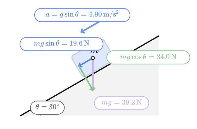
This relationship is especially clear in the interactive inclined-plane model:
a = gsinθ


4. Atwood Machines
Learning outcomes
- I can draw free-body diagrams for Atwood machines.
- I can identify tension and weight forces in pulley systems.
- I can apply Newton's Second Law to connected objects.
- I can calculate acceleration in Atwood systems.
- I can determine tension forces in pulley problems.


What Is an Atwood Machine?
An Atwood machine is a simple pulley system consisting of two masses connected by a string or rope that passes over a pulley.
The basic system contains:
- two masses, usually called m₁ and m₂
- a light string connecting the masses
- a pulley that allows the string to change direction
If the two masses are different, the heavier mass tends to move downward while the lighter mass moves upward.
Atwood machines are useful because they allow us to study the relationship between force, mass, tension, and acceleration.
The Basic Atwood Machine
Suppose:
m₂ > m₁
Then:
m₂ moves downward
and:
m₁ moves upward


Because the masses are connected by the same taut string, they move together.
In an ideal Atwood machine, both masses have the same magnitude of acceleration.
If m₂ accelerates downward at 2.0 m/s², then m₁ accelerates upward at 2.0 m/s².
Their directions are opposite, but the magnitudes are equal.
Assumptions for an Ideal Atwood Machine
Introductory Atwood-machine problems usually assume an ideal system.
This means:
- the string has negligible mass
- the string does not stretch
- the pulley has negligible mass
- the pulley has negligible friction
- the string does not slip on the pulley
Under these assumptions, the tension is the same throughout the string.
Therefore:
T₁ = T₂ = T
Real pulley systems may behave differently, but the ideal model allows us to understand the basic physics clearly.
Forces Acting on Each Mass
Each hanging mass experiences two main forces.
Weight acts downward:
Fg = mg
Tension acts upward:
T


For m₁:
↑ T
● m₁
↓ m₁g
For m₂:
↑ T
● m₂
↓ m₂g
The forces may look similar, but if the masses are different, their weights are different.
Drawing Free-Body Diagrams
It is usually best to draw a separate free-body diagram for each mass.
Suppose:
m₂ > m₁
For m₁, which accelerates upward:
↑ T
●
↓ m₁g
Because the acceleration is upward:
T > m₁g
For m₂, which accelerates downward:
↑ T
●
↓ m₂g
Because the acceleration is downward:
m₂g > T

 o7I?purpose=inline" alt="
This gives us an important relationship:
m₂g > T > m₁g
when m₂ is the heavier accelerating mass.
Applying Newton's Second Law
Newton's Second Law states:
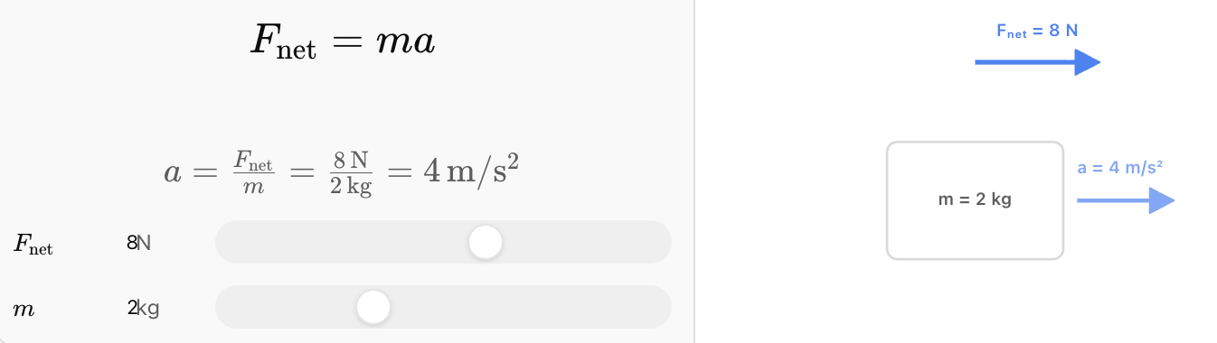
Fnet = ma


5. Elevators and Apparent Weight
Learning outcomes
- I can define apparent weight.
- I can explain why apparent weight changes during acceleration.
- I can draw free-body diagrams for elevator systems.
- I can calculate apparent weight in accelerating systems.
- I can relate apparent weight to everyday experiences.


