Heat Engines
| Site: | Young Education |
| Course: | Thermodynamics |
| Book: | Heat Engines |
| Printed by: | Guest user |
| Date: | Monday, 9 November 2026, 4:37 PM |
1. Heat Engines
Learning outcomes
- I can describe the operation of a heat engine.
- I can identify the hot and cold reservoirs.
- I can explain energy flow through an engine.
- I can calculate engine efficiency.
- I can identify examples of heat engines.
Heat Engines
A heat engine is a device that converts part of the thermal energy transferred from a high-temperature source into useful mechanical work.
All heat engines operate using the same basic energy pathway:
hot reservoir → heat engine → useful work + cold reservoir
A heat engine cannot convert all of the thermal energy it receives into useful work. Some energy must be transferred to a lower-temperature region.
This limitation is a consequence of the Second Law of Thermodynamics.


The Basic Parts of a Heat Engine
A heat engine requires three main components:
- hot reservoir
- engine or working substance
- cold reservoir
The engine operates repeatedly in a cycle, taking energy from the hot reservoir, converting some of it into work, and rejecting the remainder to the cold reservoir.
The Hot Reservoir
The hot reservoir is the high-temperature energy source.
It supplies thermal energy to the engine.
Examples include:
- burning fuel
- hot combustion gases
- steam produced in a boiler
- a nuclear reactor
- geothermal heat
- concentrated solar thermal energy
Its temperature is usually represented by:
T_h
The energy transferred from it is often represented by:
Q_h
The Cold Reservoir
The cold reservoir receives the thermal energy that the engine cannot convert into useful work.
Its temperature is represented by:
T_c
and the rejected thermal energy is:
Q_c
Possible cold reservoirs include:
- atmosphere
- cooling water
- rivers
- lakes
- oceans
- cooling towers
The cold reservoir must have:
T_c < T_h
Energy Flow Through a Heat Engine
The basic process is:
Q_h enters engine
Some becomes:
W
and the remainder leaves as:
Q_c
Therefore:
Q_h = W + Q_c
This is an application of the:
Energy is conserved.


Heat Engine Energy Equation
The energy relationship is:
Q_h = W + Q_c
Rearranging:
W = Q_h − Q_c
where:
- Q_h = thermal energy absorbed from hot reservoir
- Q_c = thermal energy rejected to cold reservoir
- W = useful work produced
All quantities can be measured in:
joules (J)
Worked Example: Energy Flow
A heat engine absorbs:
Q_h = 2000 J
and transfers:
Q_c = 1300 J
to the cold reservoir.
Find the work output.
Use:
W = Q_h − Q_c
W = 2000 − 1300
W = 700 J
Therefore, the engine produces:
700 J of useful work
What Happens to the Energy?
For the previous example:
2000 J enters
Then:
700 J → useful work
1300 J → cold reservoir
Check:
700 + 1300 = 2000
Therefore:
energy in = energy out
The First Law is satisfied.
Heat Engine Efficiency
The efficiency of a heat engine describes the fraction of input thermal energy converted into useful work.
Efficiency is represented by:
η
The equation is:
η = W/Q_h
where:
- η = efficiency
- W = useful work output
- Q_h = thermal energy supplied by the hot reservoir
Efficiency has no unit.
Percentage Efficiency
Efficiency is often expressed as a percentage:
η = (W/Q_h) × 100%
For example, if an engine receives 1000 J and produces 300 J of useful work:
η = (300/1000) × 100%
η = 30%
This means 30% of the input thermal energy became useful work.
Worked Example: Engine Efficiency
An engine receives:
Q_h = 2500 J
and produces:
W = 900 J
Efficiency:
η = W/Q_h
η = 900/2500
η = 0.36
Therefore:
η = 36%
The remaining 64% is transferred elsewhere, primarily as rejected thermal energy.
Calculating Rejected Energy
An engine receives:
5000 J
and has an efficiency of:
40%
First find useful work:
W = ηQ_h
W = 0.40 × 5000
W = 2000 J
Now:
Q_c = Q_h − W
Q_c = 5000 − 2000
Q_c = 3000 J
Therefore:
- input = 5000 J
- useful work = 2000 J
- rejected heat = 3000 J
Efficiency Using Q_h and Q_c
Since:
W = Q_h − Q_c
and:
η = W/Q_h
we can substitute:
η = (Q_h − Q_c)/Q_h
Therefore:
η = 1 − Q_c/Q_h
This provides another useful efficiency equation.
Worked Example
A heat engine absorbs:
Q_h = 4000 J
and rejects:
Q_c = 2800 J
Efficiency:
η = 1 − Q_c/Q_h
η = 1 − 2800/4000
η = 1 − 0.70
η = 0.30
Therefore:
efficiency = 30%
Why Heat Engines Need Two Reservoirs
A heat engine requires a temperature difference.
Energy enters from:
high temperature
and some energy is ultimately transferred toward:
lower temperature
This temperature difference allows the engine to produce work.
Without a temperature difference:
T_h = T_c
there would be no spontaneous net heat flow available to drive the engine.
The Second Law
The First Law tells us:
Q_h = W + Q_c
But the First Law alone does not prevent:
Q_c = 0
which would imply:
W = Q_h
and therefore:
η = 100%
The Second Law of Thermodynamics tells us why this cannot happen for a cyclic heat engine operating between finite-temperature reservoirs.
Some thermal energy must be rejected to the colder reservoir.
Therefore:
Q_c > 0
and:
η < 100%
Why 100% Efficiency Is Impossible
A heat engine cannot completely convert thermal energy from a single reservoir into work during a cycle.
Some energy must be transferred to the colder surroundings.
This is sometimes expressed through the Kelvin-Planck statement of the Second Law.
In simple terms:
no heat engine can be 100% efficient
This is a fundamental physical limitation, not merely a failure of engineering.
Reversible Heat Engines
A perfectly reversible heat engine is an idealized engine with no entropy-producing processes such as:
- friction
- turbulence
- uncontrolled expansion
- heat transfer across finite temperature differences
Such an engine would have the:
maximum possible efficiency
between its two operating temperatures.
The Carnot Engine
The Carnot engine is an ideal reversible heat engine.
Its maximum theoretical efficiency depends only on the temperatures of its hot and cold reservoirs.
The Carnot efficiency is:
η_max = 1 − T_c/T_h
where:
- T_h = hot reservoir temperature
- T_c = cold reservoir temperature
Both temperatures must be measured in:
kelvin


Worked Example: Carnot Efficiency
An ideal heat engine operates between:
T_h = 600 K
and:
T_c = 300 K
Use:
η_max = 1 − T_c/T_h
η_max = 1 − 300/600
η_max = 1 − 0.50
η_max = 0.50
Therefore:
maximum efficiency = 50%
No heat engine operating between these two temperatures can exceed 50% efficiency.
Another Carnot Example
Suppose:
T_h = 800 K
T_c = 320 K
η_max = 1 − 320/800
η_max = 1 − 0.40
η_max = 0.60
Therefore:
maximum theoretical efficiency = 60%
A real engine would have:
η_real < 60%
because real engines contain irreversible processes.
Temperature Difference and Efficiency
From:
η_max = 1 − T_c/T_h
we can see that maximum efficiency increases when:
T_h increases
or:
T_c decreases
Therefore, a larger difference between hot and cold reservoir temperatures can allow greater theoretical efficiency.
Why Kelvin Must Be Used
Suppose:
T_h = 500°C
and:
T_c = 100°C
Do not calculate:
1 − 100/500
because Carnot efficiency requires absolute temperatures.
Convert:
T_h = 500 + 273
T_h = 773 K
T_c = 100 + 273
T_c = 373 K
Then:
η_max = 1 − 373/773
η_max ≈ 0.517
or approximately:
51.7%
Real Engines
Real heat engines have efficiencies lower than the Carnot limit because they contain:
- friction
- turbulence
- heat leakage
- electrical resistance
- finite temperature differences
- finite pressure differences
- incomplete combustion
- mechanical losses
These effects are:
irreversible
and produce entropy.
Therefore:
η_real < η_max
Internal Combustion Engines
Gasoline and diesel engines are examples of:
internal combustion engines
Fuel burns inside the engine.

The combustion produces hot gases.
These gases expand and push pistons.
The piston motion turns a:
crankshaft
which can ultimately drive the wheels.
Four-Stroke Gasoline Engine
A common gasoline engine uses four strokes:
Intake
Fuel-air mixture enters the cylinder.
Compression
The piston compresses the mixture.
Power
The mixture ignites.
Hot expanding gases push the piston downward.
Exhaust
Combustion products leave the cylinder.
The cycle then repeats.
Energy Flow in a Car Engine
A simplified pathway is:
chemical energy in fuel
↓
thermal energy from combustion
↓
expanding gases
↓
mechanical work on pistons
↓
rotational mechanical energy
↓
vehicle motion
However, substantial energy is also transferred through:
- hot exhaust
- engine cooling
- friction
- sound
Therefore only part of the fuel's energy becomes useful mechanical work.
Diesel Engines
Diesel engines are also internal combustion heat engines.
Unlike conventional gasoline engines, they ignite fuel primarily through:
high compression and resulting high temperature
rather than a spark plug.
Diesel engines are widely used in:
- trucks
- buses
- ships
- generators
- heavy machinery
Steam Engines
A steam engine is an example of an:
external combustion heat engine
Fuel burns outside the engine's working cylinder.
Thermal energy heats water to produce steam.


The steam expands and performs mechanical work.
Historically, steam engines were central to:
the Industrial Revolution
Steam Turbines
Modern thermal power stations generally use:
steam turbines
rather than traditional piston steam engines.
Water is heated to produce high-pressure steam.
The steam flows through turbine blades, causing the turbine to rotate.
The turbine drives an:
electrical generator
Thermal Power Stations
A simplified power-station energy pathway is:
fuel or nuclear energy
↓
thermal energy
↓
steam
↓
turbine rotation
↓
generator
↓
electrical energy


The steam must eventually release energy to a colder reservoir.
This commonly occurs in a:
condenser
The Condenser
After passing through a turbine, steam enters a condenser.
The condenser removes thermal energy from the steam.
The steam:
condenses back into liquid water
The water can then return to the boiler.
The condenser therefore helps establish the engine's:
cold side
Cooling Towers
Cooling towers are often associated with thermal power stations.
They help transfer waste thermal energy to the atmosphere.
The large white clouds commonly visible above cooling towers are mainly:
condensed water droplets
rather than smoke.
Cooling systems are necessary partly because a heat engine must reject thermal energy to a colder reservoir.
Fossil-Fuel Power Stations
In a fossil-fuel power station:
chemical energy → thermal energy → mechanical energy → electrical energy
Coal, natural gas or another fuel supplies the original energy.
Combustion provides the high-temperature reservoir.
Cooling systems provide the low-temperature reservoir.
Nuclear Power Stations
A nuclear power station is also based on a heat-engine cycle.
The major difference is the source of thermal energy.
Instead of combustion:
nuclear fission
produces the energy.
That energy is used to produce steam and operate turbines.
Therefore:
nuclear reactor → heat source
steam turbine → heat engine
cooling system → cold reservoir
Gas Turbines
A gas turbine is another type of heat engine.
Air is compressed.
Fuel is burned.
The resulting hot gases expand through turbine blades.
Part of the turbine's output drives the compressor, while the remainder can provide useful mechanical or electrical power.
Gas turbines are used in:
- power stations
- aircraft
- ships
Jet Engines
Jet engines are heat engines.
A simplified sequence is:
air intake → compression → combustion → expansion → exhaust


Fuel combustion produces high-temperature gases.
These gases expand and ultimately produce thrust.
Jet engines demonstrate the conversion:
chemical energy → thermal energy → mechanical energy
Combined-Cycle Power Plants
A gas turbine produces extremely hot exhaust gases.
Instead of immediately releasing this energy, a combined-cycle power plant uses the hot exhaust to generate steam.
The steam then powers a second turbine.
Therefore:
gas turbine + steam turbine
extract more useful energy from the same fuel.
This improves overall efficiency.
Heat Engines in Nature
Not every heat engine needs to be a manufactured piston or turbine.
Any system that converts part of an energy flow driven by temperature differences into mechanical work can have heat-engine-like characteristics.
Atmospheric circulation, for example, is driven partly by unequal solar heating.
Temperature differences help produce:
- winds
- convection
- storms
The Earth's atmosphere can therefore be studied using thermodynamic concepts related to heat engines.
Human Body: Not a Simple Heat Engine
The human body converts chemical energy into mechanical work and thermal energy.
However, it is not accurately modeled as a conventional heat engine operating between hot and cold reservoirs.
Muscles obtain useful work primarily through:
chemical free-energy transformations
rather than by operating a thermal cycle between two temperatures.
This distinction is important when identifying genuine heat engines.
Heat Engine vs Electric Motor
An electric motor is not normally classified as a heat engine.
An electric motor converts:
electrical energy → mechanical energy
A heat engine converts energy supplied through a high-temperature thermal process into:
mechanical work
Examples of heat engines include:
- gasoline engine
- diesel engine
- steam engine
- steam turbine
- gas turbine
- jet engine
Heat Engine vs Refrigerator
A heat engine and refrigerator are related but operate differently.
Heat engine
Natural heat flow helps produce work:
hot → engine → cold
with:
work output
Refrigerator
Work is supplied to move thermal energy against its spontaneous direction:
cold → hot
with:
work input
Comparing the Two
| Heat Engine | Refrigerator |
|---|---|
| Produces work | Requires work |
| Receives heat from hot reservoir | Removes heat from cold reservoir |
| Rejects heat to cold reservoir | Rejects heat to hot reservoir |
| Converts some thermal energy to work | Uses work to transfer thermal energy |
| Example: car engine | Example: refrigerator |
Efficiency and Energy Conservation
Suppose an engine is:
35% efficient
This does not mean 65% of the energy disappears.
It means:
35% → useful work
and approximately:
65% → other energy transfers
such as rejected thermal energy.
Energy is always conserved.
Useful vs Rejected Energy
Imagine:
Q_h = 10,000 J
and:
η = 30%
Then:
W = 0.30 × 10,000
W = 3000 J
Therefore:
Q_c = 10,000 − 3000
Q_c = 7000 J
Energy accounting:
10,000 J = 3000 J + 7000 J
Nothing has disappeared.
Efficiency Cannot Exceed 1
Because:
η = W/Q_h
and:
W < Q_h
then:
η < 1
or:
η < 100%
If a calculation gives:
η > 100%
there must be an error in:
- calculation
- measurements
- interpretation of the energy transfers
Improving Engine Efficiency
Engineers improve real heat engines by reducing unnecessary irreversibility.
Strategies include:
- reducing friction
- improving lubrication
- improving combustion
- reducing heat leakage
- recovering exhaust energy
- improving turbine design
- reducing turbulence
- operating at higher hot-reservoir temperatures where materials permit
- improving cooling systems
- using combined cycles
However:
no engineering improvement can violate the Second Law
Waste Heat Recovery
Many engines release hot exhaust.
Instead of simply allowing this energy to enter the environment, some systems use:
waste heat recovery
For example:
hot exhaust → heat exchanger → additional useful energy
Combined-cycle power plants use this principle.
Recovering waste heat improves overall efficiency but still cannot produce 100% conversion.
Why Power Stations Need Cooling
A thermal power station cannot simply convert all boiler energy into electricity.
Some energy must be rejected to a colder reservoir.
Cooling systems provide this function.
Possible cold reservoirs include:
- cooling towers
- rivers
- lakes
- oceans
- atmospheric air
This requirement comes directly from the Second Law.
Heat Engines and Entropy
Heat engines operate because energy moves from:
higher temperature → lower temperature
The engine intercepts part of this energy flow and converts some of it into work.
However, entropy considerations require some energy to continue toward the cold reservoir.
Therefore heat-engine operation connects:
- First Law
- Second Law
- entropy
- temperature
- energy conservation
- efficiency
First Law and Heat Engines
The First Law gives:
Q_h = W + Q_c
It tells us:
energy is conserved
Second Law and Heat Engines
The Second Law tells us:
Q_c cannot simply be eliminated
for a cyclic heat engine operating between finite-temperature reservoirs.
Therefore:
η < 100%
Together the laws explain both:
where the energy goes
and:
why there is a limit to how much becomes useful work
Worked Example: Complete Engine Problem
A heat engine receives:
Q_h = 6000 J
and rejects:
Q_c = 3900 J
Find the work.
W = Q_h − Q_c
W = 6000 − 3900
W = 2100 J
Find the efficiency.
η = W/Q_h
η = 2100/6000
η = 0.35
η = 35%
Therefore:
- input energy = 6000 J
- work output = 2100 J
- rejected energy = 3900 J
- efficiency = 35%
Worked Example: Finding Input Energy
An engine is:
25% efficient
and produces:
500 J
of work.
Use:
η = W/Q_h
Rearrange:
Q_h = W/η
Q_h = 500/0.25
Q_h = 2000 J
Therefore the engine must absorb:
2000 J
from the hot reservoir.
Worked Example: Finding Rejected Energy
From the previous example:
Q_h = 2000 J
W = 500 J
Use:
Q_c = Q_h − W
Q_c = 2000 − 500
Q_c = 1500 J
Therefore 1500 J is transferred to the cold reservoir.
Worked Example: Comparing Engines
Engine A:
Q_h = 5000 J
W = 1500 J
η_A = 1500/5000
η_A = 30%
Engine B:
Q_h = 4000 J
W = 1600 J
η_B = 1600/4000
η_B = 40%
Therefore:
Engine B is more efficient
even though it receives less total energy.
Efficiency compares the fraction converted into useful work.
Worked Example: Real vs Maximum Efficiency
A real engine operates between:
T_h = 900 K
and:
T_c = 300 K
Maximum theoretical efficiency:
η_max = 1 − 300/900
η_max = 1 − 0.333
η_max ≈ 66.7%
Suppose the actual engine is:
40% efficient
This is physically reasonable because:
40% < 66.7%
If someone claimed the engine were 75% efficient, that would exceed the Carnot limit and would therefore be impossible between those reservoir temperatures.
Common Mistakes
Mistake: Saying a heat engine converts all heat into work.
Some energy must be rejected to a cold reservoir.
Mistake: Saying rejected energy disappears.
Energy is conserved and transferred to the surroundings.
Mistake: Confusing Q_h and Q_c.
Q_h enters from the hot reservoir; Q_c leaves toward the cold reservoir.
Mistake: Using Q_c as the input in η = W/Q_h.
Efficiency compares useful work with energy received from the hot reservoir.
Mistake: Forgetting to convert decimal efficiency to a percentage.
0.35 = 35%.
Mistake: Writing 35% as 35 in calculations.
Use 0.35.
Mistake: Saying a reversible engine is 100% efficient.
It has the maximum possible efficiency between its reservoir temperatures, not necessarily 100%.
Mistake: Using Celsius in η_max = 1 − T_c/T_h.
Use kelvin.
Mistake: Assuming an electric motor is a heat engine.
An electric motor primarily converts electrical energy directly into mechanical work.
Mistake: Saying power-station cooling towers are simply wasting energy because of poor engineering.
Real systems have avoidable losses, but the Second Law also imposes a fundamental requirement to reject thermal energy.
Key Terms
Heat engine — device operating cyclically that converts part of an energy transfer from a high-temperature source into useful work while rejecting energy to a colder reservoir.
Hot reservoir — high-temperature source supplying thermal energy to an engine.
Cold reservoir — lower-temperature region receiving rejected thermal energy.
Working substance — material, such as gas or steam, that undergoes thermodynamic changes inside an engine.
Q_h — thermal energy absorbed from the hot reservoir.
Q_c — thermal energy rejected to the cold reservoir.
Work (W) — useful mechanical energy transferred by the engine.
Efficiency (η) — fraction of input thermal energy converted into useful work.
Carnot engine — ideal reversible heat engine used to establish the maximum theoretical efficiency.
Carnot efficiency — maximum theoretical efficiency between two temperatures: η_max = 1 − T_c/T_h.
Internal combustion engine — engine in which fuel burns within the engine itself.
External combustion engine — engine in which heating occurs outside the working cylinder or turbine system.
Steam turbine — device in which expanding steam produces rotational mechanical work.
Gas turbine — heat engine using expanding hot gases to rotate turbine blades.
Condenser — component that removes thermal energy from vapor, causing it to condense.
Waste heat — thermal energy transferred away rather than converted into the desired useful output.
Combined-cycle power plant — plant that uses more than one thermodynamic cycle to recover additional useful energy.
Key Takeaways
- A heat engine converts part of an energy flow from a high-temperature source into useful work.
- Every heat engine requires a hot reservoir and a colder reservoir.
- Energy from the hot reservoir is represented by Q_h.
- Rejected energy is represented by Q_c.
- Useful work is represented by W.
- Energy conservation gives Q_h = W + Q_c.
- Therefore W = Q_h − Q_c.
- Heat-engine efficiency is η = W/Q_h.
- Percentage efficiency is η = (W/Q_h) × 100%.
- Efficiency can also be written as η = 1 − Q_c/Q_h.
- A heat engine cannot convert all its input thermal energy into work.
- Some energy must be rejected to a colder reservoir.
- Therefore no cyclic heat engine operating between finite-temperature reservoirs can be 100% efficient.
- The First Law explains energy conservation within the engine.
- The Second Law explains the fundamental efficiency limit.
- A reversible heat engine provides the maximum possible efficiency between two temperatures.
- The Carnot efficiency is η_max = 1 − T_c/T_h.
- Carnot temperatures must be measured in kelvin.
- Increasing T_h or decreasing T_c can increase the maximum theoretical efficiency.
- Real engines operate below the Carnot limit because of irreversibility.
- Friction, turbulence, heat leakage and finite temperature differences reduce real engine efficiency.
- Internal combustion engines include gasoline and diesel engines.
- Steam engines and steam turbines are examples of external-heating heat-engine systems.
- Gas turbines and jet engines are also heat engines.
- Thermal power stations use heat engines to convert thermal energy into mechanical and then electrical energy.
- Nuclear power plants also operate thermal heat-engine cycles; nuclear fission supplies the thermal energy.
- Cooling systems are essential because heat engines must reject energy to a colder reservoir.
- Combined-cycle systems improve efficiency by recovering energy that would otherwise leave in hot exhaust.
- An electric motor is not normally classified as a heat engine because its primary conversion is electrical energy to mechanical energy.
- Energy rejected by an engine is not destroyed; it is transferred to the surroundings.
- Heat-engine theory provides a practical connection between energy conservation, entropy, the Second Law and engineering efficiency.
Check Your Understanding
- Define a heat engine.
- Identify the three main parts of a basic heat-engine system.
- What is the role of the hot reservoir?
- What is the role of the cold reservoir?
- What do Q_h, Q_c and W represent?
- Write the energy-conservation equation for a heat engine.
- An engine absorbs 3000 J and rejects 1900 J. Calculate its work output.
- Write the equation for heat-engine efficiency.
- An engine absorbs 5000 J and produces 1750 J of work. Calculate its efficiency.
- An engine is 30% efficient and receives 8000 J. Calculate its useful work output.
- For the engine in Question 10, calculate the energy rejected to the cold reservoir.
- Explain why a heat engine cannot be 100% efficient.
- What is a Carnot engine?
- Write the equation for maximum Carnot efficiency.
- Why must temperatures in the Carnot equation be measured in kelvin?
- An ideal engine operates between 750 K and 300 K. Calculate its maximum theoretical efficiency.
- Identify three examples of real heat engines.
- Describe the main energy transformations occurring in a thermal power station.
- Explain why thermal power stations require cooling systems.
- Explain how the First and Second Laws of Thermodynamics together determine the operation and limitations of a heat engine.
2. The Carnot Cycle
Learning outcomes
- I can describe the Carnot cycle.
- I can explain why it represents maximum efficiency.
- I can identify each stage of the cycle.
- I can compare real engines with Carnot engines.
- I can calculate Carnot efficiency.
The Carnot Cycle
The Carnot cycle is an idealized thermodynamic cycle that describes the most efficient possible heat engine operating between two temperatures.
It was developed by French physicist Sadi Carnot in the 19th century.
A Carnot engine operates between:
- a hot reservoir at temperature T_h
- a cold reservoir at temperature T_c
and converts some of the thermal energy received from the hot reservoir into useful work.
Its importance comes from a fundamental result:
No heat engine operating between the same two temperatures can be more efficient than a Carnot engine.

Why the Carnot Cycle Matters
Real engines contain unavoidable sources of irreversibility such as:
- friction
- turbulence
- electrical resistance
- heat transfer across finite temperature differences
- rapid expansion and compression
- combustion
The Carnot cycle assumes that all processes are:
perfectly reversible
Therefore, it produces no entropy through irreversibility.
This makes it an ideal benchmark for determining:
the maximum possible efficiency of a heat engine
The Carnot Engine
A Carnot engine is an ideal heat engine containing a working substance, usually modeled as an ideal gas.
During one complete cycle, the gas:
- expands isothermally
- expands adiabatically
- compresses isothermally
- compresses adiabatically
After the fourth stage, the gas returns to:
its original thermodynamic state
The cycle can then repeat.
The Four Stages
The Carnot cycle consists of:
isothermal expansion
↓
adiabatic expansion
↓
isothermal compression
↓
adiabatic compression
↓
original state
Two processes occur at constant temperature.
Two processes occur without heat transfer.
Isothermal Processes
An isothermal process occurs at:
constant temperature
Therefore:
ΔT = 0
For an ideal gas, internal energy depends only on temperature.
So during an isothermal process:
ΔU = 0
From the First Law:
ΔU = Q − W
therefore:
Q = W
during an ideal-gas isothermal expansion.
Adiabatic Processes
An adiabatic process occurs with:
no heat transfer
Therefore:
Q = 0
From:
ΔU = Q − W
we obtain:
ΔU = −W
during expansion.
Thus the gas performs work using its internal energy and its temperature decreases.
During adiabatic compression, work is done on the gas and its temperature increases.
Stage 1: Isothermal Expansion
The gas begins in contact with the:
hot reservoir at T_h
It expands slowly while remaining at constant temperature.


During this stage:
- heat Q_h enters the gas
- gas expands
- gas performs work
- temperature remains T_h
- internal energy remains constant for an ideal gas
Energy relationship:
Q_h = W
for this stage.
The thermal energy entering the gas is converted into work while the temperature remains constant.
Why Temperature Remains Constant
As the gas expands, it performs work.
Normally, this would reduce its internal energy and temperature.
However, the hot reservoir continuously supplies energy.
Therefore:
energy entering as heat = energy leaving as work
and:
ΔU = 0
So the temperature remains constant.
Stage 2: Adiabatic Expansion
The gas is now thermally isolated.
It continues expanding.
During this stage:
Q = 0


The gas performs work on the surroundings.
Since no heat enters:
internal energy decreases
and therefore:
temperature decreases
The temperature falls from:
T_h → T_c
Energy During Adiabatic Expansion
Since:
Q = 0
the First Law becomes:
ΔU = −W
Because the gas performs positive work:
W > 0
therefore:
ΔU < 0
The gas loses internal energy and cools.
Stage 3: Isothermal Compression
The gas is placed in thermal contact with the:
cold reservoir at T_c
The surroundings slowly compress the gas.


During this stage:
- work is done on the gas
- gas volume decreases
- thermal energy Q_c leaves the gas
- temperature remains constant at T_c
For an ideal gas:
ΔU = 0
Therefore, the work done on the gas is transferred as heat to the cold reservoir.
Why Heat Leaves During Compression
Compression tends to increase the gas's internal energy and temperature.
However, the gas must remain at:
T_c
Therefore the energy supplied by compression is transferred to the cold reservoir.
The gas remains at constant temperature.
Stage 4: Adiabatic Compression
The gas is thermally isolated again.
The surroundings continue compressing it.
During this stage:
Q = 0


Work is done on the gas.
Its internal energy increases.
Therefore its temperature rises:
T_c → T_h
At the end of the process, the gas returns to its original state.
The cycle is complete.
The Complete Carnot Cycle
The four stages can be summarized as:
| Stage | Process | Heat Transfer | Temperature Change |
|---|---|---|---|
| 1 | Isothermal expansion | Q_h enters | T = T_h |
| 2 | Adiabatic expansion | Q = 0 | T_h → T_c |
| 3 | Isothermal compression | Q_c leaves | T = T_c |
| 4 | Adiabatic compression | Q = 0 | T_c → T_h |
The working gas then returns to its initial state.
Energy Flow Through the Carnot Engine
During the cycle:
hot reservoir
↓
Q_h
↓
Carnot engine
↙︎ ↘︎
W Q_c
↓
cold reservoir
Energy conservation requires:
Q_h = W + Q_c
Therefore:
W = Q_h − Q_c
The P–V Diagram
The Carnot cycle is often shown on a:
pressure-volume (P–V) diagram


The cycle forms a closed loop.
The two isothermal curves correspond to:
T_h
and:
T_c
The two adiabatic curves connect them.
Area Under a P–V Curve
For expansion or compression:
W = area under the P–V curve
During expansion:
work is done by the gas
During compression:
work is done on the gas
For a complete Carnot cycle:
net work = area enclosed by the cycle
This is an important graphical interpretation.
Why the Cycle Produces Net Work
During the high-temperature expansion, the gas performs relatively large work.
During the lower-temperature compression, less work must be supplied to compress it.
Therefore:
work during expansion > work required for compression
The difference becomes:
net useful work
Heat Engine Efficiency
Efficiency is:
η = W/Q_h
Since:
W = Q_h − Q_c
then:
η = (Q_h − Q_c)/Q_h
Therefore:
η = 1 − Q_c/Q_h
This equation applies to heat-engine efficiency in terms of heat transfers.
Carnot Efficiency
For a reversible Carnot engine:
Q_c/Q_h = T_c/T_h
Therefore:
η_Carnot = 1 − T_c/T_h
where:
- η_Carnot = maximum theoretical efficiency
- T_c = cold reservoir temperature
- T_h = hot reservoir temperature
Temperatures must be measured in:
kelvin
Worked Example: Carnot Efficiency
A Carnot engine operates between:
T_h = 600 K
and:
T_c = 300 K
Use:
η_Carnot = 1 − T_c/T_h
η = 1 − 300/600
η = 1 − 0.50
η = 0.50
Therefore:
η = 50%
The maximum possible efficiency is:
50%
Worked Example: Higher Hot Temperature
Suppose:
T_h = 900 K
T_c = 300 K
η = 1 − 300/900
η = 1 − 0.333
η ≈ 0.667
Therefore:
η ≈ 66.7%
Increasing the hot-reservoir temperature increased the maximum possible efficiency.
Worked Example: Lower Cold Temperature
Suppose:
T_h = 600 K
T_c = 200 K
η = 1 − 200/600
η = 1 − 0.333
η ≈ 66.7%
Lowering the cold-reservoir temperature also increases maximum efficiency.
Temperature Difference and Efficiency
From:
η_Carnot = 1 − T_c/T_h
we can see:
Increasing T_h tends to increase efficiency.
Decreasing T_c tends to increase efficiency.
Therefore:
larger temperature difference → greater possible efficiency
However, the ratio T_c/T_h is what directly determines Carnot efficiency.
Why Kelvin Must Be Used
Suppose:
T_h = 400°C
and:
T_c = 100°C
First convert:
T_h = 400 + 273
T_h = 673 K
T_c = 100 + 273
T_c = 373 K
Now:
η = 1 − 373/673
η ≈ 1 − 0.554
η ≈ 0.446
Therefore:
η ≈ 44.6%
Using Celsius directly would give an incorrect result.
Finding the Cold-Reservoir Temperature
Suppose a Carnot engine has:
η = 60%
and:
T_h = 750 K
Use:
η = 1 − T_c/T_h
0.60 = 1 − T_c/750
T_c/750 = 0.40
T_c = 0.40 × 750
T_c = 300 K
Finding the Hot-Reservoir Temperature
Suppose:
η = 40%
and:
T_c = 360 K
Use:
0.40 = 1 − 360/T_h
360/T_h = 0.60
T_h = 360/0.60
T_h = 600 K
Calculating Work
Suppose a Carnot engine:
- receives Q_h = 5000 J
- operates at η = 60%
Use:
η = W/Q_h
Therefore:
W = ηQ_h
W = 0.60 × 5000
W = 3000 J
The engine produces:
3000 J of work
Calculating Rejected Heat
From:
Q_h = W + Q_c
we have:
Q_c = Q_h − W
Q_c = 5000 − 3000
Q_c = 2000 J
Therefore:
- Q_h = 5000 J
- W = 3000 J
- Q_c = 2000 J
Checking with Reservoir Temperatures
Suppose:
T_h = 750 K
T_c = 300 K
Then:
Q_c/Q_h = T_c/T_h
Q_c/5000 = 300/750
Q_c/5000 = 0.40
Q_c = 2000 J
This agrees with our previous calculation.
Entropy During the Carnot Cycle
The Carnot cycle is completely reversible.
During isothermal expansion at T_h:
ΔS_hot = −Q_h/T_h
The working substance gains the corresponding entropy.
During isothermal compression at T_c, entropy is transferred to the cold reservoir.
For the complete reversible cycle:
ΔS_total = 0
No entropy is produced.
The Working Substance Returns to Its Starting State
Entropy is a:
state function
After one complete cycle, the working substance returns to exactly the same state.
Therefore:
ΔS_working substance = 0
over the complete cycle.
Similarly:
ΔU_cycle = 0
because internal energy is also a state function.
This does not mean no energy has been transferred.
The engine has:
- absorbed Q_h
- rejected Q_c
- produced W
Why the Carnot Engine Has Maximum Efficiency
Any real source of irreversibility produces entropy.
Examples include:
- friction
- turbulence
- heat transfer across finite temperature differences
- rapid expansion
- rapid compression
- electrical resistance
Entropy production reduces the maximum amount of energy that can be converted into useful work.
The Carnot engine avoids all these idealized losses.
Therefore:
no engine between the same T_h and T_c can be more efficient
Carnot's Theorem
Carnot's theorem states that:
No heat engine operating between two reservoirs can be more efficient than a reversible engine operating between those same reservoirs.
It also implies that:
all reversible engines operating between the same two temperatures have the same efficiency
regardless of their particular design or working substance.
The Working Substance Does Not Determine Maximum Efficiency
Imagine two ideal reversible engines.
Engine A uses:
helium
Engine B uses:
another ideal gas
If both operate between:
T_h = 700 K
and:
T_c = 350 K
then both have:
η = 1 − 350/700
η = 50%
Their maximum efficiency is determined by reservoir temperatures, not by the choice of working substance.
Real Engines
Real engines cannot follow the Carnot cycle perfectly.
They contain:
- friction
- finite temperature differences
- rapid gas flow
- turbulence
- combustion
- heat leakage
- mechanical resistance
Therefore:
real engines are irreversible
and:
η_real < η_Carnot
Comparing Carnot and Real Engines
| Carnot Engine | Real Engine |
|---|---|
| Idealized | Physical |
| Completely reversible | Irreversible |
| No friction | Friction present |
| No turbulence | Turbulence may occur |
| Infinitesimal temperature differences | Finite temperature differences |
| Extremely slow processes | Must operate at practical rates |
| No entropy production | Produces entropy |
| Maximum possible efficiency | Lower efficiency |
Example: Real vs Carnot Efficiency
A real engine operates between:
T_h = 800 K
and:
T_c = 300 K
Carnot limit:
η_Carnot = 1 − 300/800
η_Carnot = 1 − 0.375
η_Carnot = 62.5%
Suppose the real engine operates at:
40% efficiency
This is possible because:
40% < 62.5%
But an engine claiming:
70% efficiency
between the same temperatures would be impossible because:
70% > 62.5%
Why Real Engines Cannot Be Carnot Engines
A perfectly reversible Carnot process must proceed through infinitesimally small differences in:
- temperature
- pressure
This means the processes must occur:
extremely slowly
But a practical engine must produce:
useful power
Power is:
P = W/t
If an engine took an infinitely long time to complete each cycle:
t → ∞
then its practical power output would approach:
P → 0
Thus perfect Carnot operation is not useful as a practical engine.
Efficiency vs Power
This creates an important engineering trade-off.
To approach maximum reversible efficiency:
operate increasingly slowly
But to produce useful power:
operate at a finite rate
Real engineers therefore balance:
- efficiency
- power
- cost
- size
- reliability
- materials
- operating temperature
The most efficient theoretical engine is not necessarily the most practical engine.
Carnot Cycle on a P–V Diagram
The Carnot P–V diagram contains four curves.
A → B
Isothermal expansion at T_h
Heat enters.
B → C
Adiabatic expansion
Temperature falls from T_h to T_c.
C → D
Isothermal compression at T_c
Heat leaves.
D → A
Adiabatic compression
Temperature rises from T_c to T_h.


The area enclosed by the loop represents:
net work produced per cycle
Carnot Cycle on a Temperature-Entropy Diagram
The Carnot cycle can also be represented using a:
temperature-entropy (T–S) diagram


For an ideal Carnot cycle:
- isothermal processes appear horizontally
- reversible adiabatic processes occur at constant entropy and appear vertically
The result is a rectangular cycle on an idealized T–S diagram.
Reversible Adiabatic Means Isentropic
During a reversible adiabatic process:
Q = 0
and no entropy is produced.
Therefore:
ΔS = 0
Such a process is called:
isentropic
Thus Stages 2 and 4 of the ideal Carnot cycle are:
reversible adiabatic = isentropic
The Four Stages in Energy Terms
Stage 1
Isothermal expansion
Q_h enters.
Gas performs work.
Stage 2
Adiabatic expansion
No heat transfer.
Gas performs work and cools.
Stage 3
Isothermal compression
Work is done on gas.
Q_c leaves.
Stage 4
Adiabatic compression
No heat transfer.
Work is done on gas and it warms.
Then the cycle repeats.
Why Heat Is Absorbed at T_h
During Stage 1, the working gas remains in thermal contact with the hot reservoir.
To make this transfer perfectly reversible, the temperature difference between reservoir and gas would need to be:
infinitesimally small
This allows heat transfer without entropy production in the ideal limit.
Why Heat Is Rejected at T_c
During Stage 3, the working substance is in thermal contact with the cold reservoir.
Again, the temperature difference must approach:
zero
for perfectly reversible heat transfer.
The gas releases Q_c while remaining at T_c.
Why 100% Carnot Efficiency Is Impossible
For:
η_Carnot = 1
we would require:
T_c/T_h = 0
Therefore either:
T_c = 0 K
or an unboundedly large T_h.
Neither provides a realizable finite-temperature heat engine.
Therefore:
η_Carnot < 100%
for engines operating between finite, physically realizable temperatures.
Example: Very Hot Engine
Suppose:
T_h = 1500 K
and:
T_c = 300 K
η = 1 − 300/1500
η = 1 − 0.20
η = 80%
Even with an extremely hot reservoir, the maximum theoretical efficiency is still below 100%.
A real engine would achieve less than 80%.
Engineering and High Temperatures
Increasing T_h can improve theoretical efficiency.
However, real materials place limits on operating temperatures.
At very high temperatures:
- metals weaken
- turbine blades can deform
- oxidation increases
- cooling becomes difficult
- components may melt or fail
Therefore engineers cannot simply increase T_h indefinitely.
Engineering and Low Temperatures
Lowering T_c can also increase efficiency.
However, cooling the cold reservoir itself may require:
additional energy
and environmental conditions impose limits.
Therefore practical engines cannot arbitrarily lower T_c either.
Steam Power Plants
Steam power plants do not operate on a perfect Carnot cycle.
They commonly use cycles related to the:
Rankine cycle


The system includes:
- boiler
- turbine
- condenser
- pump
The Carnot cycle remains useful because it establishes the maximum theoretical efficiency between given temperatures.
Internal Combustion Engines
Gasoline engines are commonly modeled using idealized cycles such as the:
Otto cycle
Diesel engines can be modeled using the:
Diesel cycle
Gas turbines are often modeled using the:
Brayton cycle
These are not Carnot cycles.
But Carnot efficiency still provides a fundamental upper benchmark based on operating temperatures.
Carnot Efficiency as a Benchmark
Suppose a real power plant has:
η_real = 45%
and its Carnot limit is:
η_Carnot = 60%
It may be useful to compare:
45/60 = 0.75
The real plant achieves about:
75% of the Carnot-limit efficiency
This does not mean the plant is 75% efficient overall.
Its actual efficiency remains:
45%
It means it achieves 75% of the maximum theoretical value available between those temperatures.
Worked Example: Full Carnot Problem
A Carnot engine operates between:
T_h = 1000 K
and:
T_c = 400 K
It absorbs:
Q_h = 5000 J
Find the efficiency
η = 1 − 400/1000
η = 0.60
η = 60%
Find the work output
W = ηQ_h
W = 0.60 × 5000
W = 3000 J
Find Q_c
Q_c = Q_h − W
Q_c = 5000 − 3000
Q_c = 2000 J
Therefore:
Q_h = 5000 J
W = 3000 J
Q_c = 2000 J
Worked Example: Testing an Engine Claim
An engineer claims an engine operating between:
700 K
and:
350 K
has an efficiency of:
60%
Find the Carnot limit:
η_Carnot = 1 − 350/700
η_Carnot = 0.50
η_Carnot = 50%
The claimed efficiency is:
60%
Since:
60% > 50%
the claim violates the Carnot limit.
Such an engine cannot operate as claimed between those two reservoirs.
Worked Example: Comparing Two Engines
Engine A:
T_h = 600 K
T_c = 300 K
η_A = 1 − 300/600
η_A = 50%
Engine B:
T_h = 900 K
T_c = 300 K
η_B = 1 − 300/900
η_B ≈ 66.7%
Engine B has the higher theoretical maximum efficiency because it operates with the larger temperature ratio difference.
Carnot Cycle and the Second Law
The Carnot cycle demonstrates several major consequences of the Second Law:
- heat engines require hot and cold reservoirs
- not all thermal energy can become work
- reversible processes establish maximum efficiency
- irreversible processes reduce efficiency
- entropy production reduces available useful work
- no engine can exceed the Carnot limit
The Carnot cycle therefore provides one of the clearest links between:
temperature, entropy, energy and efficiency
Common Mistakes
Mistake: Saying the Carnot engine is a real engine design.
It is an idealized thermodynamic model.
Mistake: Saying the Carnot engine is 100% efficient.
Its efficiency is η = 1 − T_c/T_h and is below 100% for finite reservoir temperatures.
Mistake: Using Celsius in the Carnot equation.
Always use kelvin.
Mistake: Confusing the hot and cold temperatures.
T_h is the higher temperature and T_c is the lower temperature.
Mistake: Saying all four stages transfer heat.
The two adiabatic stages have Q = 0.
Mistake: Saying temperature changes during the isothermal stages.
Isothermal means constant temperature.
Mistake: Saying temperature stays constant during adiabatic expansion.
The gas cools because it performs work without receiving heat.
Mistake: Saying temperature stays constant during adiabatic compression.
The gas warms because work is done on it without heat leaving.
Mistake: Saying real engines can reach Carnot efficiency if friction is reduced enough.
Perfect Carnot efficiency requires completely reversible processes, an unattainable idealization.
Mistake: Saying a larger temperature difference always means a practical engine will automatically be more efficient.
Carnot efficiency sets the theoretical limit; real efficiency also depends on design and irreversibilities.
Key Terms
Carnot cycle — ideal reversible thermodynamic cycle consisting of two isothermal and two adiabatic processes.
Carnot engine — ideal heat engine operating through a Carnot cycle.
Hot reservoir — high-temperature source supplying thermal energy Q_h.
Cold reservoir — lower-temperature region receiving Q_c.
Working substance — material undergoing expansion and compression during the cycle.
Isothermal process — process occurring at constant temperature.
Adiabatic process — process involving no heat transfer.
Isentropic process — process occurring at constant entropy; a reversible adiabatic process is isentropic.
Reversible process — ideal process producing no net entropy.
Carnot efficiency — maximum theoretical efficiency between two reservoir temperatures.
P–V diagram — graph of pressure against volume used to represent thermodynamic processes.
T–S diagram — graph of temperature against entropy.
Carnot's theorem — principle stating that no engine can exceed the efficiency of a reversible engine operating between the same temperatures.
Q_h — thermal energy absorbed from the hot reservoir.
Q_c — thermal energy rejected to the cold reservoir.
Net work (W) — useful work produced over one complete engine cycle.
Key Takeaways
- The Carnot cycle represents an ideal reversible heat-engine cycle.
- It consists of four stages.
- Stage 1 is isothermal expansion at T_h.
- Stage 2 is adiabatic expansion from T_h to T_c.
- Stage 3 is isothermal compression at T_c.
- Stage 4 is adiabatic compression from T_c to T_h.
- Heat enters only during the high-temperature isothermal expansion.
- Heat leaves during the low-temperature isothermal compression.
- No heat is transferred during either adiabatic stage.
- The working substance returns to its initial state after each complete cycle.
- The net work produced equals Q_h − Q_c.
- On a P–V diagram, the enclosed area represents the net work per cycle.
- The Carnot engine is completely reversible.
- It therefore produces no net entropy.
- Carnot efficiency is η_Carnot = 1 − T_c/T_h.
- Temperatures in the Carnot equation must be measured in kelvin.
- The Carnot efficiency depends only on the two reservoir temperatures.
- Increasing T_h increases the theoretical maximum efficiency.
- Decreasing T_c increases the theoretical maximum efficiency.
- A Carnot engine operating between finite temperatures cannot be 100% efficient.
- No real engine operating between the same temperatures can exceed Carnot efficiency.
- Real engines have lower efficiency because they contain irreversible processes.
- Friction, turbulence and finite temperature differences are important sources of irreversibility.
- Real engines must operate at finite rates to produce useful power.
- A perfectly reversible Carnot engine would operate extremely slowly and is therefore an idealization.
- Steam turbines, gasoline engines, diesel engines and gas turbines use practical cycles rather than the Carnot cycle.
- The Carnot cycle provides a benchmark against which real engines can be evaluated.
- Carnot's theorem is a fundamental consequence of the Second Law of Thermodynamics.
Check Your Understanding
- What is the Carnot cycle?
- Why is the Carnot cycle important in thermodynamics?
- Name the four stages of the Carnot cycle in order.
- What happens during isothermal expansion?
- Why does the temperature remain constant during isothermal expansion?
- What happens to the temperature during adiabatic expansion?
- Why does the gas cool during adiabatic expansion?
- What happens during isothermal compression?
- What happens during adiabatic compression?
- During which two stages is Q = 0?
- What does the area enclosed by a Carnot cycle on a P–V diagram represent?
- Write the equation for Carnot efficiency.
- Why must temperatures in the Carnot efficiency equation be measured in kelvin?
- A Carnot engine operates between 800 K and 400 K. Calculate its maximum efficiency.
- A Carnot engine operates between 900 K and 300 K and absorbs 6000 J. Calculate its work output.
- For the engine in Question 15, calculate Q_c.
- Explain why a Carnot engine cannot reach 100% efficiency.
- Why are real engines less efficient than Carnot engines operating between the same temperatures?
- Explain why a perfectly reversible Carnot engine would be impractical as a real engine.
- A real engine operating between 700 K and 350 K claims an efficiency of 55%. Use the Carnot limit to evaluate whether this claim is physically possible.
3. Refrigerators and Heat Pumps
Learning outcomes
- I can explain how refrigerators transfer thermal energy.
- I can distinguish refrigerators from heat pumps.
- I can define coefficient of performance.
- I can explain why work is required.
- I can identify household applications.


4. Real Engines
Learning outcomes
- I can describe internal combustion engines.
- I can compare gasoline and diesel engines.
- I can explain why real engines are less efficient.
- I can identify energy losses.
- I can evaluate engine performance.
Real Engines
Engines are among the most important applications of thermodynamics. They power cars, trucks, ships, aircraft, generators, agricultural machinery, and industrial equipment.
An engine converts energy from one form into another. In a typical internal combustion engine, the chemical energy stored in fuel is released through combustion. Some of this energy is converted into useful mechanical work, while the remainder is transferred to the surroundings.
Although ideal thermodynamic models help us understand the maximum possible performance of heat engines, real engines are never perfectly efficient. Friction, heat transfer, exhaust gases, incomplete combustion, and mechanical limitations all reduce the amount of useful work produced.
Understanding real engines requires knowledge of energy conservation, thermodynamic cycles, pressure, temperature, work, power, and efficiency.
In this lesson, we will investigate how internal combustion engines operate, compare gasoline and diesel engines, explain why real engines are less efficient than ideal engines, identify major energy losses, and evaluate engine performance using mathematical calculations.
What Is an Internal Combustion Engine?
An internal combustion engine (ICE) is a heat engine in which fuel burns inside the engine, producing high-temperature, high-pressure gases that perform mechanical work.
In most automotive engines, the expanding gases push a piston inside a cylinder. The piston is connected to a crankshaft, which converts the piston's back-and-forth motion into rotational motion.
This rotation can drive a vehicle's wheels or operate machinery.
Main Components
|
Component |
Function |
|---|---|
|
Cylinder |
Contains the moving piston and combustion gases |
|
Piston |
Moves as gas pressure changes |
|
Connecting rod |
Transfers force from the piston to the crankshaft |
|
Crankshaft |
Converts reciprocating motion into rotation |
|
Intake valve |
Controls the entry of air or air-fuel mixture |
|
Exhaust valve |
Allows exhaust gases to leave |
|
Spark plug |
Ignites the mixture in a typical gasoline engine |
|
Fuel injector |
Delivers fuel into the intake system or cylinder |
|
Cooling system |
Removes excess thermal energy |
|
Lubrication system |
Reduces friction and wear |
Energy Transformations
The principal energy transformations are:
Chemical energy in fuel → Thermal energy from combustion → Mechanical work
However, not all the fuel's chemical energy becomes useful work.
Some energy is transferred to:
-
Exhaust gases.
-
Engine coolant.
-
Surrounding air.
-
Frictional heating.
-
Sound and vibration.
-
Auxiliary equipment.
The law of conservation of energy requires that all energy entering the engine must be accounted for.
The Four-Stroke Engine Cycle
Most conventional car engines operate using a four-stroke cycle.
A stroke is one movement of the piston from one end of the cylinder to the other.
The four strokes are intake, compression, power, and exhaust.
1. Intake Stroke
The piston moves downward. The intake valve opens, allowing air or an air-fuel mixture to enter the cylinder.
2. Compression Stroke
The piston moves upward with the valves closed, compressing the gas. Pressure and temperature increase.
3. Power Stroke
Combustion releases energy, increasing the pressure and temperature of the gases. The expanding gases push the piston downward and perform work.
4. Exhaust Stroke
The piston moves upward, forcing combustion products out through the exhaust valve.
A complete four-stroke cycle requires two crankshaft revolutions, or 720° of rotation.
Each cylinder produces one power stroke during these two revolutions.
In a multi-cylinder engine, the power strokes are staggered to provide smoother operation.
Gasoline Engines
A gasoline engine generally operates using spark ignition.
Air and fuel are mixed, compressed, and ignited by a spark plug.
The resulting combustion increases the temperature and pressure of the gases inside the cylinder.
These gases expand and push the piston downward.
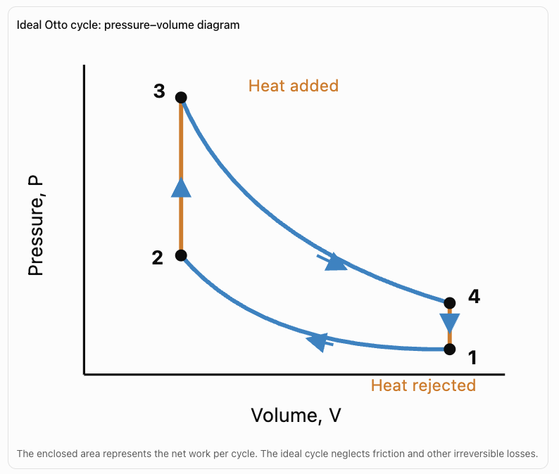
The Ideal Otto Cycle
The ideal Otto cycle is a simplified thermodynamic model commonly associated with spark-ignition engines.
It consists of four idealised processes:
-
Adiabatic, reversible (isentropic) compression.
-
Constant-volume heat addition.
-
Isentropic expansion.
-
Constant-volume heat rejection.
The ideal Otto cycle is a closed-system model. Actual engines exchange gases with their surroundings and do not follow these processes exactly.
Pressure–Volume Diagram
Otto Cycle Efficiency
For an ideal Otto cycle with a constant specific heat ratio:
η = 1 − 1/r^(γ − 1)
where:
-
η = thermal efficiency.
-
r = compression ratio.
-
γ = ratio of specific heats, Cₚ/Cᵥ.
For air near room temperature, γ is approximately 1.4. In real engines, the effective value changes with temperature and gas composition.
The compression ratio is:
r = Vₘₐₓ / Vₘᵢₙ
A higher compression ratio generally increases ideal Otto-cycle efficiency.
However, gasoline engines are limited by abnormal combustion, particularly knock, as well as temperature, pressure, and material constraints.
Worked Example 1: Otto Cycle Efficiency
An ideal Otto-cycle engine has a compression ratio of 9.
Assume γ = 1.4.
Calculate the theoretical thermal efficiency.
Solution
η = 1 − 1/r^(γ − 1)
Substitute:
η = 1 − 1/9^0.4
9^0.4 ≈ 2.408
η = 1 − 1/2.408
η ≈ 0.5847
Answer: Approximately 58.5%
This is an ideal-cycle efficiency, not the actual brake thermal efficiency of a gasoline engine.
Diesel Engines
A diesel engine generally uses compression ignition.
Unlike a typical gasoline engine, a diesel engine does not rely on a spark plug to ignite the main fuel charge.
Instead:
-
Air enters the cylinder.
-
The air is strongly compressed.
-
Compression raises its temperature.
-
Diesel fuel is injected into the hot compressed air.
-
The fuel ignites and combustion occurs.
Diesel engines commonly operate at higher compression ratios than gasoline engines.
The Ideal Diesel Cycle
The ideal Diesel cycle consists of:
-
Isentropic compression.
-
Constant-pressure heat addition.
-
Isentropic expansion.
-
Constant-volume heat rejection.
Actual diesel combustion does not occur entirely at constant pressure. The ideal Diesel cycle is a mathematical approximation.
Diesel Cycle Efficiency
For an ideal Diesel cycle with constant specific heats:
η = 1 − [1/r^(γ − 1)] × [(ρ^γ − 1)/(γ(ρ − 1))]
where:
-
r = compression ratio.
-
ρ = cutoff ratio.
-
γ = specific heat ratio.
The cutoff ratio is the volume at the end of ideal heat addition divided by the volume at its beginning.
For the same compression ratio and γ, the ideal Otto cycle has a higher efficiency than the ideal Diesel cycle when ρ > 1.
However, real diesel engines often achieve higher fuel efficiency than comparable conventional gasoline engines because they can operate with higher compression ratios and generally have lower throttling losses.
Comparing Gasoline and Diesel Engines
|
Feature |
Gasoline engine |
Diesel engine |
|---|---|---|
|
Typical ignition method |
Spark ignition |
Compression ignition |
|
Fuel |
Gasoline |
Diesel |
|
Typical compression ratio |
Approximately 8:1–14:1 |
Approximately 14:1–22:1 |
|
Idealised thermodynamic cycle |
Otto cycle |
Diesel cycle |
|
Fuel delivery |
Port or direct injection |
Usually direct injection |
|
Load control |
Often uses intake throttling |
Commonly controlled primarily by fuel quantity |
|
Typical operating speed |
Often higher |
Often lower |
|
Low-speed torque |
Varies by design |
Often strong |
|
Fuel efficiency |
Generally lower for conventional engines |
Generally higher for comparable conventional engines |
|
Emissions considerations |
CO, hydrocarbons, NOₓ, CO₂ |
NOₓ, particulates, CO₂ |
|
Common applications |
Cars, motorcycles, small engines |
Trucks, ships, generators, heavy equipment |
These are broad tendencies, not universal rules. Modern engine technologies, including turbocharging, direct injection, hybridisation, variable valve timing, and emissions aftertreatment, can significantly change performance.
Why Are Real Engines Less Efficient?
Ideal thermodynamic cycles assume simplified, reversible processes.
Real engines operate under conditions that introduce irreversible energy transfers and mechanical losses.
The main reasons for reduced efficiency include:
Friction
Moving components experience friction.
Examples include:
-
Piston rings sliding against cylinder walls.
-
Crankshaft bearings.
-
Valve mechanisms.
-
Oil pumps and other moving parts.
Some mechanical energy is converted into thermal energy through friction.
Heat Transfer to the Surroundings
Combustion gases reach high temperatures.
Energy is transferred to the cylinder walls, cylinder head, piston, coolant, and surrounding air.
This energy is generally unavailable for useful shaft work.
Exhaust Energy
Exhaust gases leave the engine at temperatures and pressures above ambient conditions.
They carry thermal energy and, in some cases, pressure energy that has not been converted into useful work.
Turbochargers can recover part of the exhaust gas energy to drive a compressor, although this does not eliminate exhaust losses.
Incomplete Combustion
Not all fuel necessarily burns completely.
Incomplete combustion can produce carbon monoxide, unburned hydrocarbons, and soot.
Some of the fuel's chemical energy remains in these products.
Pumping Losses
Engines must move air into the cylinders and exhaust gases out.
This requires work.
In throttled gasoline engines, restrictions to intake airflow can cause significant pumping losses, especially at low loads.
Auxiliary Equipment
Some useful engine output is consumed by systems such as:
-
Oil pumps.
-
Coolant pumps.
-
Alternators.
-
Cooling fans.
-
Fuel delivery equipment.
These reduce the power available at the output shaft or to the driven load.
Non-Ideal Combustion and Expansion
Real combustion takes a finite amount of time.
The heat release does not occur exactly according to ideal constant-volume or constant-pressure processes.
Other effects include:
-
Heat transfer during compression and expansion.
-
Gas leakage past piston rings.
-
Changing gas properties.
-
Irreversible flow.
-
Pressure losses.
-
Combustion occurring away from the most favourable crank angle.
These effects further reduce performance.
Energy Flow Through a Real Engine
The chemical energy supplied by fuel is distributed among useful work and several forms of energy loss.
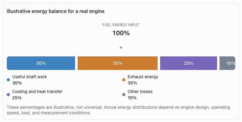
For a steady-running engine, the energy balance can be expressed approximately as:
Fuel energy input = Useful work output + Energy losses
For rates of energy transfer:
P_fuel = P_brake + P_losses
where all terms are measured in watts.
Thermal Efficiency
Thermal efficiency measures the fraction of supplied thermal or fuel energy converted into useful work.
For a real engine, brake thermal efficiency is commonly defined as:
η_b = Useful shaft power / Fuel energy input rate
Therefore:
η_b = P_b / (ṁ_f × LHV)
where:
-
η_b = brake thermal efficiency.
-
P_b = brake power output, in watts.
-
ṁ_f = fuel mass flow rate, in kg/s.
-
LHV = lower heating value of the fuel, in J/kg.
The lower heating value excludes the energy that would be recovered by condensing the water vapour in the exhaust.
Worked Example 2: Calculating Real Engine Efficiency
An engine receives fuel energy at a rate of 120 kW.
It produces 36 kW of useful shaft power.
Calculate its brake thermal efficiency.
Solution
η_b = P_b / P_fuel
η_b = 36 / 120
η_b = 0.30
Percentage efficiency:
η_b = 30%
Answer: 30%
The remaining 70% of the input energy is not converted into useful shaft power.
It leaves through exhaust, heat transfer, frictional effects, and other losses.
Work Done by Expanding Gases
When gases expand against a piston, they can perform mechanical work.
For a constant external pressure:
W = PΔV
where:
-
W = work done, in joules.
-
P = pressure, in pascals.
-
ΔV = change in volume, in cubic metres.
For variable pressure:
W = ∫ P dV
The work corresponds to the area under the pressure–volume curve for a quasistatic process.
For a complete cycle, the net work is represented by the area enclosed by the cycle on a P–V diagram.
Worked Example 3: Work During Expansion
A gas expands from 0.002 m³ to 0.006 m³ at a constant pressure of 300 kPa.
Calculate the work done.
Solution
W = PΔV
Convert pressure:
300 kPa = 300,000 Pa
Change in volume:
ΔV = 0.006 − 0.002
ΔV = 0.004 m³
Therefore:
W = 300,000 × 0.004
Answer: W = 1,200 J
The gas performs 1,200 J of work during expansion.
This calculation assumes constant pressure throughout the process.
Engine Power
Power is the rate at which work is done.
P = W/t
where:
-
P = power, in watts.
-
W = work, in joules.
-
t = time, in seconds.
For rotating machinery, power can also be calculated using:
P = τω
where:
-
τ = torque, in N·m.
-
ω = angular velocity, in rad/s.
If engine speed is measured in revolutions per minute (rpm):
ω = 2πN/60
Therefore:
P = 2πτN/60
Worked Example 4: Engine Power from Torque
An engine produces a torque of 200 N·m at 3,000 rpm.
Calculate its mechanical power output.
Solution
P = 2πτN/60
Substitute:
P = 2π(200)(3,000)/60
P = 20,000π
P ≈ 62,832 W
Convert to kilowatts:
P ≈ 62.8 kW
Answer: Approximately 62.8 kW
This is the power corresponding to the stated torque and rotational speed.
Torque and Engine Performance
Torque is a measure of the turning effect of a force.
τ = Fr
for a force acting perpendicular to a lever arm of length r.
In an engine, torque is produced by forces transmitted from the pistons through the connecting rods to the crankshaft.
Torque Versus Power
Torque and power describe different aspects of engine performance.
Torque describes rotational force.
Power describes the rate of energy transfer or work.
An engine may produce high torque at relatively low rpm but reach maximum power at a higher rpm.
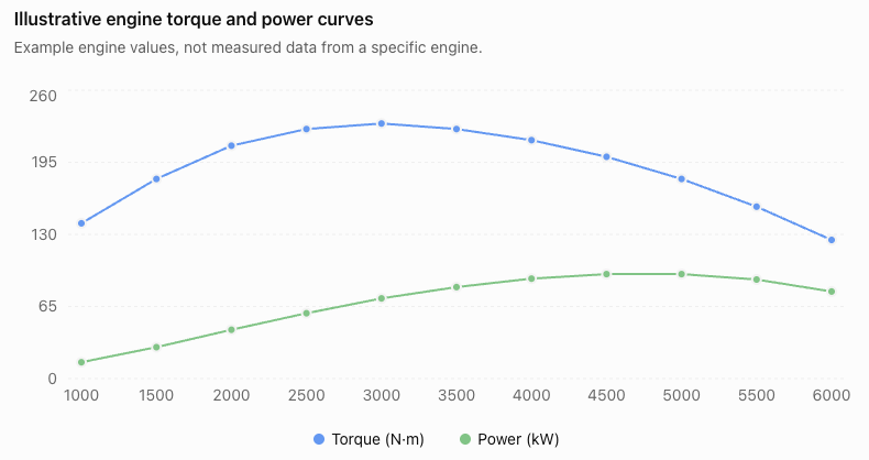
The curves illustrate that maximum torque and maximum power may occur at different engine speeds.
Because the two quantities have different units, their numerical heights should not be directly compared. Each curve should be interpreted according to its own units.
Fuel Consumption and Engine Efficiency
Fuel consumption is another important measure of engine performance.
An engine that uses less fuel to produce the same useful work is generally more fuel-efficient.
Brake Specific Fuel Consumption
Brake specific fuel consumption (BSFC) measures the mass of fuel consumed per unit of useful shaft energy produced.
BSFC = Fuel mass flow rate / Brake power
A common unit is:
g/kWh
Lower BSFC generally indicates better fuel efficiency for a given fuel.
Worked Example 5: Calculating BSFC
An engine consumes 12 kg of fuel per hour while producing 50 kW of shaft power.
Calculate BSFC.
Solution
Convert fuel consumption:
12 kg/h = 12,000 g/h
BSFC = 12,000 / 50
Answer: 240 g/kWh
This means the engine consumes 240 grams of fuel for every kilowatt-hour of shaft energy produced at this operating condition.
Worked Example 6: Calculating Efficiency from BSFC
An engine has a BSFC of 250 g/kWh.
The fuel has a lower heating value of 43 MJ/kg.
Calculate its brake thermal efficiency.
Solution
For 1 kWh of useful output:
Useful energy = 3.6 MJ
Fuel consumed:
250 g = 0.250 kg
Fuel energy supplied:
E_in = 0.250 × 43
E_in = 10.75 MJ
Efficiency:
η = 3.6 / 10.75
η ≈ 0.3349
Answer: Approximately 33.5%
This shows how fuel consumption data can be used to evaluate engine performance.
Why Efficiency Changes with Engine Speed and Load
An engine does not operate at one constant efficiency.
Efficiency changes with:
-
Engine speed.
-
Load.
-
Air-fuel ratio.
-
Compression ratio.
-
Combustion timing.
-
Engine temperature.
-
Friction.
-
Pumping losses.
-
Turbocharger operation.
-
Auxiliary power requirements.
At very low loads, fixed friction and pumping losses can represent a large proportion of the useful output.
At high loads, some engines may require changes to combustion timing or fuel mixture that reduce efficiency.
An engine's most efficient operating point is often somewhere between very low and maximum load.
Brake Thermal Efficiency Maps
Engineers use efficiency maps to compare performance across different combinations of speed and torque.
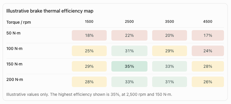
Efficiency maps help engineers choose operating conditions and design transmissions and hybrid systems.
Mechanical Efficiency
Not all power developed by the gases inside the cylinders reaches the output shaft.
Some is lost to friction and the operation of engine components.
Two useful quantities are:
Indicated power (Pᵢ): Power developed by the gases acting on the pistons.
Brake power (Pᵦ): Useful power measured at the engine output shaft.
Mechanical efficiency is:
ηₘ = Pᵦ/Pᵢ
Worked Example 7: Mechanical Efficiency
An engine develops 80 kW of indicated power.
Its measured brake power is 68 kW.
Calculate its mechanical efficiency.
Solution
ηₘ = Pᵦ/Pᵢ
ηₘ = 68/80
ηₘ = 0.85
Answer: 85%
The difference between indicated and brake power is:
80 − 68 = 12 kW
This is the friction and mechanical-loss power under the stated measurement convention.
Comparing Ideal and Real Engines
|
Characteristic |
Ideal engine model |
Real engine |
|---|---|---|
|
Friction |
Neglected |
Present |
|
Heat transfer |
Simplified |
Occurs through engine components |
|
Combustion |
Idealised heat addition |
Finite-rate chemical reaction |
|
Gas properties |
Often treated as constant |
Vary with temperature and composition |
|
Leakage |
Neglected |
May occur |
|
Pumping losses |
Often neglected |
Present |
|
Exhaust energy |
Idealised heat rejection |
Significant energy carried by exhaust |
|
Efficiency |
Higher theoretical value |
Lower measured value |
|
Performance |
Determined by model assumptions |
Depends on speed, load, design, and operating conditions |
Ideal models remain valuable because they establish reference behaviour and help engineers understand how changes in compression ratio, temperature, and other parameters affect performance.
The Second Law of Thermodynamics and Engine Efficiency
The first law of thermodynamics states that energy is conserved.
However, energy conservation alone does not explain why engines cannot convert all fuel energy into useful work.
The second law of thermodynamics introduces limits on energy conversion.
A cyclic heat engine operating between a hot reservoir and a cold reservoir cannot convert all the heat it receives into work.
For an ideal reversible engine operating between two constant-temperature reservoirs, the maximum thermal efficiency is the Carnot efficiency:
η_Carnot = 1 − T_c/T_h
where:
-
T_c = cold reservoir temperature in kelvin.
-
T_h = hot reservoir temperature in kelvin.
This expression is a theoretical limit for the specified reservoirs. A real internal combustion engine does not operate between two constant-temperature reservoirs, so substituting a single combustion temperature into this formula does not directly predict its actual efficiency.
Worked Example 8: Carnot Efficiency
A theoretical heat engine operates between:
T_h = 900 K
T_c = 300 K
Calculate the maximum efficiency.
Solution
η = 1 − T_c/T_h
η = 1 − 300/900
η = 1 − 1/3
η = 2/3
Answer: Approximately 66.7%
A real engine operating under comparable thermal limits would achieve a lower efficiency because of irreversibilities and other losses.
Environmental Performance
Engine performance is not measured only by power and efficiency.
Environmental effects are also important.
Carbon Dioxide
Burning hydrocarbon fuels produces carbon dioxide.
CO₂ is a greenhouse gas that contributes to climate change.
Reducing fuel consumption generally reduces CO₂ emissions for a given fuel and operating task.
Nitrogen Oxides
High combustion temperatures can promote the formation of nitrogen oxides (NOₓ).
These pollutants contribute to air-quality problems.
Particulate Matter
Diesel engines, particularly without effective emissions controls, can produce particulate matter.
Modern diesel particulate filters substantially reduce particulate emissions.
Carbon Monoxide and Unburned Hydrocarbons
Incomplete combustion can produce carbon monoxide and unburned hydrocarbons.
Catalytic converters and other emissions-control systems help reduce these pollutants.
Efficiency Versus Emissions
Improving thermal efficiency does not automatically minimise every pollutant.
For example, combustion conditions that improve efficiency may also increase NOₓ formation.
Engine design therefore involves balancing:
-
Efficiency.
-
Power.
-
Fuel consumption.
-
Reliability.
-
Manufacturing cost.
-
Emissions.
-
Noise and vibration.
Technologies That Improve Engine Efficiency
Turbocharging
A turbocharger uses energy from exhaust gases to drive a compressor, increasing the mass of air entering the cylinders and enabling greater power from a given engine displacement.
Direct Fuel Injection
Precisely controlled injection can improve fuel delivery and combustion under suitable operating conditions.
Variable Valve Timing
Adjusting valve operation can improve breathing, reduce pumping losses, and optimise performance across different speeds and loads.
Hybrid Powertrains
Combining an internal combustion engine with an electric motor can reduce inefficient engine operation and recover some vehicle kinetic energy during braking.
Common Mistakes
Mistake 1: Assuming engines convert all fuel energy into useful work
Real engines lose energy through exhaust gases, cooling, friction, and other processes.
Mistake 2: Confusing gasoline and diesel ignition methods
Typical gasoline engines use spark ignition.
Diesel engines use compression ignition.
Mistake 3: Assuming diesel engines are always more efficient
Diesel engines often achieve higher efficiency, but actual performance depends on engine design and operating conditions.
Mistake 4: Confusing torque with power
Torque measures rotational turning effect.
Power measures the rate of doing work.
Mistake 5: Assuming maximum power occurs at maximum efficiency
An engine may produce maximum power at a different speed and load from its most efficient operating point.
Mistake 6: Using Celsius temperatures in the Carnot efficiency formula
Absolute temperatures in kelvin must be used.
Mistake 7: Confusing ideal-cycle efficiency with brake thermal efficiency
Ideal-cycle efficiency describes a simplified thermodynamic model.
Brake thermal efficiency measures useful shaft output relative to fuel energy input.
Mistake 8: Assuming a higher compression ratio always produces better real-world performance
Higher compression ratios can improve theoretical efficiency but may introduce combustion, mechanical, and thermal limitations.
Mistake 9: Ignoring units
Power, energy, torque, and fuel consumption are different quantities.
Always check unit consistency before calculating.
Mistake 10: Assuming low fuel consumption automatically means low emissions of every pollutant
CO₂ emissions and local air pollutants depend on different factors, including combustion conditions and emissions-control technology.
Key Terms
-
Internal combustion engine: An engine in which fuel burns inside the engine to produce mechanical work.
-
Heat engine: A device that converts part of a thermal energy input into work while rejecting energy to its surroundings.
-
Piston: A moving component that transfers force from expanding gases.
-
Cylinder: The chamber in which the piston moves.
-
Crankshaft: A rotating shaft that converts reciprocating piston motion into rotation.
-
Four-stroke cycle: A sequence of intake, compression, power, and exhaust strokes.
-
Spark ignition: Ignition initiated by a spark plug.
-
Compression ignition: Ignition caused by fuel entering sufficiently hot compressed air.
-
Otto cycle: An idealised thermodynamic cycle associated with spark-ignition engines.
-
Diesel cycle: An idealised thermodynamic cycle associated with compression-ignition engines.
-
Compression ratio: The ratio of maximum to minimum cylinder volume.
-
Cutoff ratio: The volume ratio during constant-pressure heat addition in the ideal Diesel cycle.
-
Thermal efficiency: The ratio of useful work output to energy supplied.
-
Brake thermal efficiency: Useful shaft power divided by the rate of fuel chemical energy input.
-
Indicated power: Power developed by gases acting on the pistons.
-
Brake power: Useful mechanical power measured at the output shaft.
-
Mechanical efficiency: Brake power divided by indicated power.
-
Torque: The turning effect of a force.
-
Power: The rate of energy transfer or work.
-
Friction loss: Mechanical energy converted into thermal energy through friction.
-
Pumping loss: Work required to move gases into and out of an engine.
-
Exhaust energy loss: Energy carried away by exhaust gases.
-
Brake specific fuel consumption: Fuel mass consumed per unit of useful shaft energy output.
-
Lower heating value: Fuel energy content excluding the latent heat recoverable by condensing combustion-produced water.
-
Carnot efficiency: The maximum efficiency of a reversible heat engine operating between two constant-temperature reservoirs.
-
Turbocharger: A device that uses exhaust gas energy to drive an intake-air compressor.
-
Nitrogen oxides: Pollutants formed during combustion, particularly at high temperatures.
-
Particulate matter: Small solid or liquid particles emitted in exhaust gases.
-
Irreversibility: A real-process effect that reduces the ability to convert energy into useful work.
Key Takeaways
-
Internal combustion engines convert fuel chemical energy into mechanical work.
-
Four-stroke engines operate through intake, compression, power, and exhaust strokes.
-
Gasoline engines generally use spark ignition, while diesel engines use compression ignition.
-
The Otto and Diesel cycles provide idealised thermodynamic models.
-
Real engines are less efficient because of friction, heat transfer, exhaust energy, pumping losses, and non-ideal combustion.
-
Brake thermal efficiency measures useful shaft output relative to fuel energy input.
-
Torque and rotational speed determine mechanical power.
-
BSFC measures fuel consumption per unit of useful shaft energy.
-
Engine efficiency varies with operating speed, load, and design.
-
Improving engine performance involves balancing power, efficiency, emissions, cost, and reliability.
Check Your Understanding
Question 1: Engine Operation
Describe the four strokes of a typical four-stroke internal combustion engine.
Answer
-
Intake: Air or an air-fuel mixture enters the cylinder.
-
Compression: The piston compresses the gas.
-
Power: Combustion raises pressure and expanding gases perform work.
-
Exhaust: Combustion products leave the cylinder.
A complete cycle requires two crankshaft revolutions.
Question 2: Gasoline Versus Diesel
Explain two major differences between conventional gasoline and diesel engines.
Answer
First, gasoline engines typically use spark plugs to initiate combustion, while diesel engines use compression ignition.
Second, diesel engines generally operate at higher compression ratios.
These differences influence efficiency, combustion behaviour, engine design, and emissions.
Question 3: Thermal Efficiency
An engine receives 200 kW of fuel energy and produces 70 kW of useful power.
Calculate its efficiency.
Solution
η = P_out/P_in
η = 70/200
η = 0.35
Answer: 35%
Question 4: Energy Losses
An engine receives 500 kJ of fuel energy during a specified operating interval.
It produces 150 kJ of useful work.
Calculate the total energy not converted into useful work.
Solution
Energy losses = Input − Useful output
= 500 − 150
Answer: 350 kJ
Question 5: Engine Power
An engine performs 90,000 J of work in 3 seconds.
Calculate its average power.
Solution
P = W/t
P = 90,000/3
P = 30,000 W
Answer: 30 kW
Question 6: Torque and Rotational Speed
An engine produces 150 N·m of torque at 4,000 rpm.
Calculate its power output.
Solution
P = 2πτN/60
P = 2π(150)(4,000)/60
P = 20,000π
P ≈ 62,832 W
Answer: Approximately 62.8 kW
Question 7: Brake Specific Fuel Consumption
An engine consumes 15 kg of fuel per hour while producing 60 kW.
Calculate BSFC.
Solution
Convert:
15 kg/h = 15,000 g/h
BSFC = 15,000/60
Answer: 250 g/kWh
Question 8: Mechanical Efficiency
An engine develops 100 kW of indicated power and delivers 88 kW of brake power.
Calculate mechanical efficiency.
Solution
ηₘ = Pᵦ/Pᵢ
ηₘ = 88/100
ηₘ = 0.88
Answer: 88%
Question 9: Ideal Otto Cycle
An ideal Otto-cycle engine has a compression ratio of 10.
Assume γ = 1.4.
Calculate its theoretical efficiency.
Solution
η = 1 − 1/r^(γ − 1)
η = 1 − 1/10^0.4
10^0.4 ≈ 2.512
η = 1 − 1/2.512
η ≈ 0.6019
Answer: Approximately 60.2%
This is a theoretical ideal-cycle efficiency, not the measured efficiency of a real engine.
Question 10: Comprehensive Engine Performance
An engine operates with the following characteristics:
-
Fuel consumption: 18 kg/h
-
Fuel lower heating value: 42 MJ/kg
-
Brake power: 75 kW
-
Indicated power: 90 kW
Calculate:
a) Fuel energy input rate.
b) Brake thermal efficiency.
c) Mechanical efficiency.
d) Brake specific fuel consumption.
e) Total energy loss rate relative to useful shaft output.
Solution
a) Fuel energy input rate
Fuel mass flow:
ṁ = 18/3,600
ṁ = 0.005 kg/s
Fuel power:
P_fuel = ṁ × LHV
P_fuel = 0.005 × 42,000,000
P_fuel = 210,000 W
Answer: 210 kW
b) Brake thermal efficiency
η_b = 75/210
η_b ≈ 0.3571
Answer: 35.7%
c) Mechanical efficiency
ηₘ = 75/90
ηₘ ≈ 0.8333
Answer: 83.3%
d) BSFC
Fuel consumption:
18 kg/h = 18,000 g/h
BSFC = 18,000/75
Answer: 240 g/kWh
e) Total energy loss rate
P_losses = P_fuel − P_brake
P_losses = 210 − 75
Answer: 135 kW
This includes exhaust energy, cooling losses, frictional effects, and other losses.
Final Reflection
Real engines demonstrate the practical importance of thermodynamics.
Although fuel combustion releases large amounts of energy, only part of that energy can be converted into useful mechanical work. Ideal thermodynamic cycles help us understand theoretical performance, while real engine measurements reveal the effects of friction, heat transfer, exhaust losses, and irreversible processes.
Gasoline and diesel engines use different ignition methods and operating characteristics, but both must obey the laws of thermodynamics.
Evaluating engine performance requires more than calculating efficiency. Engineers must also consider torque, power, fuel consumption, operating conditions, reliability, and environmental impact.
By understanding these relationships, we can explain how engines operate, why energy losses occur, and how engineering improvements can make energy conversion more effective.
5. Efficiency and Sustainability
Learning outcomes
- I can calculate thermal efficiency.
- I can identify factors affecting efficiency.
- I can compare different energy technologies.
- I can explain how thermodynamics influences sustainability.
- I can evaluate methods of improving energy efficiency.
Real Engines
A real engine converts energy from a fuel or another energy source into useful mechanical work under practical operating conditions.
A common example is the internal combustion engine, where fuel burns inside the engine itself. The hot gases produced by combustion expand and exert forces on pistons or turbine components.
Two important types of internal combustion engine are:
- gasoline engines
- diesel engines
Unlike an ideal Carnot engine, real engines contain friction, rapid heat transfer, turbulence, combustion, exhaust losses and other irreversible processes. Their efficiency is therefore always below the maximum theoretical Carnot efficiency.


Internal Combustion Engines
In an internal combustion engine, fuel burns inside a combustion chamber.
The general energy pathway is:
chemical energy in fuel
↓
thermal energy from combustion
↓
expanding hot gases
↓
mechanical work
The expanding gases exert pressure on a piston.
The piston moves and turns a:
crankshaft
which produces rotational mechanical motion.
Main Engine Components
A typical piston engine contains:
- cylinder
- piston
- connecting rod
- crankshaft
- intake valve
- exhaust valve
- combustion chamber
- fuel system
- cooling system
- lubrication system
Gasoline engines also normally use:
spark plugs
Diesel engines rely primarily on:
compression ignition
rather than spark plugs.
The Piston and Cylinder
The piston moves up and down inside the cylinder.
Gas pressure acting on the piston produces a force.
This linear piston motion is transferred through the connecting rod to the crankshaft.
The crankshaft converts:
reciprocating motion → rotational motion
This rotation can ultimately drive the vehicle's wheels.
The Four-Stroke Cycle
Most modern gasoline and diesel piston engines operate using a four-stroke process:
intake → compression → power → exhaust
Each stroke corresponds to movement of the piston through the cylinder.
A complete four-stroke cycle requires:
two crankshaft revolutions
Intake Stroke
During the intake stroke:
- piston moves downward
- intake valve opens
- material enters the cylinder
In a conventional gasoline engine, this is typically an air-fuel mixture or air with fuel added by injection.
In many diesel engines:
air enters first
and fuel is injected later.
Compression Stroke
The valves close.
The piston moves upward and compresses the contents of the cylinder.
Compression causes:
- volume to decrease
- pressure to increase
- temperature to increase
The compression stage prepares the mixture or air for combustion.
Power Stroke
During the power stroke, combustion rapidly increases the temperature and pressure of the gases.
The high-pressure gases push the piston downward.
This produces:
mechanical work
The power stroke is the main stage in which chemical energy from the fuel ultimately produces useful mechanical output.
Exhaust Stroke
The exhaust valve opens.
The piston moves upward.
Combustion products are forced out of the cylinder.
The cycle can then begin again.
The exhaust gases still contain significant:
thermal energy
which represents one important pathway by which energy leaves the engine without becoming useful shaft work.
Gasoline Engines
A gasoline engine generally uses spark ignition.
During operation:
- air and fuel are introduced
- the mixture is compressed
- a spark plug creates a spark
- combustion begins
- expanding gases push the piston


The timing of ignition is carefully controlled so combustion produces useful pressure at the appropriate point in the cycle.
Spark Ignition
The spark plug produces an electrical discharge across a small gap.
This initiates combustion of the compressed air-fuel mixture.
The combustion front spreads through the chamber.
Pressure rises rapidly and drives the piston during the power stroke.
Diesel Engines
A diesel engine normally uses:
compression ignition
Rather than using a spark plug to ignite a premixed charge, the engine strongly compresses air.
This raises the air temperature.
Fuel is then injected into the hot compressed air.
The fuel ignites because the air temperature is sufficiently high.


Diesel Compression
Diesel engines typically operate with a higher compression ratio than conventional gasoline engines.
Compression ratio compares the cylinder's maximum volume with its minimum volume:
compression ratio = V_max/V_min
A higher compression ratio generally allows greater thermodynamic efficiency, although real engine design involves many additional factors.
Gasoline vs Diesel
| Gasoline Engine | Diesel Engine |
|---|---|
| Usually spark ignition | Compression ignition |
| Uses spark plugs | Uses fuel injectors; no ignition spark required in normal diesel combustion |
| Generally lower compression ratio | Generally higher compression ratio |
| Fuel ignited by spark | Fuel ignites in hot compressed air |
| Often lighter | Often heavier and more robust |
| Common in passenger vehicles | Common in trucks and heavy equipment |
| Often capable of higher rotational speeds | Often strong low-speed torque |
| Typically lower thermal efficiency | Typically higher thermal efficiency |
These are broad comparisons; modern engine designs vary considerably.
Why Diesel Engines Can Be More Efficient
Several factors can contribute to diesel-engine efficiency.
Diesel engines commonly use:
- higher compression ratios
- leaner operation
- reduced throttling losses
- combustion strategies suited to high-pressure operation
Higher compression ratios can increase the amount of useful work obtained from the expanding gases.
However:
diesel engines are still real engines
and therefore remain far below perfect efficiency.
The Otto Cycle
The idealized thermodynamic model commonly associated with a conventional gasoline engine is the:
Otto cycle


The real gasoline engine does not exactly follow the ideal Otto cycle.
The model simplifies processes such as:
- compression
- combustion
- expansion
- exhaust
It allows physicists and engineers to study the thermodynamic principles without modeling every detail of a real engine.
The Diesel Cycle
The idealized model commonly associated with a diesel engine is the:
Diesel cycle
Like the Otto cycle, it is a simplified thermodynamic model.
Real diesel engines differ from the ideal model because combustion and gas flow occur over finite times and involve many irreversible processes.
Real Engines vs Ideal Engines
An ideal engine may assume:
- no friction
- reversible processes
- perfect insulation where needed
- controlled heat transfer
- ideal gas behavior
- no mechanical losses
A real engine contains:
- friction
- turbulence
- rapid combustion
- heat transfer
- exhaust flow
- pumping losses
- incomplete idealization of compression and expansion
Therefore:
η_real < η_ideal
Efficiency of a Real Engine
Engine efficiency can be expressed as:
η = useful energy output / total energy input
For an internal combustion engine:
η = W_useful/E_fuel
where:
- W_useful = useful mechanical work
- E_fuel = chemical energy supplied by the fuel
Percentage efficiency:
η = (W_useful/E_fuel) × 100%
Worked Example: Engine Efficiency
An engine receives:
E_fuel = 5000 J
and produces:
W_useful = 1750 J
Then:
η = 1750/5000
η = 0.35
Therefore:
η = 35%
This means:
35% of the input energy becomes useful mechanical output
The remaining 65% has not disappeared.
It has been transferred through other pathways.
Where Does the Other Energy Go?
Energy leaving an engine may be transferred through:
- hot exhaust gases
- engine cooling system
- friction
- thermal radiation
- sound
- pumping gases
- mechanical accessories


Energy is conserved.
The issue is that much of it becomes:
dispersed thermal energy
rather than useful mechanical work.
Exhaust Losses
Exhaust gases leave the engine at relatively high temperatures.
Therefore they carry away:
internal energy
This energy is no longer available to produce work in the piston engine unless additional technology is used to recover some of it.
Hot exhaust is often one of the major energy-loss pathways in combustion engines.
Cooling Losses
Combustion produces extremely high temperatures.
Engine components cannot safely remain at those temperatures.
A cooling system therefore removes energy from:
- cylinder walls
- cylinder head
- engine block
This protects the engine from:
- overheating
- deformation
- lubricant breakdown
- material failure
However, energy transferred to the cooling system is generally unavailable as useful shaft work.
Engine Cooling System
Many vehicle engines use liquid cooling.
A coolant circulates through passages around the engine.
The coolant absorbs thermal energy and transports it to a:
radiator
The radiator transfers energy to the surrounding air.


Friction Losses
Engine components move against one another.
Examples include:
- pistons against cylinder walls
- crankshaft bearings
- camshaft components
- valve mechanisms
Friction converts mechanical energy into:
thermal energy
This reduces useful output and produces entropy.
Lubrication
Engine oil reduces friction by forming a layer between moving surfaces.
Lubrication helps:
- reduce friction
- reduce wear
- remove some heat
- increase component life
Reducing friction can improve engine efficiency.
However, friction can never be completely eliminated in a practical engine.
Pumping Losses
An engine must move gases:
into and out of cylinders
This requires work.
Energy is required to:
- draw in air
- compress gases
- push exhaust gases out
- overcome restrictions in intake and exhaust systems
These are called:
pumping losses
Gasoline Engine Throttling Losses
Many gasoline engines control power partly using a:
throttle
At partial load, the throttle restricts incoming air.
The engine must work to draw air past this restriction.
This creates:
pumping losses
Diesel engines often operate with less intake throttling, which can contribute to better efficiency under some operating conditions.
Combustion Losses
Real combustion is not an ideal reversible process.
Combustion occurs:
- rapidly
- at finite temperature differences
- with turbulent gas motion
- through complex chemical reactions
These processes produce:
entropy
Therefore some of the fuel's potential to perform useful work is lost through irreversibility.
Incomplete Combustion
Ideally, hydrocarbon fuel burns completely to form primarily:
CO₂ + H₂O
In real engines, combustion may not always be complete.
Incomplete combustion can produce substances such as:
- carbon monoxide
- unburned hydrocarbons
- soot
This means some chemical energy may leave without being fully converted through combustion.
Sound and Vibration
Engines produce:
- sound
- vibration
These energy transfers usually represent only part of the total energy balance, but they are still energy pathways that do not contribute to useful vehicle motion.
Eventually much of this energy becomes:
thermal energy in the surroundings
Accessories
Some engine output is used to operate components such as:
- oil pump
- coolant pump
- alternator
- air-conditioning compressor
- power-assisted systems
This means not all mechanical work produced at the crankshaft reaches the wheels.
Drivetrain Losses
In a vehicle, mechanical energy must pass through components such as:
- transmission
- differential
- bearings
- drive shafts
These components also have friction and other losses.
Therefore:
engine efficiency
and:
overall vehicle efficiency
are not necessarily the same thing.
Why Real Engines Are Less Efficient Than Carnot Engines
A Carnot engine is:
perfectly reversible
A real engine is:
irreversible
Real engines produce entropy through:
- combustion
- friction
- heat transfer across finite temperature differences
- turbulent flow
- mixing
- exhaust expansion
- pressure losses
Therefore real engines cannot reach Carnot efficiency.
The Carnot Limit
For any heat engine operating between hot and cold reservoir temperatures:
η_Carnot = 1 − T_c/T_h
This gives the theoretical maximum efficiency for a reversible engine operating between those temperatures.
Temperatures must be in:
kelvin
Worked Example: Carnot Limit
Suppose an engine operates approximately between:
T_h = 1000 K
and:
T_c = 300 K
Then:
η_Carnot = 1 − 300/1000
η_Carnot = 0.70
η_Carnot = 70%
If the real engine operates at:
35%
then:
35% < 70%
which is consistent with the Second Law.
Carnot Efficiency Is Not the Expected Real Efficiency
If the Carnot limit is 70%, this does not mean engineers should expect the real engine automatically to reach 70%.
Carnot efficiency assumes:
completely reversible operation
A real combustion engine cannot meet those conditions.
Therefore Carnot efficiency is best viewed as:
an upper theoretical benchmark
Temperature and Efficiency
In general, increasing the maximum operating temperature can increase the theoretical opportunity for higher efficiency.
However, high temperatures create engineering problems.
Materials may:
- weaken
- oxidize
- deform
- melt
- lose protective coatings
Lubricants may also degrade.
Therefore practical engine temperature is limited by:
materials and design
Compression Ratio and Efficiency
Increasing compression ratio can improve the theoretical efficiency of certain engine cycles.
A greater compression ratio can allow more useful work to be extracted during expansion.
However, compression ratio cannot simply be increased without limit.
Potential problems include:
- abnormal combustion
- high mechanical stresses
- excessive temperatures
- emissions
- material limitations
Engine design requires compromises.
Knock in Gasoline Engines
In gasoline engines, excessive pressure and temperature can cause portions of the air-fuel mixture to ignite in an uncontrolled manner.
This is associated with:
engine knock
Knock can:
- reduce performance
- increase mechanical stress
- damage components
Fuel properties, compression ratio, ignition timing and engine controls are therefore important.
Octane Rating
Gasoline's octane rating describes its resistance to unwanted autoignition under specified test conditions.
Higher-octane fuel can support engine designs or operating conditions with greater resistance to knock.
It does not simply mean:
the fuel contains more energy
Octane rating primarily relates to:
knock resistance
Diesel Fuel and Cetane
Diesel fuels can be characterized using a:
cetane number
This relates to ignition behavior in compression-ignition engines.
A diesel engine requires fuel to ignite reliably after injection into hot compressed air.
Thus gasoline and diesel fuels are optimized for different combustion processes.
Turbochargers
A turbocharger uses energy from exhaust gases to compress incoming air.


Hot exhaust drives a turbine.
The turbine drives a compressor.
The compressor forces more air into the engine.
This can allow:
- more fuel to be burned
- greater power from a smaller engine
- improved performance
- recovery of some otherwise unused exhaust energy
Turbocharging and Efficiency
A turbocharger does not recover all exhaust energy.
However, it can use some energy that would otherwise leave directly with the exhaust.
Modern engine designs may combine:
- turbocharging
- direct fuel injection
- variable valve timing
- advanced combustion control
to improve performance and efficiency.
Waste Heat Recovery
Some systems attempt to recover additional energy from:
hot exhaust
For example, exhaust energy can potentially be used to:
- drive turbochargers
- generate electrical energy
- heat other fluids
- support combined thermodynamic cycles
Waste-heat recovery can increase overall system efficiency.
Engine Performance
Efficiency is only one measure of engine performance.
Engineers may also consider:
- power
- torque
- fuel consumption
- emissions
- reliability
- mass
- durability
- cost
- noise
- operating range
A high-performance engine must often balance several competing requirements.
Power
Power is the rate at which work is done.
P = W/t
where:
- P = power
- W = work
- t = time
SI unit:
watt (W)
An engine that performs more work each second produces greater power.
Efficiency vs Power
A more powerful engine is not necessarily:
more efficient
For example:
Engine A may produce:
200 kW
at 30% efficiency.
Engine B may produce:
100 kW
at 40% efficiency.
Engine A produces more power.
Engine B converts a larger fraction of its input energy into useful output.
Therefore:
power ≠ efficiency
Torque
Torque describes the turning effect of a force.
For a force acting perpendicular to a lever arm:
τ = Fr
where:
- τ = torque
- F = force
- r = perpendicular distance from the axis
SI unit:
N·m
Engines produce torque at the crankshaft.
Torque and Power
For rotational motion:
P = τω
where:
- P = power
- τ = torque
- ω = angular velocity
This means engine power depends on both:
torque
and:
rotational speed
An engine can produce high torque at relatively low rotational speed or lower torque at high rotational speed and still produce substantial power.
Fuel Consumption
Fuel consumption provides another way of evaluating an engine.
A more efficient engine generally requires less fuel to produce a given amount of useful work.
However, actual vehicle fuel consumption also depends on:
- vehicle mass
- speed
- aerodynamic drag
- tire resistance
- driving behavior
- road gradient
- transmission
- accessories
Therefore engine efficiency and vehicle fuel economy are related but not identical.
Evaluating Two Engines
Suppose Engine A receives:
100 MJ
of fuel energy and produces:
35 MJ
of useful work.
η_A = 35/100
η_A = 35%
Engine B receives:
80 MJ
and produces:
32 MJ
of useful work.
η_B = 32/80
η_B = 40%
Engine B is more efficient even though Engine A produces more total useful energy in this example.
Energy-Flow Evaluation
Suppose a gasoline engine receives:
100 units
of fuel energy.
Imagine:
- 35 units → useful mechanical work
- 30 units → exhaust
- 25 units → cooling
- 7 units → friction and accessories
- 3 units → other transfers
Total:
35 + 30 + 25 + 7 + 3 = 100
Efficiency:
η = 35/100
η = 35%
This type of energy-flow analysis helps engineers identify where improvements may be possible.
Sankey Diagrams
A Sankey diagram can represent engine energy transfers.
The width of each arrow represents the amount of energy transferred along that pathway.


A Sankey diagram can show:
fuel energy → useful work + exhaust + cooling + friction
It provides a useful visual tool for evaluating engine performance.
Evaluating Improvements
Suppose engineers reduce friction losses from:
10% → 6%
If other energy transfers remain unchanged, more input energy may become available for useful work.
But improving one component can sometimes affect others.
For example:
- higher temperatures may improve thermodynamic efficiency
- but increase cooling requirements
- lighter components may reduce mass
- but reduce durability
- emissions controls may affect exhaust flow
Engineering involves:
trade-offs
Emissions and Performance
Engine performance cannot be judged solely by efficiency.
Combustion engines can produce pollutants including:
- carbon monoxide
- nitrogen oxides
- unburned hydrocarbons
- particulate matter
They also commonly produce:
CO₂
when carbon-containing fuels burn.
Therefore engine evaluation increasingly considers both:
energy performance and environmental impact
Catalytic Converters
Gasoline vehicles commonly use catalytic converters to reduce harmful exhaust pollutants.
They promote chemical reactions that reduce emissions such as:
- carbon monoxide
- unburned hydrocarbons
- nitrogen oxides
Catalytic converters improve emissions performance but do not eliminate all environmental impacts of fuel combustion.
Diesel Emission Controls
Modern diesel vehicles may use technologies such as:
- diesel particulate filters
- oxidation catalysts
- selective catalytic reduction
These systems help reduce pollutants.
However, they add:
- complexity
- cost
- maintenance requirements
Again, real engineering involves balancing multiple objectives.
Gasoline vs Diesel Performance
Gasoline engines often offer:
- relatively light construction
- high rotational speeds
- smooth operation
- strong power-to-mass performance
Diesel engines often offer:
- higher thermal efficiency
- strong low-speed torque
- durability
- efficient operation under heavy loads
Neither engine type is automatically "better."
The appropriate choice depends on the:
application
Passenger Cars
Passenger cars may prioritize:
- low mass
- smooth operation
- acceleration
- low noise
- low emissions
- efficiency
These factors historically contributed to widespread gasoline-engine use in many passenger vehicles.
Trucks and Heavy Equipment
Heavy vehicles often require:
- high torque
- long operating life
- efficiency under sustained load
- durability
These characteristics have made diesel engines common in:
- trucks
- buses
- construction equipment
- agricultural machinery
Ships and Generators
Large diesel engines are also widely used in:
- ships
- stationary generators
- industrial machinery
Large engines can achieve high efficiencies compared with many smaller internal combustion engines, although they remain subject to Second Law limitations.
Hybrid Vehicles
Hybrid vehicles combine an internal combustion engine with:
- electric motor
- battery
- electronic control systems
The electric system can help operate the combustion engine closer to efficient conditions.
It can also recover some vehicle kinetic energy through:
regenerative braking
Regenerative Braking
Traditional friction braking converts kinetic energy mainly into:
thermal energy
Regenerative braking instead converts some kinetic energy into:
electrical energy
which can be stored in a battery.
This improves overall vehicle energy efficiency.
However:
not all kinetic energy can be recovered
because real systems contain irreversible losses.
Real Engines and Entropy
Real engines produce entropy.
Important sources include:
- combustion
- friction
- mixing
- heat transfer across temperature differences
- exhaust flow
- turbulence
Therefore:
ΔS_total > 0
for real engine operation.
This entropy production is one fundamental reason why not all fuel energy can become useful work.
The First and Second Laws
The First Law tells us:
energy is conserved
If fuel supplies 100 MJ, all 100 MJ must eventually be accounted for.
The Second Law tells us:
not all of that energy can be converted into useful work
Some becomes dispersed in forms that are less useful for performing mechanical work.
Real Engines vs Carnot Engines
| Real Engine | Carnot Engine |
|---|---|
| Physical machine | Idealized model |
| Irreversible | Reversible |
| Friction present | No friction |
| Rapid combustion possible | Ideal controlled processes |
| Entropy produced | No entropy produced |
| Finite power | Reversible limit tends toward very slow operation |
| Efficiency below theoretical maximum | Maximum possible efficiency |
| Practical | Benchmark |
Evaluating an Engine
When evaluating a real engine, ask:
What is the energy input?
How much useful work is produced?
What is the efficiency?
Where does the remaining energy go?
How much power does it produce?
What torque does it produce?
How much fuel does it consume?
What pollutants are produced?
How reliable is it?
How expensive is it to operate?
A complete evaluation considers much more than a single number.
Worked Example: Engine Energy Balance
An engine receives:
E_in = 20 MJ
It produces:
W = 7 MJ
Efficiency
η = W/E_in
η = 7/20
η = 0.35 = 35%
Energy transferred elsewhere
E_other = 20 − 7
E_other = 13 MJ
Therefore:
13 MJ
is transferred through exhaust, cooling, friction and other pathways.
Worked Example: Power
An engine produces:
600 kJ
of useful work in:
4 s
Use:
P = W/t
P = 600,000/4
P = 150,000 W
Therefore:
P = 150 kW
Worked Example: Fuel Comparison
Engine A:
- fuel input = 50 MJ
- useful output = 15 MJ
η_A = 15/50
η_A = 30%
Engine B:
- fuel input = 50 MJ
- useful output = 20 MJ
η_B = 20/50
η_B = 40%
Engine B produces:
5 MJ more useful work
from the same fuel-energy input.
Therefore Engine B is more efficient.
Worked Example: Real vs Carnot
A real engine operates between approximate temperatures:
T_h = 1200 K
T_c = 300 K
Carnot limit:
η_Carnot = 1 − 300/1200
η_Carnot = 0.75
η_Carnot = 75%
Suppose the real engine efficiency is:
40%
This is physically reasonable because:
40% < 75%
The difference reflects the fact that the real engine contains substantial irreversibility.
Common Mistakes
Mistake: Saying gasoline and diesel engines ignite fuel in exactly the same way.
Gasoline engines normally use spark ignition; diesel engines use compression ignition.
Mistake: Saying diesel engines have spark plugs for normal ignition.
Normal diesel combustion relies on fuel injection into hot compressed air.
Mistake: Saying unused energy disappears.
Energy is conserved and transferred through exhaust, cooling, friction and other pathways.
Mistake: Saying all heat leaving an engine is simply caused by bad engineering.
Some losses can be reduced, but the Second Law imposes fundamental limits on heat-engine efficiency.
Mistake: Saying the most powerful engine is the most efficient.
Power and efficiency measure different things.
Mistake: Saying higher compression is always better without limits.
Material stresses, combustion behavior, emissions and other factors impose practical constraints.
Mistake: Saying a turbocharger creates free energy.
It recovers some energy from exhaust flow to drive a compressor.
Mistake: Assuming the Carnot efficiency is the expected efficiency of a real engine.
It is the maximum theoretical limit between two temperatures.
Mistake: Treating engine efficiency and overall vehicle efficiency as identical.
The drivetrain and vehicle itself introduce additional energy transfers and losses.
Key Terms
Internal combustion engine — engine in which fuel burns inside the engine's combustion chamber.
Gasoline engine — internal combustion engine normally using spark ignition.
Diesel engine — internal combustion engine normally using compression ignition.
Spark ignition — initiation of combustion using an electrical spark.
Compression ignition — ignition caused when fuel is injected into sufficiently hot compressed air.
Piston — moving component that receives force from expanding gases.
Cylinder — chamber in which the piston moves.
Crankshaft — rotating shaft that converts piston motion into rotational motion.
Compression ratio — ratio V_max/V_min describing the change in cylinder volume during compression.
Otto cycle — idealized thermodynamic cycle commonly used to model spark-ignition engines.
Diesel cycle — idealized thermodynamic cycle commonly used to model compression-ignition engines.
Efficiency — fraction of input energy converted into useful output.
Power — rate at which work is performed.
Torque — turning effect of a force.
Pumping loss — energy required to move gases through an engine.
Friction loss — conversion of mechanical energy into thermal energy through friction.
Waste heat — thermal energy transferred away rather than becoming the desired useful output.
Turbocharger — device using exhaust flow to drive a compressor that increases intake-air pressure.
Sankey diagram — diagram showing energy-transfer pathways using arrow widths proportional to energy amounts.
Regenerative braking — recovery of some vehicle kinetic energy into stored electrical energy.
Key Takeaways
- Internal combustion engines burn fuel inside the engine.
- Chemical energy from fuel ultimately produces mechanical work.
- Most piston engines use intake, compression, power and exhaust strokes.
- A four-stroke engine completes one operating cycle in two crankshaft revolutions.
- Gasoline engines normally use spark ignition.
- Diesel engines normally use compression ignition.
- Diesel engines generally operate at higher compression ratios than conventional gasoline engines.
- Higher compression ratios can contribute to greater thermodynamic efficiency.
- Diesel engines are often more efficient than comparable gasoline engines, although actual performance depends on design and operating conditions.
- Real engines are always less efficient than ideal reversible engines.
- Real engines contain irreversible processes that produce entropy.
- Major energy-transfer pathways include exhaust heat, cooling, friction and pumping losses.
- Energy lost from useful output is not destroyed.
- The First Law requires all input energy to be accounted for.
- The Second Law limits how much input energy can become useful work.
- Engine efficiency is η = useful output/input energy.
- Carnot efficiency provides an upper theoretical benchmark.
- Real engines cannot achieve Carnot efficiency.
- Higher operating temperatures can increase theoretical efficiency but create material and cooling challenges.
- Friction converts useful mechanical energy into dispersed thermal energy.
- Lubrication reduces friction and wear.
- Turbochargers recover some energy from exhaust gases.
- Waste-heat recovery can improve overall system efficiency.
- Power measures the rate of doing work and is not the same as efficiency.
- Torque measures rotational turning effect.
- Engine evaluation should consider efficiency, power, torque, fuel consumption, emissions, reliability and cost.
- Gasoline and diesel engines have different strengths for different applications.
- Hybrid systems can improve overall vehicle efficiency by combining combustion and electric technologies.
- Regenerative braking recovers some energy that would otherwise become thermal energy through friction.
- Real engine design involves trade-offs between efficiency, performance, emissions, durability and cost.
Check Your Understanding
- Define an internal combustion engine.
- Name the four strokes of a four-stroke engine in order.
- What happens during the power stroke?
- How is piston motion converted into rotational motion?
- Explain how fuel is normally ignited in a gasoline engine.
- Explain how fuel is normally ignited in a diesel engine.
- Give two differences between gasoline and diesel engines.
- Why can higher compression ratios contribute to improved engine efficiency?
- Identify four major energy-loss pathways in a real engine.
- Explain why hot exhaust represents an energy loss from useful engine output.
- Why does an engine require a cooling system?
- Explain how friction reduces engine efficiency.
- An engine receives 5000 J of fuel energy and produces 1800 J of useful work. Calculate its efficiency.
- Where does the remaining energy in Question 13 go?
- Explain why a real engine cannot reach Carnot efficiency.
- Distinguish between engine power and engine efficiency.
- Explain how a turbocharger can improve engine performance.
- How can regenerative braking improve the overall efficiency of a vehicle?
- Compare a real internal combustion engine with an ideal Carnot engine.
- Two engines have different efficiencies, power outputs, fuel consumption and emissions. Explain what information you would consider when deciding which engine has the better overall performance.