Electric Charge and Basic Circuits
| サイト: | Young Education |
| コース: | Circuits |
| ブック: | Electric Charge and Basic Circuits |
| 印刷者: | Guest user |
| 日付: | 2026年 11月 9日(月曜日) 16:41 |
1. Electric Charge
Learning outcomes
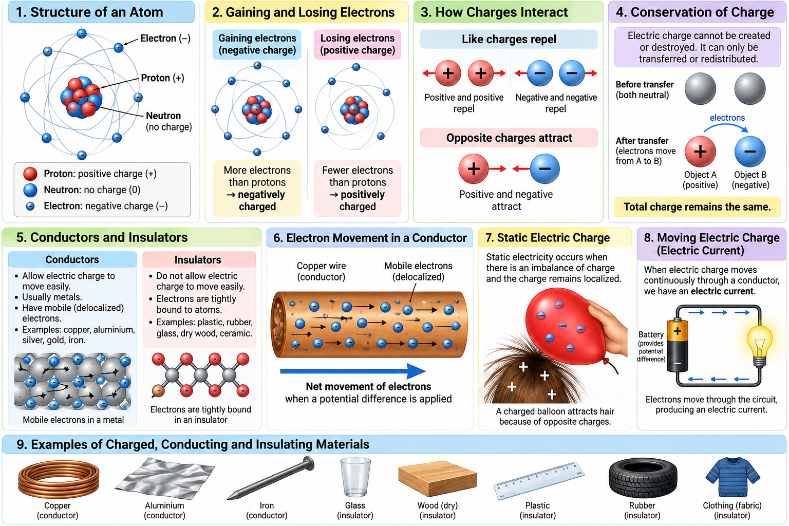
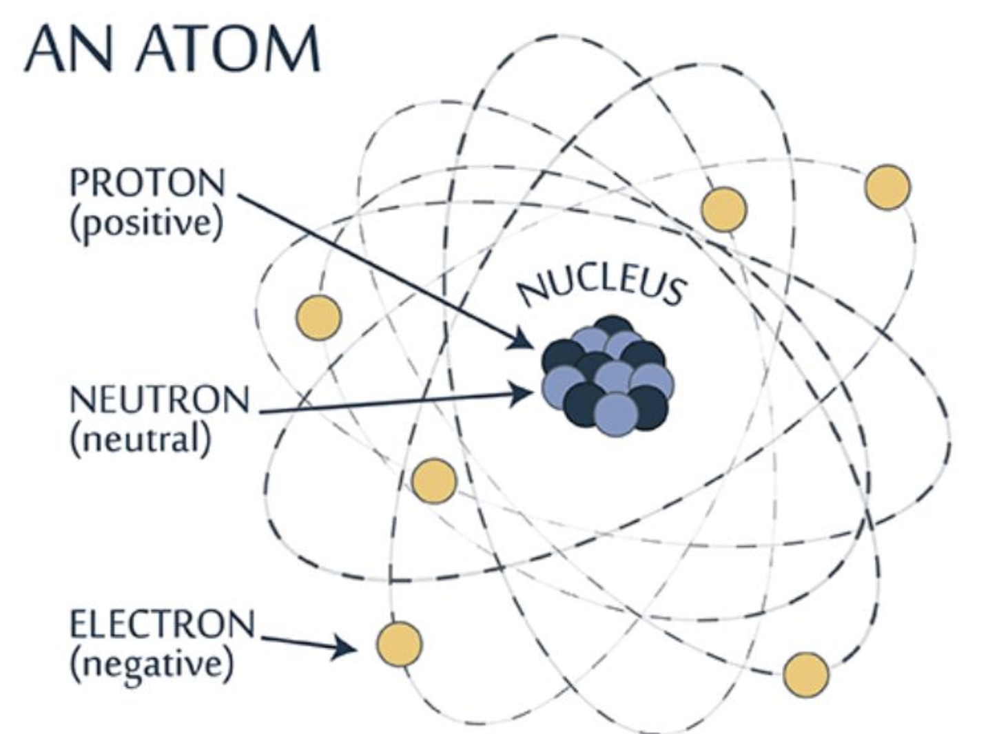
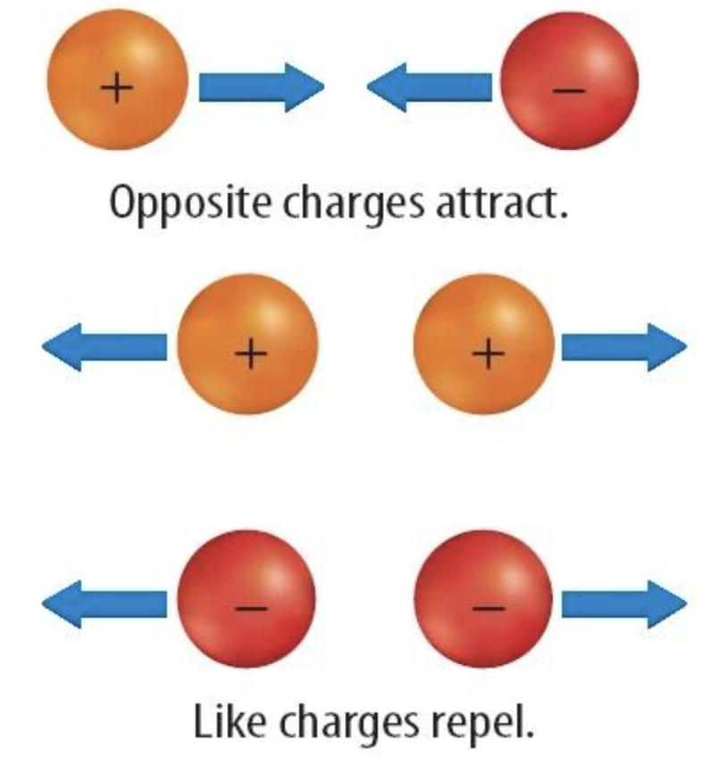
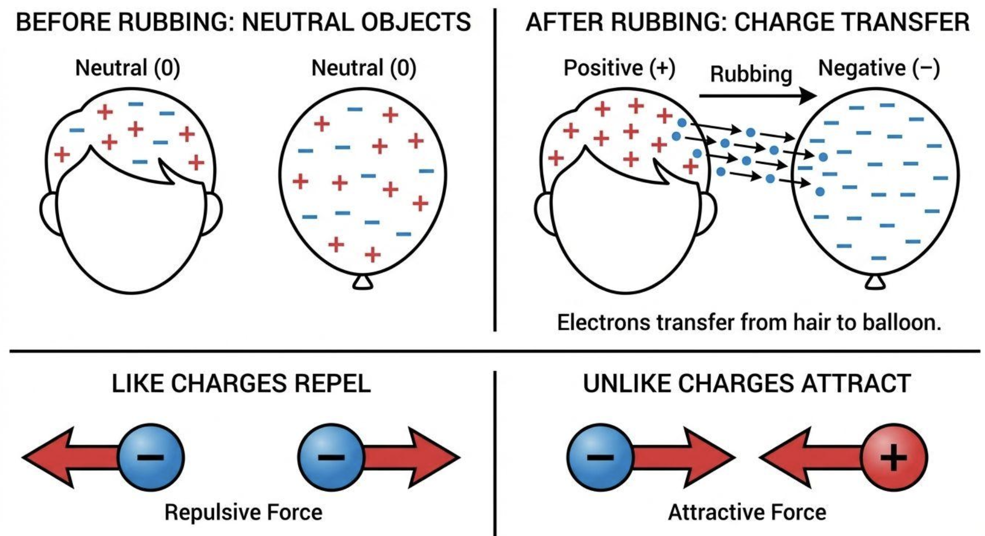
- I can describe positive and negative electric charge.
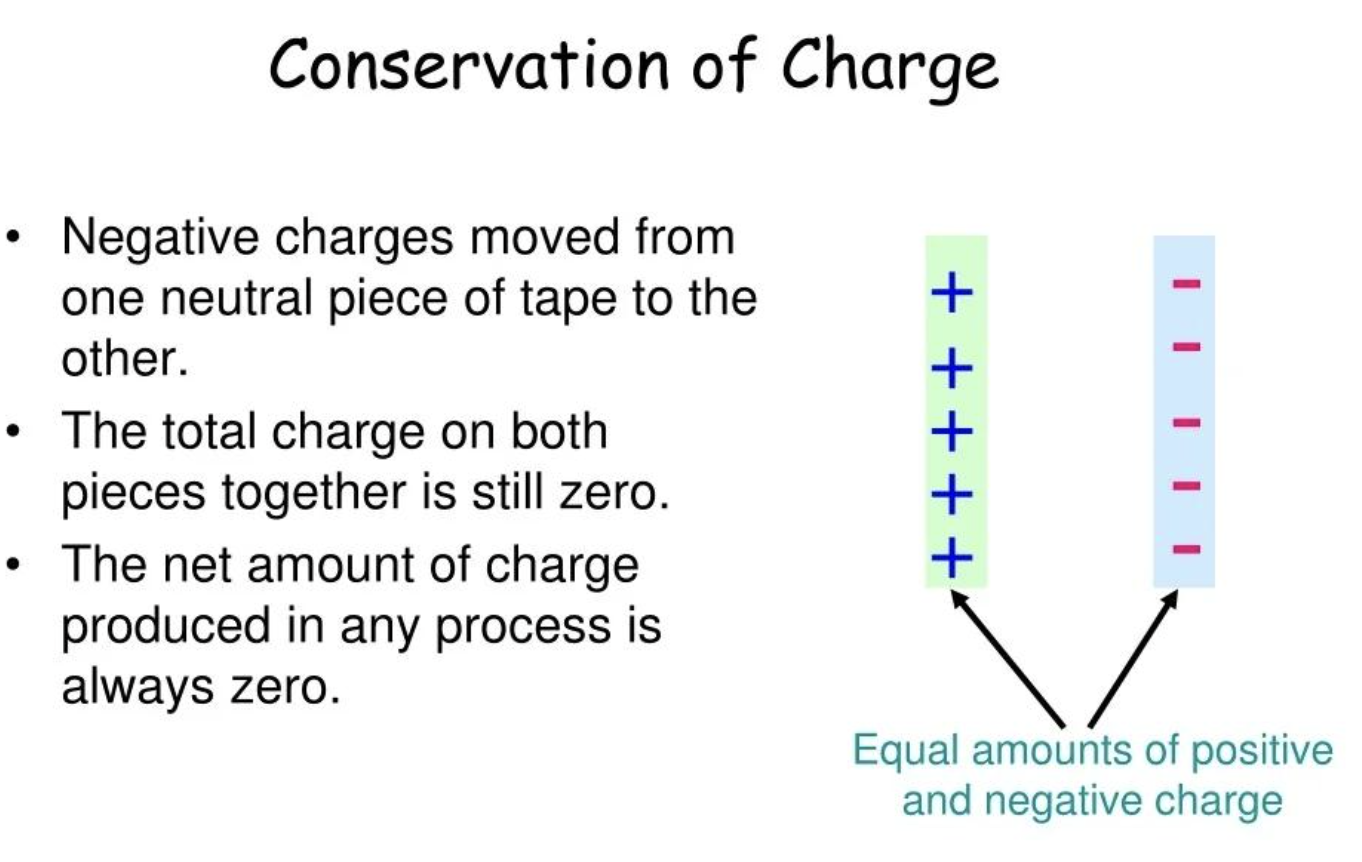
- I can explain how charge is conserved.
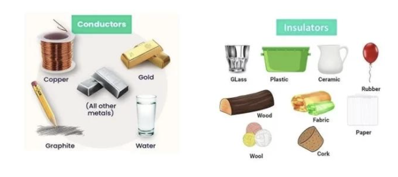
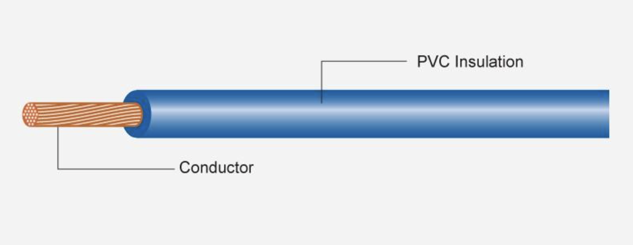
- I can distinguish between conductors and insulators.
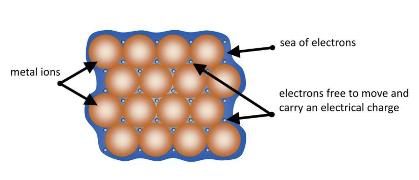
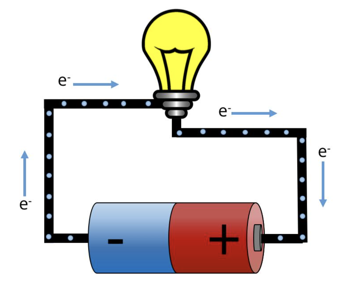
- I can describe how electrons move in conductive materials.
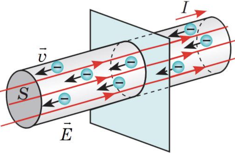
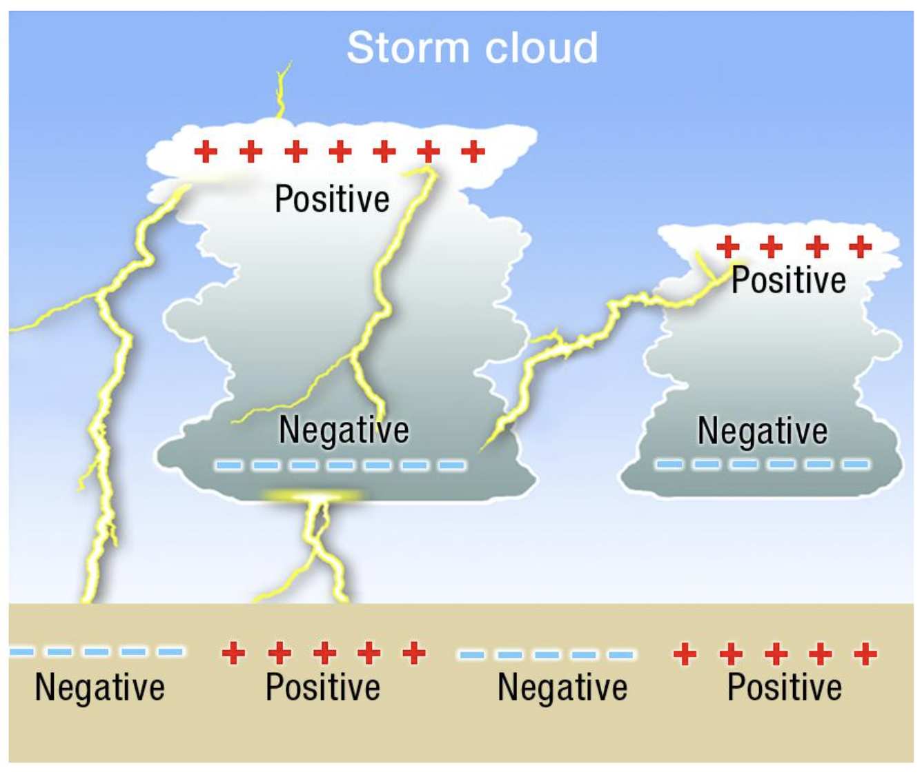
- I can explain static and moving electric charge.

2. Electric Current
Learning outcomes
- I can define electric current.
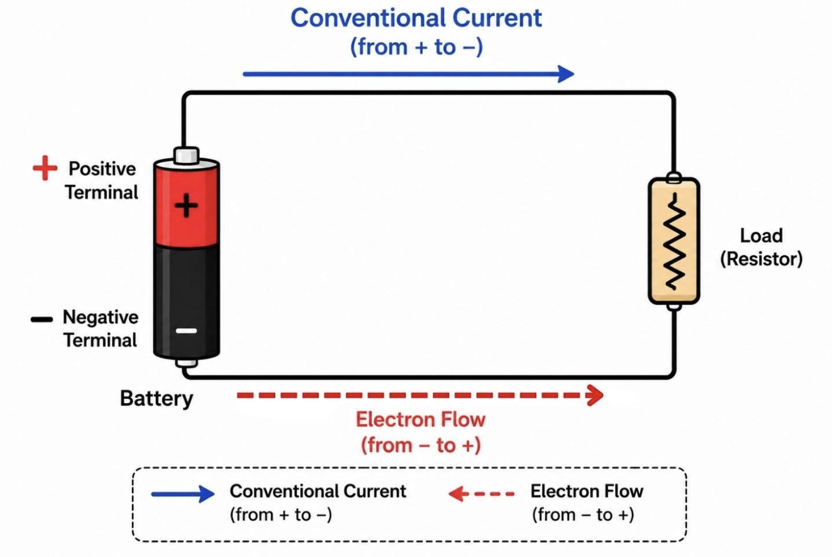
- I can distinguish between conventional current and electron flow.
- I can identify the SI unit of current.
- I can explain how current is measured.
- I can relate current to the movement of charge.
What Is Electric Current?
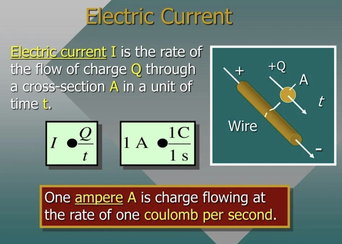
Electric current is the rate at which electric charge flows past a point in a circuit.
In a metal wire, the moving charged particles are electrons. When a complete circuit is connected to a source such as a cell or battery, electrons have a net movement through the conducting wires.
We describe this movement of charge using current.
A useful way to think about it is:
more charge passing each second → larger current
less charge passing each second → smaller current
Current does not tell us how much charge exists in the entire circuit. Instead, it tells us how quickly charge passes a particular point.
Current as a Rate of Flow
Imagine standing beside a road and counting cars.
If 5 cars pass you each minute, the traffic flow is relatively small.
If 100 cars pass you each minute, the traffic flow is much larger.
Electric current is similar, except instead of counting cars, we consider electric charge.
The relationship is:
\[ \boxed{I=\frac{Q}{t}} \]
where:
- \(I\) = electric current
- \(Q\) = electric charge
- \(t\) = time
Current therefore tells us how much charge passes a point per unit time.
The Unit of Electric Current
The SI unit of electric current is the ampere.
Its symbol is:
\[ \boxed{A} \]
The ampere is named after French physicist and mathematician André-Marie Ampère, whose work contributed greatly to our understanding of electricity and magnetism.
In equations, electric current is usually represented by the symbol:
\[ \boxed{I} \]
So we might write:
\[ I=2\text{ A} \]
This means that the electric current is 2 amperes.
What Does One Ampere Mean?
Charge is measured in coulombs (C).
One ampere means that one coulomb of charge passes a point every second.
Therefore:
\[ \boxed{1\text{ A}=1\text{ C/s}} \]
This is an extremely important relationship.
For example:
If 5 C of charge passes a point every second:
\[ I=5\text{ A} \]
If only 0.5 C passes every second:
\[ I=0.5\text{ A} \]
Current is therefore fundamentally a measurement of the rate of movement of electric charge.
Calculating Current
The equation for current is:
\[ I=\frac{Q}{t} \]
Worked Example 1
Suppose 20 C of charge passes through a wire in 5 seconds.
\[ I=\frac{Q}{t} \]
Substitute the values:
\[ I=\frac{20}{5} \]\[ \boxed{I=4\text{ A}} \]
The current is 4 A.
This means charge is passing the point at an average rate of 4 coulombs per second.
Rearranging the Current Equation
The equation:
\[ I=\frac{Q}{t} \]
can also be rearranged.
To calculate charge:
\[ \boxed{Q=It} \]
To calculate time:
\[ \boxed{t=\frac{Q}{I}} \]
So we have three useful forms:
\[ \boxed{I=\frac{Q}{t}} \]\[ \boxed{Q=It} \]\[ \boxed{t=\frac{Q}{I}} \]
Worked Example 2: Finding Charge
A current of 3 A flows for 10 seconds.
How much charge passes through the circuit?
Use:
\[ Q=It \]\[ Q=3\times10 \]\[ \boxed{Q=30\text{ C}} \]
Therefore, 30 coulombs of charge pass through the circuit.
Worked Example 3: Finding Time
A total charge of 24 C passes through a component while the current is 6 A.
How long does this take?
Use:
\[ t=\frac{Q}{I} \]\[ t=\frac{24}{6} \]\[ \boxed{t=4\text{ s}} \]
What Is Actually Moving?
In a metallic conductor, such as a copper wire, the moving charge carriers are electrons.
Metals contain large numbers of mobile or delocalized electrons.
When no electric field is present, these electrons already move randomly through the material.
However, random movement does not produce a net current.
When a source such as a battery establishes an electric field through a complete circuit, the electrons acquire an overall drift direction.
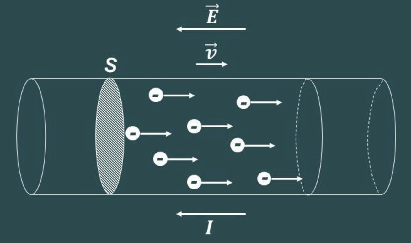
It is this net movement of charge that produces electric current.
Electron Flow
Electrons have a negative charge.
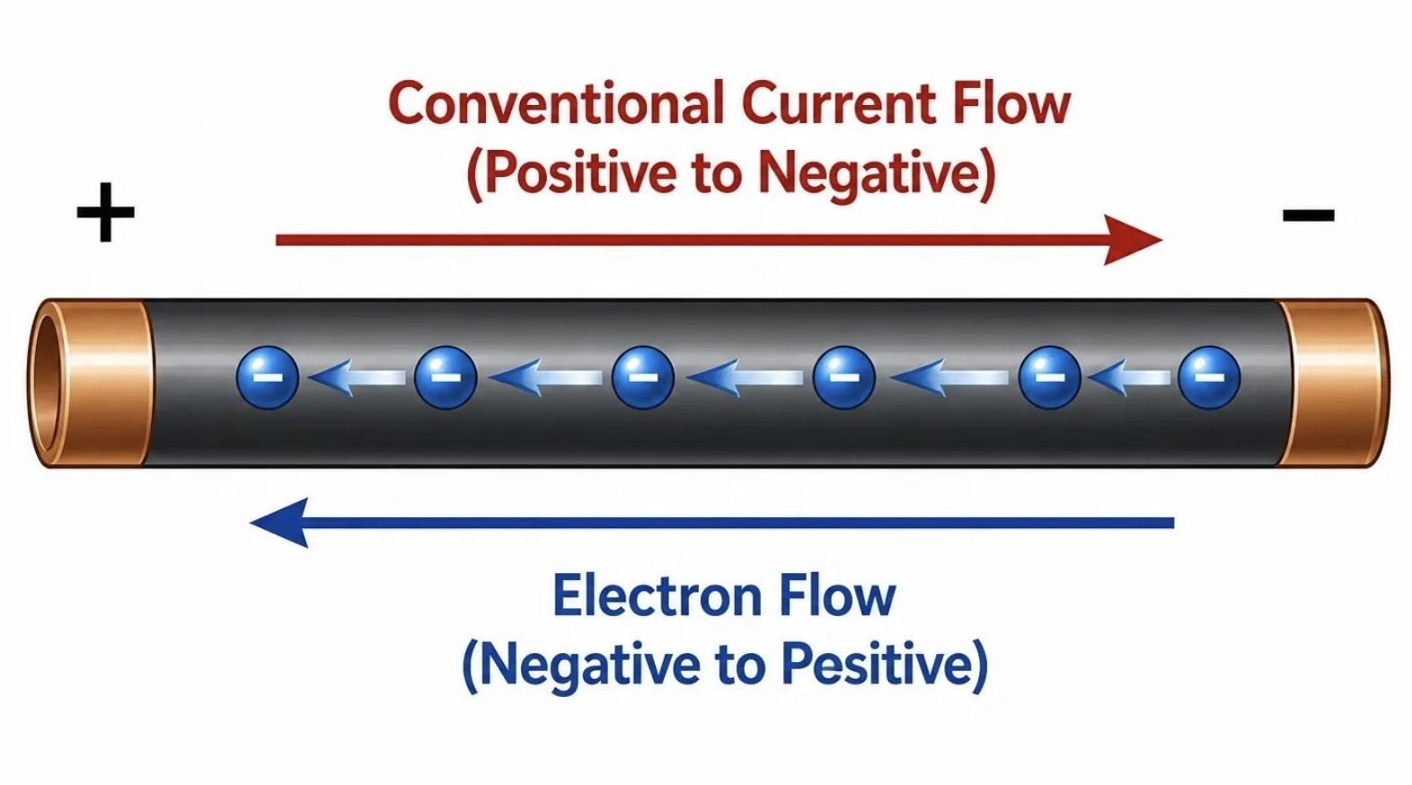
In the external metallic part of a simple DC circuit, their net drift is:
\[ \boxed{\text{negative terminal}\rightarrow\text{positive terminal}} \]
This direction is called electron flow.
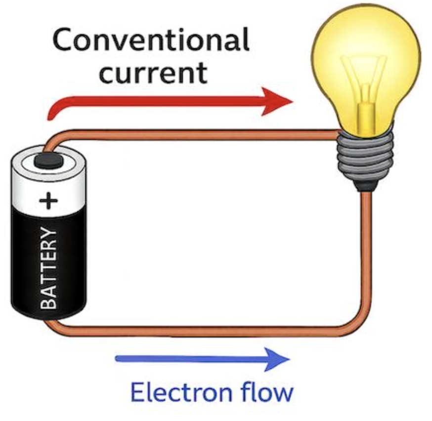
However, this creates an important complication.
Circuit diagrams usually show current travelling in the opposite direction.
Conventional Current
Before scientists discovered electrons, they had already chosen a direction to represent electric current.
They assumed that positive charge moved from the positive terminal toward the negative terminal.
This direction became known as conventional current.
Therefore:
Conventional current
\[ \boxed{+\rightarrow-} \]
Electron flow in metallic conductors
\[ \boxed{-\rightarrow+} \]
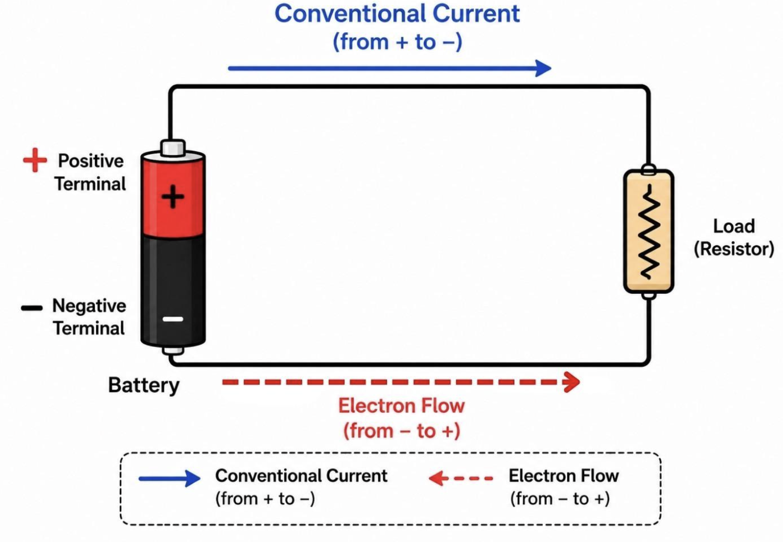
Both directions are useful descriptions, but they refer to different conventions.
In most circuit diagrams and calculations, we use conventional current.
Why Do We Still Use Conventional Current?
It might seem strange to keep using conventional current when we know electrons move in the opposite direction through metal wires.
The reason is largely historical.
Scientists developed many of the rules and symbols of circuit theory before the electron was discovered. By the time scientists understood electron motion, conventional current was already deeply established.
Changing every equation, diagram, textbook, and engineering convention would have created unnecessary confusion.
So conventional current remains the standard.
Remember:
Circuit arrows usually show conventional current.
They do not usually show the direction that electrons drift through a metal wire.
Comparing Electron Flow and Conventional Current
| Electron Flow | Conventional Current |
|---|---|
| Describes movement of electrons in metals | Standard direction used for current |
| Electrons are negatively charged | Treats current direction as movement of positive charge |
| Negative → positive | Positive → negative |
| Describes the actual charge-carrier drift in metallic wires | Used in most circuit diagrams and calculations |
A common mistake is to assume that one direction must be "wrong."
It isn't.
They are simply different ways of describing charge transport.
Measuring Electric Current
Electric current is measured using an instrument called an ammeter.
The circuit symbol for an ammeter is usually shown as:
\[ \boxed{\text{Ⓐ}} \]
An ammeter measures the amount of current flowing through a particular part of a circuit.
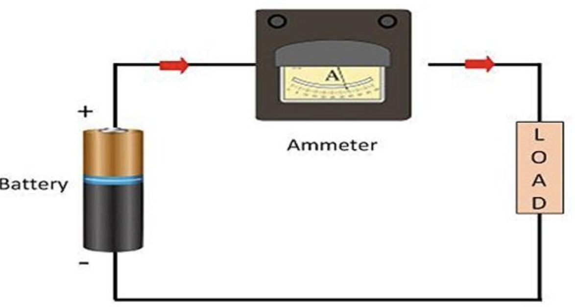
To measure current correctly, the ammeter must be placed so that the current being measured passes through the ammeter.
This means the ammeter is connected in series with the component.
Connecting an Ammeter
Suppose we want to measure the current through a lamp.
The circuit might contain:
cell → ammeter → lamp → cell
The ammeter becomes part of the conducting path.
The current flows through:
- the wire
- the ammeter
- the lamp
- the remaining wire
- back to the source
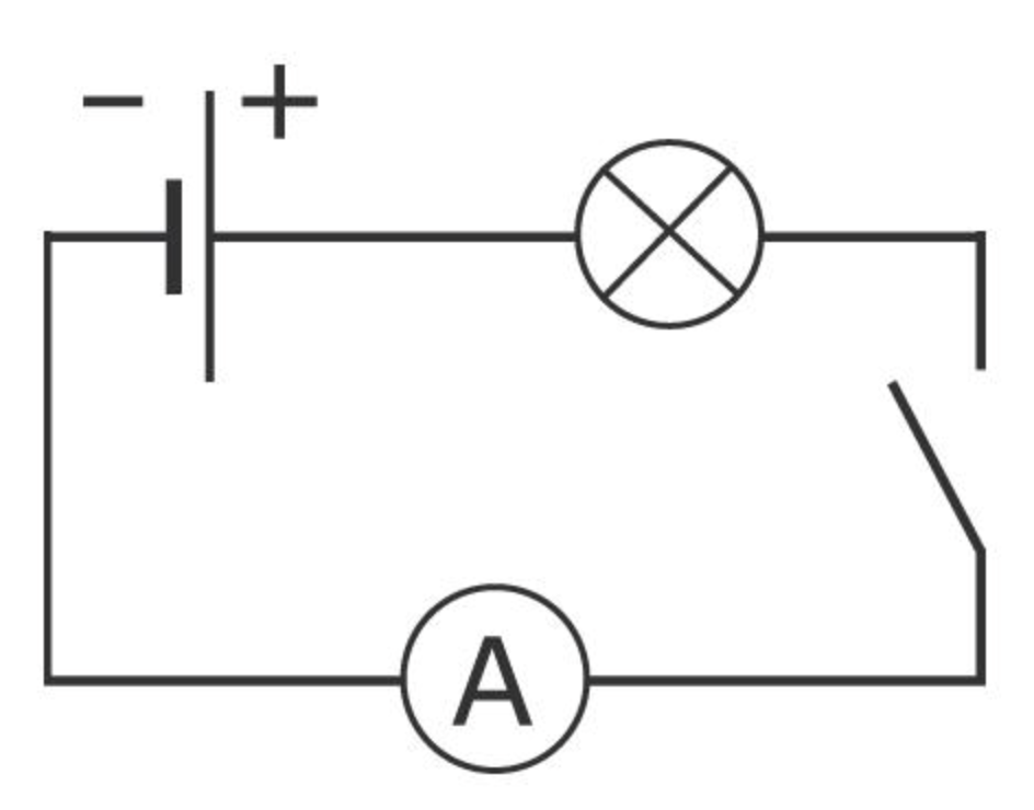
Because the charge passes through the ammeter, the instrument can measure the rate at which charge is flowing.
Ammeters Are Connected in Series
This is one of the most important practical rules when measuring current:
\[ \boxed{\text{An ammeter is connected in series.}} \]
Why?
Because the charge flowing through the component must also flow through the ammeter.
If we want to know the current through a lamp, the ammeter must therefore be placed in the same current path as the lamp.
Later, when we study voltage, we will see that voltmeters are connected differently.
Using a Digital Multimeter
In laboratories, current is often measured using a digital multimeter rather than a dedicated ammeter.
A multimeter can usually measure several electrical quantities, including:
- current
- voltage
- resistance
To measure current, the meter must be placed in the correct current-measuring mode and connected in series with the circuit.
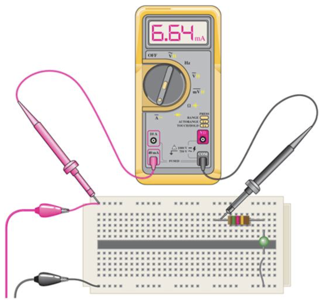
The correct terminals and range must also be selected.
Incorrectly connecting a multimeter while it is set to measure current can create a very low-resistance path, so laboratory instructions and meter ratings should always be followed.
Current in a Simple Series Circuit
Consider a simple circuit containing:
- one cell
- one switch
- one lamp
When the switch is open, the conducting path is incomplete.
There is no sustained current around the circuit.
When the switch is closed, a complete conducting path exists.
Current can then flow.
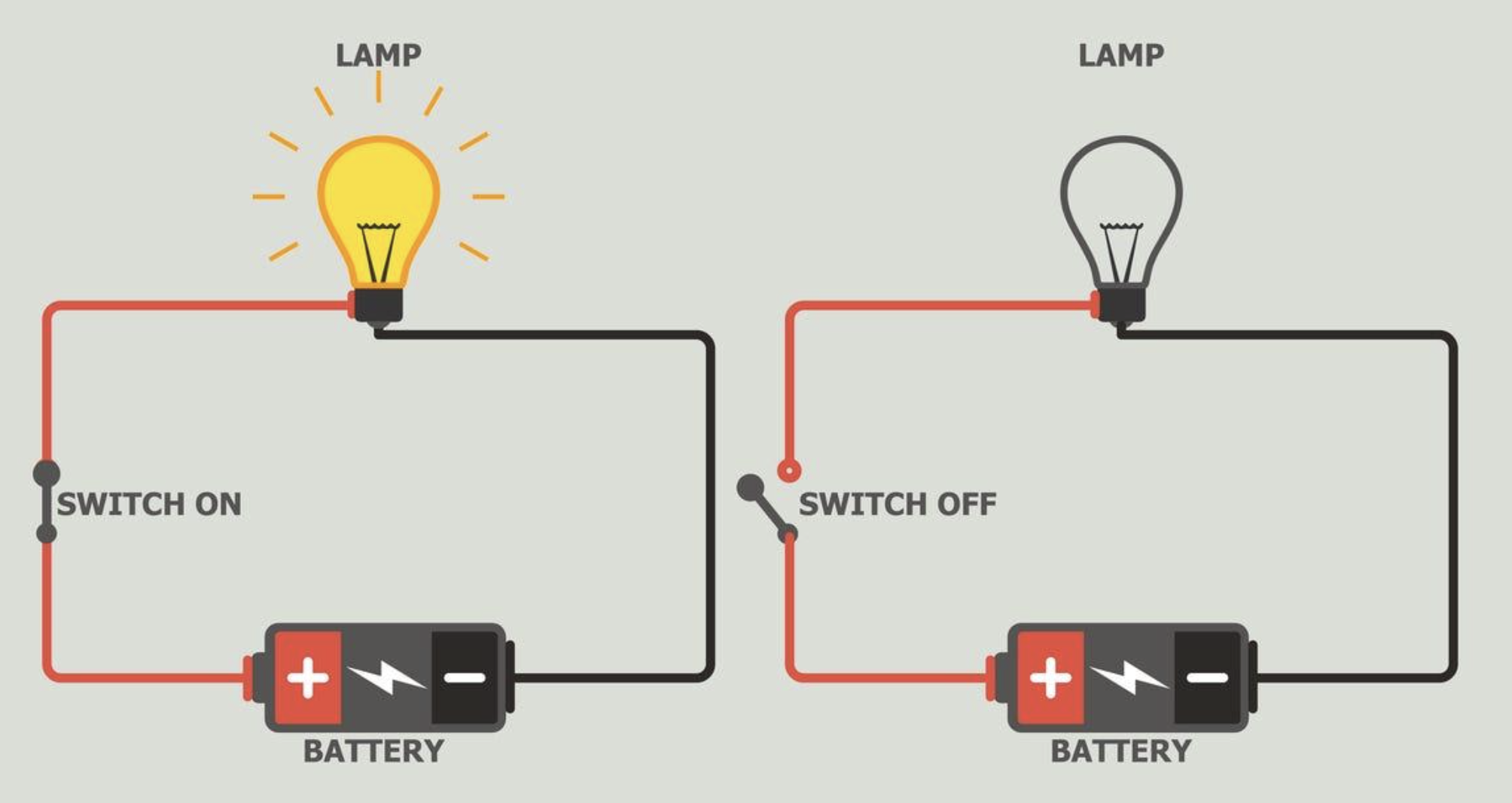
This gives us an important principle:
A sustained current requires a complete conducting path.
Current Is Not "Used Up"
A very common misconception is that a lamp "uses up" current.
It does not.
In a simple series circuit operating steadily, charge does not disappear as it passes through a lamp.
Charge is conserved.
Therefore, the rate of charge flow through one point in a simple series circuit is the same as the rate of charge flow through another point.
Imagine measuring current immediately before and immediately after a lamp.
If:
\[ I_{\text{before}}=0.50\text{ A} \]
then, for a simple steady series circuit:
\[ I_{\text{after}}=0.50\text{ A} \]
The lamp transfers energy, but it does not consume electric charge.
Current and Charge Conservation
Suppose a current of 2 A enters a lamp.
This means:
\[ 2\text{ C} \]
of charge passes into the lamp every second.
If only 1 C per second came out, charge would continuously accumulate inside the lamp.
That does not happen during normal steady operation.
Instead:
\[ 2\text{ C/s enters} \]
and
\[ 2\text{ C/s leaves} \]
Therefore:
\[ I_{\text{in}}=I_{\text{out}} \]
This is another consequence of conservation of charge.
Does a Larger Current Mean Faster Electrons?
This needs careful interpretation.
A larger current means more charge passes a point each second.
That can be related to factors including:
- the number of available charge carriers
- the charge carried by each particle
- their average drift speed
- the cross-sectional area of the conductor
So current is not simply "how fast an electron moves."
Current measures the rate of charge flow.
Large and Small Currents
Not every electrical device operates with the same current.
Very small currents may be measured in:
Milliamperes
\[ 1\text{ mA}=0.001\text{ A} \]
or:
\[ 1000\text{ mA}=1\text{ A} \]
Even smaller currents can be measured in microamperes (μA).
For example:
\[ 1\text{ μA}=0.000001\text{ A} \]
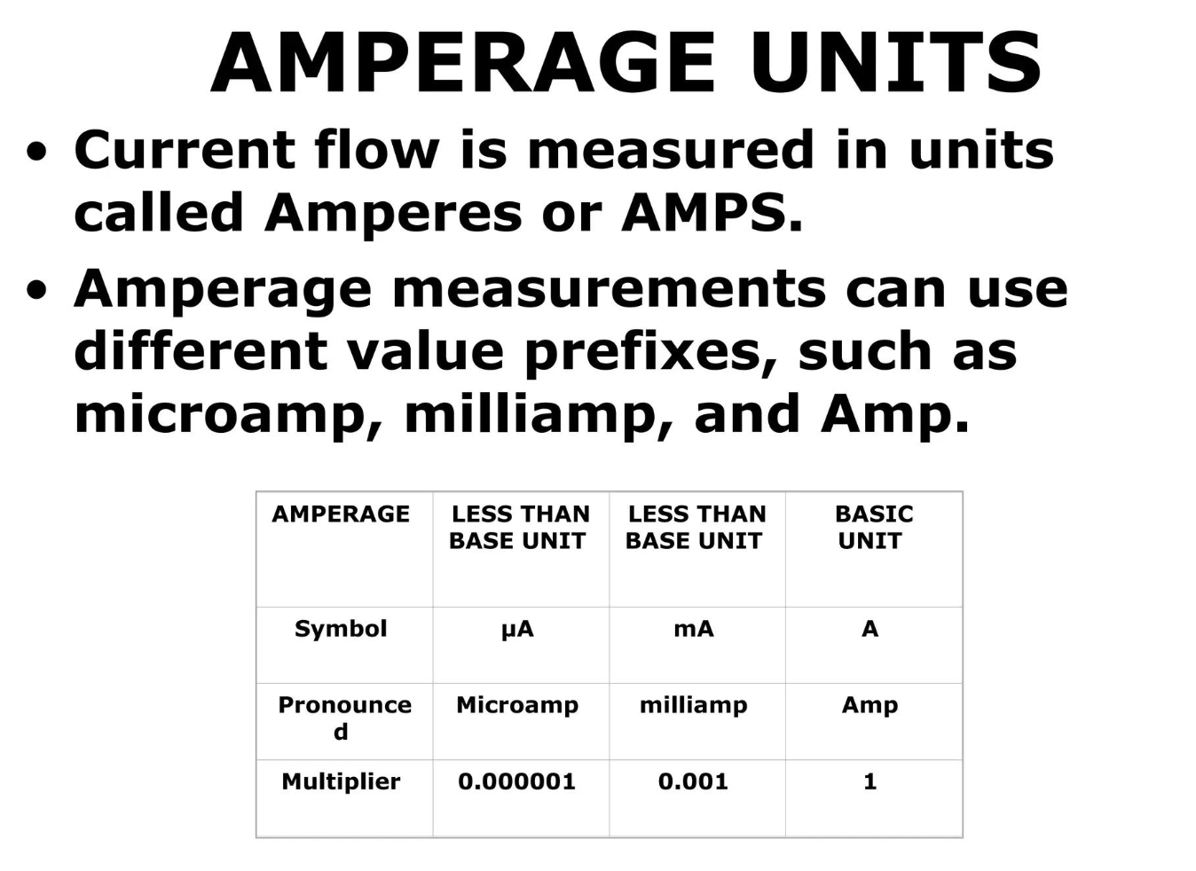
Being comfortable converting between amperes and milliamperes is useful when reading meters and working with electronic circuits.
Worked Example: Milliamperes
A meter reads:
\[ 250\text{ mA} \]
Convert this to amperes.
Because:
\[ 1000\text{ mA}=1\text{ A} \]
divide by 1000:
\[ 250\div1000=0.250 \]
Therefore:
\[ \boxed{250\text{ mA}=0.250\text{ A}} \]
Worked Example: Comparing Currents
Two circuits are measured.
Circuit A
\[ I=0.8\text{ A} \]
Circuit B
\[ I=1.5\text{ A} \]
Circuit B has the larger current.
This means that charge is passing a point at a greater rate in Circuit B.
It does not mean Circuit B contains "more electricity." Current specifically describes the rate of charge flow.
A Useful Analogy: Water Flow
Electric current is sometimes compared with water flowing through a pipe.
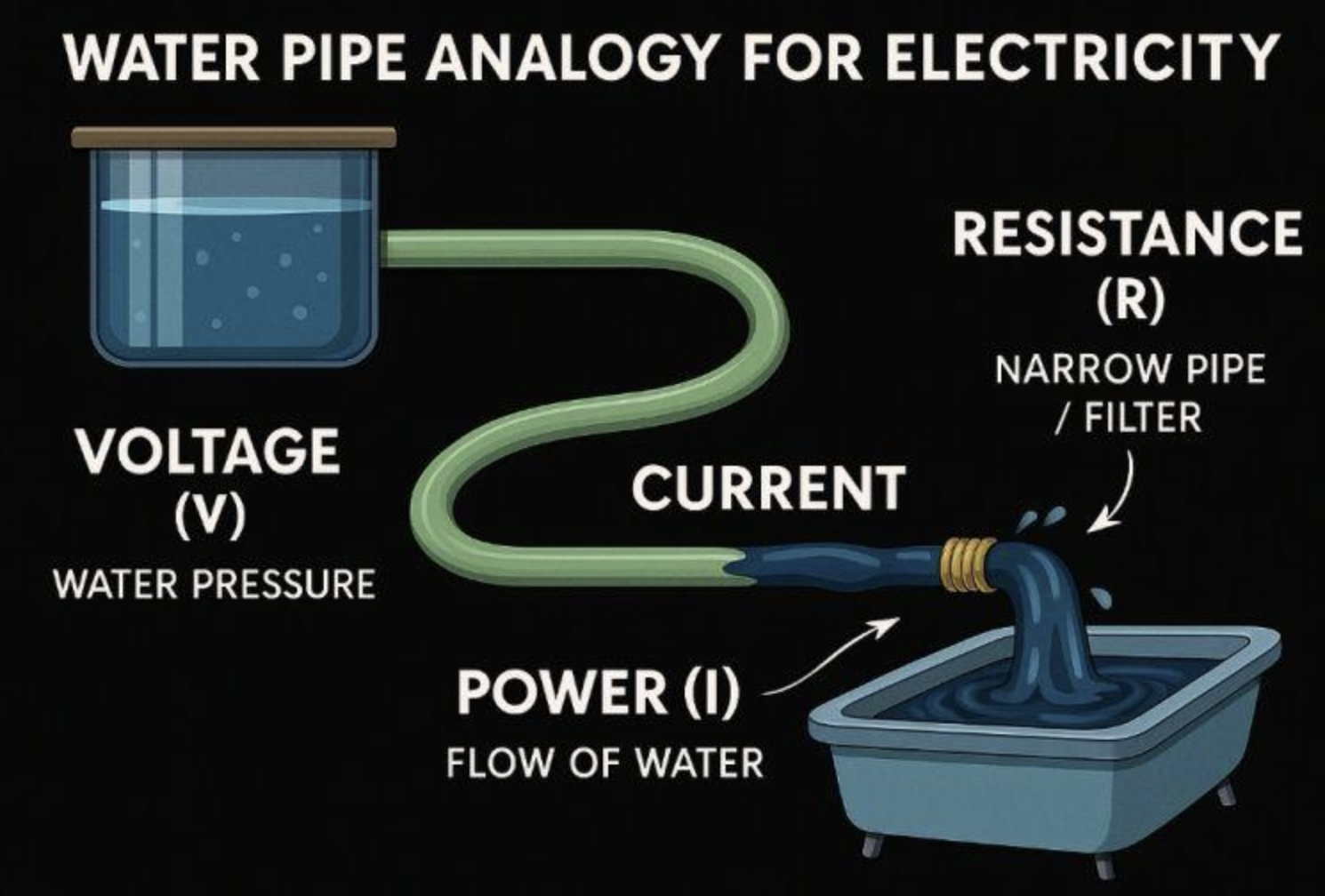
Imagine measuring how much water passes through a pipe every second.
A small flow:
small amount of water per second
A large flow:
large amount of water per second
Similarly:
small current → small amount of charge per second
large current → large amount of charge per second
The analogy is useful for understanding rate of flow, although electric circuits do not behave exactly like water systems.
Real-World Connections
Electric current is important in almost every electrical technology.
Phone Chargers
Chargers are labelled with current ratings, often expressed in amperes.
Household Appliances
Different appliances require different currents depending on their electrical characteristics and operating conditions.
Electronics
Small electronic components may operate with currents measured in milliamperes or even microamperes.
Electric Motors
Electric motors rely on electric current flowing through conductors to produce magnetic effects.
Circuit Protection
Fuses and circuit breakers are designed to respond when current becomes too large for a circuit.
Understanding current is therefore important both for designing circuits and for using electrical systems safely.
Common Mistakes
Mistake 1: Current is the amount of charge
Current is not simply charge.
Current is the rate at which charge flows:
\[ I=\frac{Q}{t} \]
Mistake 2: Current is measured in coulombs
Charge is measured in coulombs (C).
Current is measured in amperes (A).
Mistake 3: Electrons move in the direction of conventional current
In metallic conductors, they move in opposite directions.
Electron flow: − → +
Conventional current: + → −
Mistake 4: An ammeter is connected across a component
An ammeter is normally connected in series so that the current being measured passes through it.
Mistake 5: Components use up current
Components can transfer electrical energy into other forms, but electric charge is conserved.
Current is not gradually "used up" as it travels around a simple series circuit.
Mistake 6: A larger current simply means individual electrons are moving extremely quickly around the circuit
Current measures charge passing per second. Electron drift speed is a related but different concept.
Check Your Understanding
1. Define electric current.
2. What is the SI unit of electric current?
3. What symbol is used for the ampere?
4. What quantity is measured in coulombs?
5. Explain what a current of 1 A means.
6. Calculate the current if 12 C of charge passes a point in 3 seconds.
7. A current of 4 A flows for 5 seconds. Calculate the charge transferred.
8. 30 C of charge passes a point while the current is 5 A. Calculate the time.
9. State the direction of conventional current through the external circuit of a simple cell.
10. State the direction of electron flow through the metallic wires.
11. Explain why conventional current and electron flow point in opposite directions.
12. What instrument is used to measure electric current?
13. How should an ammeter be connected in a circuit?
14. Convert 500 mA into amperes.
15. Convert 0.075 A into milliamperes.
16. Explain why saying that a lamp "uses up current" is incorrect.
17. Circuit A carries 0.4 A and Circuit B carries 1.2 A. What does this tell you about the rates of charge flow?
18. Challenge: A current of 2.5 A flows through a wire for 3 minutes. Calculate the total charge that passes through the wire.
Key Terms
- Electric current – the rate of flow of electric charge.
- Charge – an electrical property of matter measured in coulombs.
- Coulomb (C) – the SI unit of electric charge.
- Ampere (A) – the SI unit of electric current.
- Ammeter – an instrument used to measure electric current.
- Electron flow – the net movement of electrons through a conductor.
- Conventional current – the standard current direction from positive toward negative in an external circuit.
- Drift – the overall directional movement of charge carriers in response to an electric field.
- Series connection – a connection in which components lie along the same current path.
- Milliampere (mA) – one thousandth of an ampere.
- Complete circuit – a continuous conducting path through which sustained current can flow.
Key Takeaways
- Electric current is the rate of flow of electric charge.
- Current is represented by the symbol \(I\).
- The SI unit of current is the ampere (A).
- One ampere means one coulomb of charge passes a point each second:
\[ \boxed{1\text{ A}=1\text{ C/s}} \]
- Current can be calculated using:
\[ \boxed{I=\frac{Q}{t}} \]
- Charge can be calculated using:
\[ \boxed{Q=It} \]
- In metallic conductors, mobile electrons carry charge.
- Electron flow through the external circuit is from negative to positive.
- Conventional current is defined in the opposite direction, from positive to negative.
- Current is measured using an ammeter.
- An ammeter is connected in series with the part of the circuit being measured.
- Current is not "used up" by a circuit component; electric charge is conserved.
- A larger current means more charge passes a point each second.
3. Voltage and Potential Difference
Learning outcomes
- I can define voltage as electrical potential difference.
- I can explain how batteries produce voltage.
- I can distinguish between voltage and current.
- I can predict how voltage affects current.
- I can measure voltage using a voltmeter.
What Is Voltage?
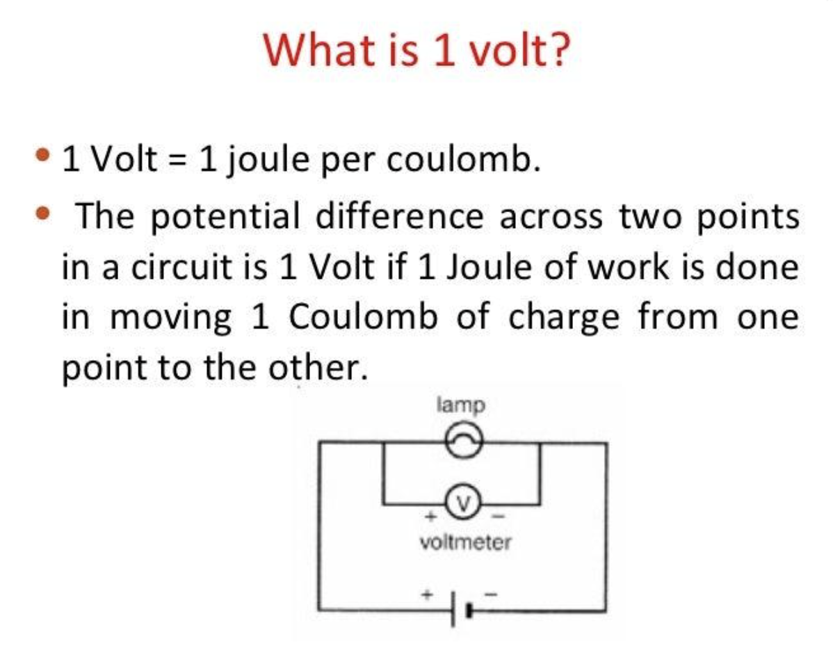
Voltage is another name for electrical potential difference.
It describes the difference in electrical potential energy between two points in a circuit.
A useful definition is:
Voltage is the energy transferred per unit charge.
The equation is:
\[ \boxed{V=\frac{E}{Q}} \]
where:
- \(V\) = voltage or potential difference
- \(E\) = energy transferred
- \(Q\) = electric charge
The SI unit of voltage is the volt (V).
One volt means that 1 joule of energy is transferred for every 1 coulomb of charge:
\[ \boxed{1\text{ V}=1\text{ J/C}} \]
Understanding Potential Difference
The term potential difference is important because voltage is always measured between two points.
Imagine two locations in a circuit.
If a charge has more electrical potential energy at one point than another, there is a potential difference between those points.
When charge moves between them, energy can be transferred.
This is why voltage is closely connected to what circuit components do.
For example:
- a battery increases the electrical potential energy of charge
- a lamp transfers electrical energy into light and thermal energy
- a motor transfers electrical energy into kinetic energy
Voltage therefore tells us something about the energy transferred by each coulomb of charge.
A Simple Analogy: Height
A useful comparison is gravitational potential energy.
Imagine water stored at the top of a hill.
The water has gravitational potential energy because of its height.
As the water moves downhill, its potential energy can be transferred into other forms.
Similarly, a battery creates a difference in electrical potential between its terminals.
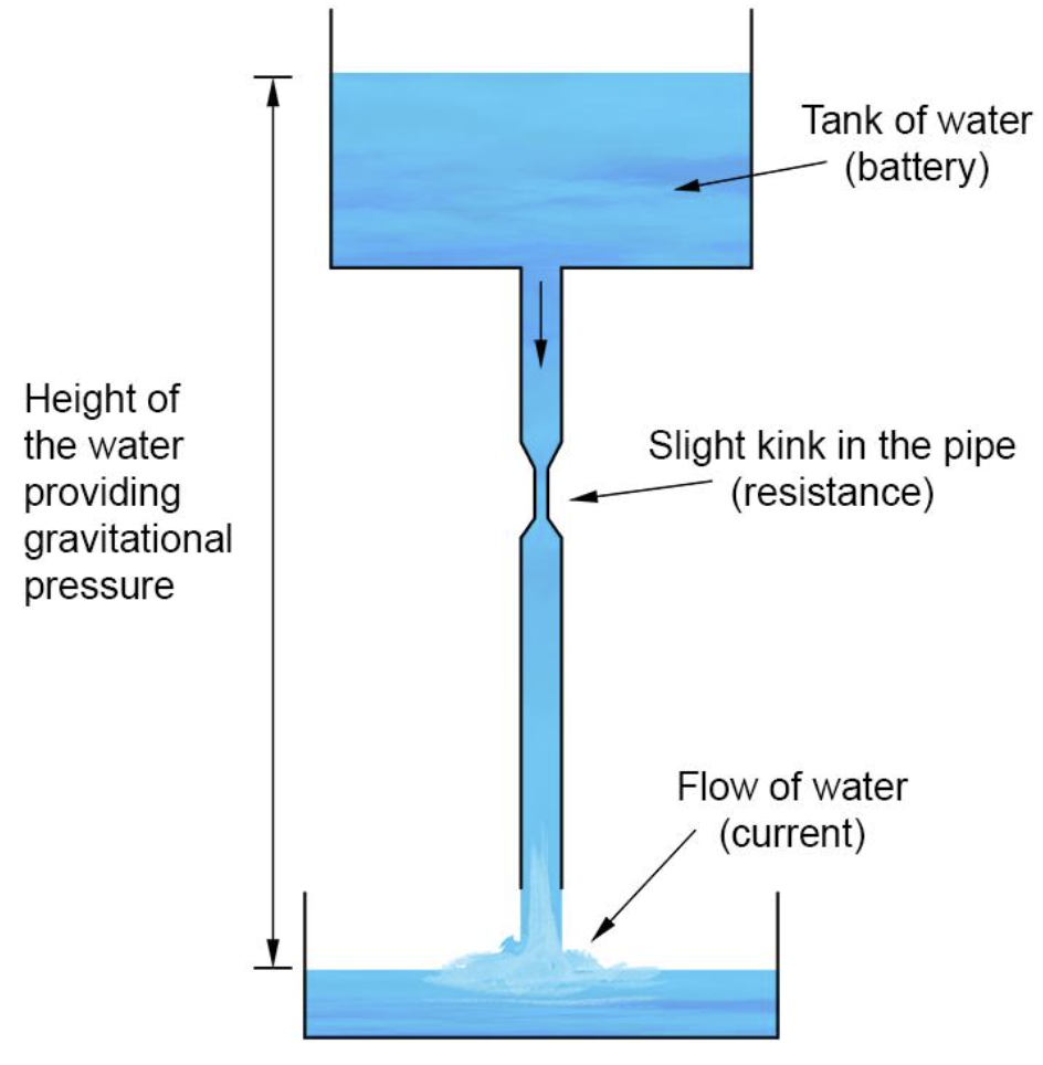
This analogy is useful because:
greater height difference → greater gravitational potential difference
and similarly:
greater voltage → greater electrical potential difference
However, voltage is not literally height or water pressure. It is an electrical quantity measured in volts.
How Batteries Produce Voltage
A battery produces voltage using chemical reactions.
Inside a battery, chemical processes separate electric charge and maintain a difference in electric potential between the terminals.
One terminal becomes relatively:
negative
while the other becomes relatively:
positive
This separation creates an electric potential difference.
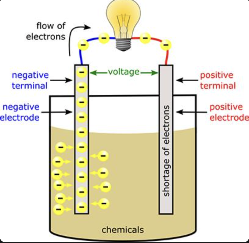
When the battery is connected into a complete circuit, the electric field established around the circuit causes charge carriers in the conductors to have a net movement.
The battery continuously converts:
chemical energy → electrical energy
as long as the relevant chemical reactions can continue.
Cells and Batteries
A single electrochemical source is often called a cell.
A battery technically consists of two or more cells connected together, although in everyday language we commonly call individual cells "batteries."
A typical cell might provide:
\[ 1.5\text{ V} \]
This means approximately:
\[ 1.5\text{ J} \]
of energy is transferred per coulomb of charge.
So:
\[ 1.5\text{ V}=1.5\text{ J/C} \]
Worked Example: Energy per Charge
A battery provides 12 J of electrical energy to 3 C of charge.
Calculate the voltage.
Use:
\[ V=\frac{E}{Q} \]
Substitute:
\[ V=\frac{12}{3} \]\[ \boxed{V=4\text{ V}} \]
The battery provides 4 joules of energy per coulomb of charge.
Rearranging the Voltage Equation
Starting with:
\[ V=\frac{E}{Q} \]
we can calculate energy using:
\[ \boxed{E=VQ} \]
and charge using:
\[ \boxed{Q=\frac{E}{V}} \]
So the three useful forms are:
\[ V=\frac{E}{Q} \]\[ E=VQ \]\[ Q=\frac{E}{V} \]
Worked Example: Calculating Energy
A charge of 5 C moves through a potential difference of 6 V.
How much energy is transferred?
Use:
\[ E=VQ \]\[ E=6\times5 \]\[ \boxed{E=30\text{ J}} \]
Therefore, 30 J of energy is transferred.
Voltage and Current Are Not the Same
Voltage and current are closely related, but they describe different things.
Voltage
Voltage describes the energy transferred per unit charge.
Unit:
\[ \text{volt (V)} \]
Current
Current describes the rate at which charge flows.
Unit:
\[ \text{ampere (A)} \]
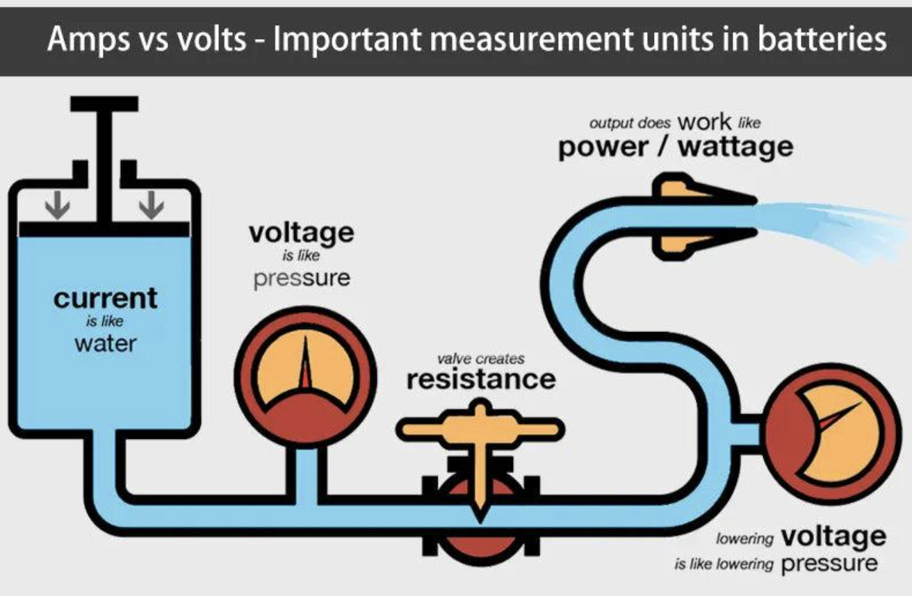
A useful comparison is:
Voltage → energy available per charge
Current → amount of charge flowing per second
These quantities should not be confused.
Voltage Does Not "Flow"
Students sometimes say that "voltage flows through the wire."
That is incorrect.
Charge flows.
The rate of charge flow is current.
Voltage is a difference in electric potential between two points.
So:
Current flows through a component.
Voltage exists across a component.
This distinction becomes very important when connecting meters.
How Voltage Affects Current
In many circuits, increasing voltage causes the current to increase.
Why?
A larger potential difference creates a stronger electric field in the conducting circuit, producing a greater net movement of charge carriers.
For a simple resistor at approximately constant temperature:
higher voltage → higher current
lower voltage → lower current
This relationship is described by Ohm's law.
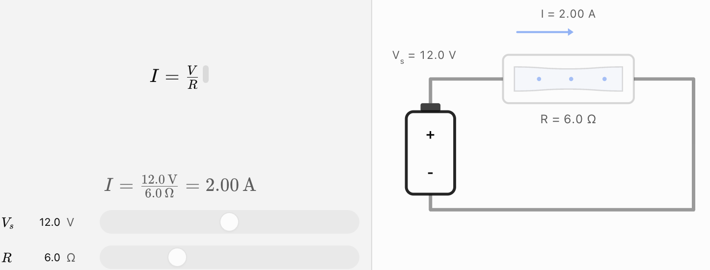
For example, if a resistor has a resistance of \(6\,\Omega\):
At:
\[ V=6\text{ V} \]
the current is:
\[ I=\frac{6}{6}=1\text{ A} \]
At:
\[ V=12\text{ V} \]
the current becomes:
\[ I=\frac{12}{6}=2\text{ A} \]
Doubling the voltage doubled the current because the resistance remained constant.
Voltage, Current, and Resistance
The effect of voltage on current also depends on resistance.
Resistance tells us how strongly a component opposes the flow of electric charge.
For a given resistance:
greater voltage generally produces greater current.
However, two circuits with the same voltage may have different currents if their resistances are different.
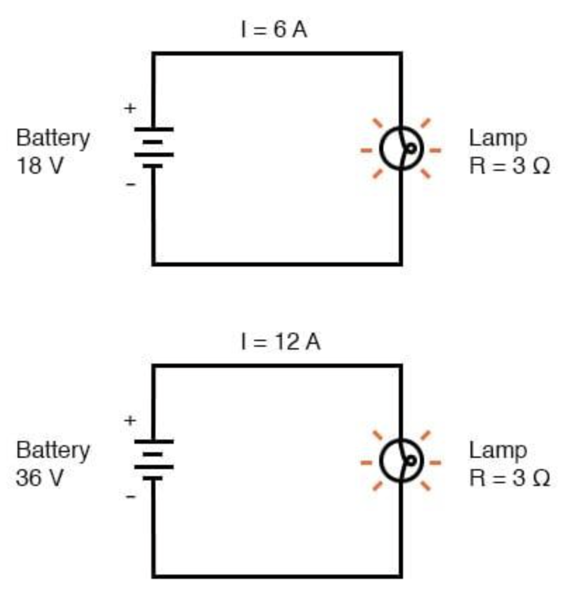
Example
Circuit A:
\[ V=6\text{ V} \]\[ R=3\,\Omega \]\[ I=2\text{ A} \]
Circuit B:
\[ V=6\text{ V} \]\[ R=12\,\Omega \]\[ I=0.5\text{ A} \]
Both circuits have the same voltage, but Circuit A has the larger current because it has less resistance.
Predicting the Effect of Changing Voltage
Suppose a lamp is connected to a variable power supply.
If we gradually increase the voltage, we would generally expect the current through the lamp to increase.
However, real components do not always behave perfectly.
For example, as a filament lamp gets hotter, its resistance increases.
This means that doubling the voltage may not exactly double the current.
Later, this can be studied using current–voltage graphs.
Measuring Voltage
Voltage is measured using an instrument called a voltmeter.
The circuit symbol for a voltmeter is:
\[ \boxed{\text{Ⓥ}} \]
A voltmeter measures the potential difference between two points.
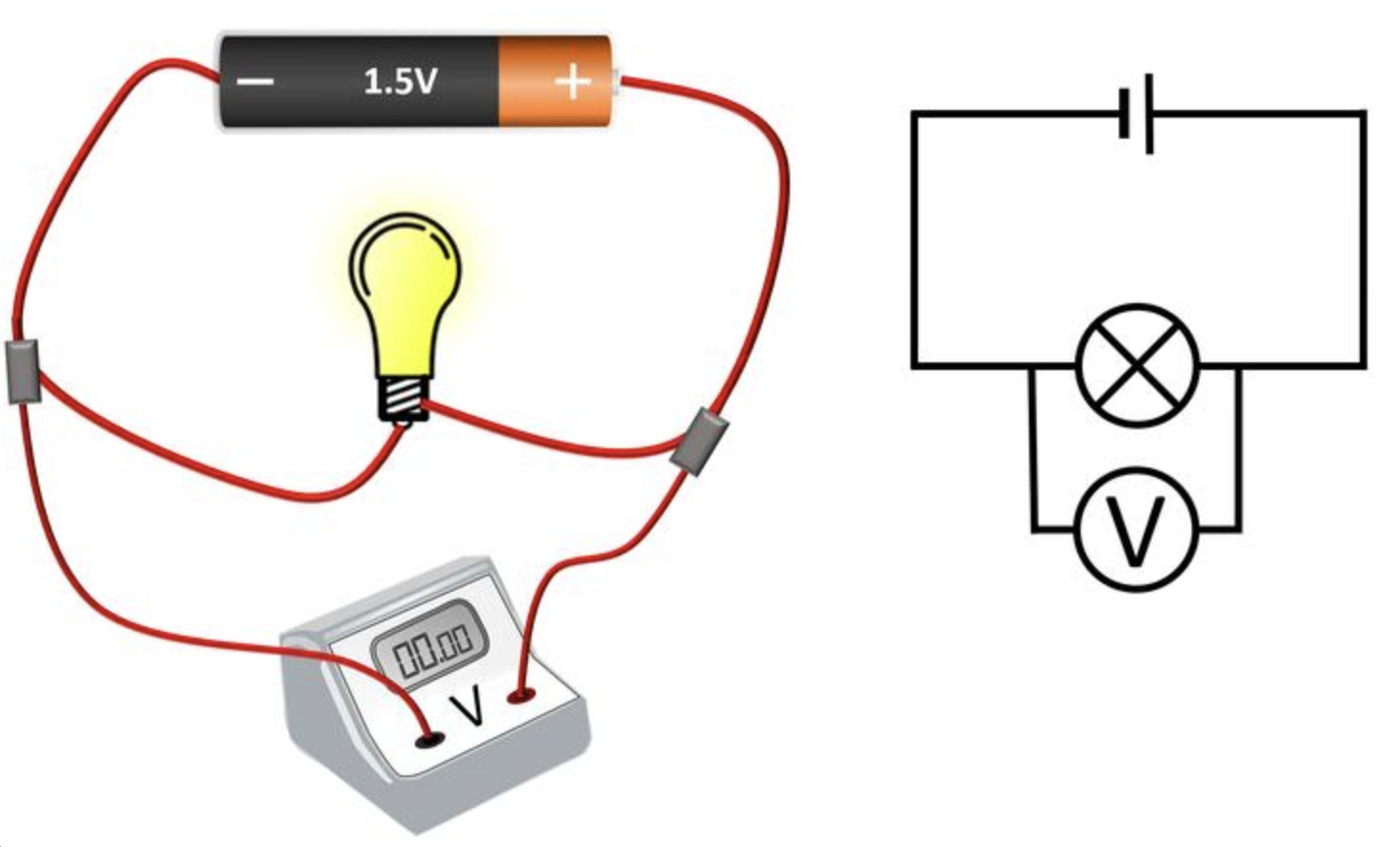
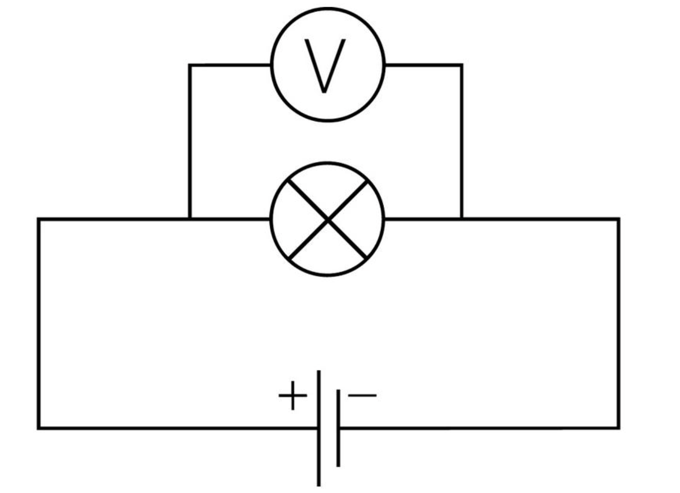
Because voltage is measured between two points, a voltmeter is connected across the component.
This is called a parallel connection.
Connecting a Voltmeter
Suppose we want to measure the voltage across a lamp.
The voltmeter must be connected with one lead on one side of the lamp and the other lead on the other side.
The voltmeter is therefore connected:
\[ \boxed{\text{in parallel with the lamp}} \]
The current does not need to pass through the voltmeter in the same way it passes through an ammeter.
Instead, the voltmeter compares the electrical potential at two points.
Ammeter vs. Voltmeter
It is important to distinguish the two meters.
| Ammeter | Voltmeter |
|---|---|
| Measures current | Measures voltage |
| Unit: ampere (A) | Unit: volt (V) |
| Connected in series | Connected in parallel |
| Current passes through it | Measures between two points |
A good memory rule is:
Ammeter → Along the circuit
Voltmeter → across the component
Why Is a Voltmeter Connected in Parallel?
Voltage is a comparison between two points.
Imagine a lamp.
To find the energy transferred per unit charge by the lamp, we need to compare:
electrical potential before the lamp
with:
electrical potential after the lamp
Therefore, the voltmeter must connect to both sides of the component.
This creates a parallel connection.
Using a Digital Multimeter
A digital multimeter can usually measure:
- voltage
- current
- resistance
When measuring voltage:
- select the appropriate voltage setting
- connect the leads to the correct meter terminals
- place the probes across the two points being compared
- read the voltage from the display
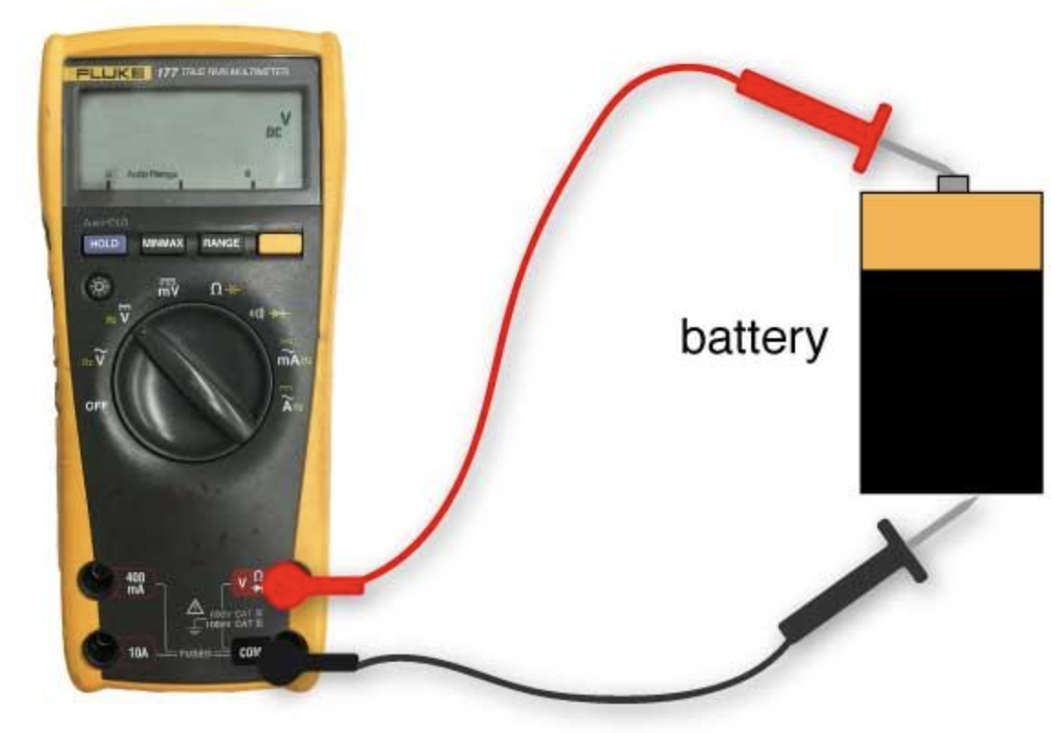
For a DC circuit, the polarity of the leads may affect whether the reading appears positive or negative.
Measuring the Voltage of a Cell
A voltmeter can be connected directly across the terminals of a cell.
If the meter reads:
\[ 1.5\text{ V} \]
the potential difference between the terminals is approximately 1.5 volts.
This means that the source can transfer approximately:
\[ 1.5\text{ J} \]
of electrical energy for every coulomb of charge passing through the source.
Voltage Across Circuit Components
Components transfer electrical energy into other forms.
For example, a lamp converts electrical energy mainly into:
- light energy
- thermal energy
If the voltage across a lamp is:
\[ 6\text{ V} \]
then each coulomb of charge transfers approximately:
\[ 6\text{ J} \]
of electrical energy as it passes through the lamp.
This connection between voltage and energy transfer is one of the most important concepts in circuit physics.
Batteries in Series
Cells can be connected so that their voltages combine.
For example, two 1.5 V cells connected appropriately in series can provide approximately:
\[ 1.5+1.5=3.0\text{ V} \]
Three such cells can provide:
\[ 1.5+1.5+1.5=4.5\text{ V} \]
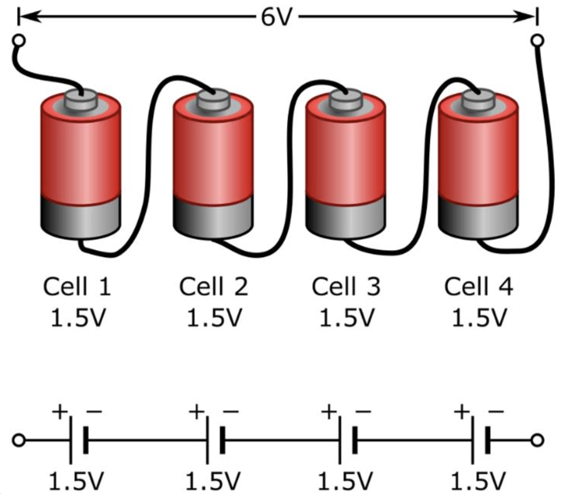
A larger total voltage can produce a larger current if the resistance of the circuit remains unchanged.
Worked Example: Comparing Batteries
Battery A provides:
\[ 3\text{ V} \]
Battery B provides:
\[ 9\text{ V} \]
If each sends 2 C of charge through a component, how much energy can each transfer?
Battery A
\[ E=VQ \]\[ E=3\times2 \]\[ E=6\text{ J} \]
Battery B
\[ E=9\times2 \]\[ E=18\text{ J} \]
Battery B transfers more energy to each amount of charge because it has the greater voltage.
Real-World Voltage Values
Different electrical systems operate at very different voltages.
Examples include:
- individual cells: often around a few volts
- USB-powered electronics: low-voltage DC systems
- vehicle electrical systems: typically higher than individual cells
- household electrical supplies: much higher voltage
- power transmission systems: extremely high voltage
The voltage chosen depends on the purpose of the electrical system.
Higher voltage can allow more energy to be transferred per coulomb of charge, but electrical safety becomes increasingly important as voltage rises.
Voltage and Electrical Safety
Voltage is one factor that affects electrical hazards.
A sufficiently large potential difference can drive harmful current through the human body.
The actual current depends on factors including:
- voltage
- resistance of the body
- skin condition
- path through the body
- duration of contact
For this reason, electrical systems use insulation, grounding, protective devices, and safe operating procedures.
Common Mistakes
Mistake 1: Voltage and current are the same thing
They are different quantities.
Voltage: energy transferred per unit charge.
Current: rate of flow of charge.
Mistake 2: Voltage flows through a wire
Voltage does not flow.
Charge flows, producing current.
Voltage is a potential difference between two points.
Mistake 3: A voltmeter is connected in series
A voltmeter is connected in parallel across the component.
Mistake 4: A battery contains voltage like a container contains water
A battery maintains a potential difference through chemical processes.
Voltage describes a difference between the terminals, not a substance stored inside the battery.
Mistake 5: Higher voltage always means exactly proportional current
For a fixed resistance, increasing voltage increases current proportionally.
However, the resistance of some components can change with temperature or operating conditions.
Mistake 6: Voltage measures the total amount of energy
Voltage measures energy transferred per unit charge, not simply total energy.
Check Your Understanding
1. Define voltage.
2. What is another name for voltage?
3. State the SI unit of voltage.
4. What does a potential difference of 1 V mean?
5. Write the equation relating voltage, energy, and charge.
6. A battery transfers 18 J of energy to 3 C of charge. Calculate the voltage.
7. A charge of 4 C moves through a potential difference of 5 V. Calculate the energy transferred.
8. Explain how a battery creates a potential difference.
9. State one important difference between voltage and current.
10. Which quantity is measured in amperes?
11. Which quantity is measured in volts?
12. Predict what normally happens to current if voltage increases while resistance remains constant.
13. What instrument is used to measure voltage?
14. How should a voltmeter be connected to a lamp?
15. Explain why a voltmeter must be connected across a component rather than simply placed somewhere in series.
16. Two 1.5 V cells are connected appropriately in series. What total voltage do they provide?
17. Explain why saying "voltage flows through the circuit" is scientifically incorrect.
18. Challenge: A resistor has a resistance of \(8\,\Omega\). Calculate the current when the voltage is 4 V and again when the voltage is 12 V. Describe the relationship you observe.
Key Terms
- Voltage – electrical potential difference; the energy transferred per unit charge.
- Potential difference – the difference in electrical potential between two points.
- Volt (V) – the SI unit of voltage.
- Charge (Q) – an electrical quantity measured in coulombs.
- Coulomb (C) – the SI unit of electric charge.
- Electrical energy – energy associated with electric charges and electric circuits.
- Cell – an electrochemical source of electrical potential difference.
- Battery – a source consisting of one or more electrochemical cells.
- Current – the rate of flow of electric charge.
- Resistance – opposition to the movement of electric charge.
- Voltmeter – an instrument used to measure potential difference.
- Parallel connection – a connection across the same two points of a circuit.
Key Takeaways
- Voltage is electrical potential difference.
- Voltage tells us how much energy is transferred per coulomb of charge.
- Voltage is measured in volts (V).
- One volt equals:
\[ \boxed{1\text{ V}=1\text{ J/C}} \]
- Voltage can be calculated using:
\[ \boxed{V=\frac{E}{Q}} \]
- Batteries create voltage through chemical reactions that separate charge and maintain a potential difference.
- Current and voltage are different: current is the rate of charge flow, while voltage is energy transferred per unit charge.
- For a fixed resistance, increasing voltage causes the current to increase.
- Voltage is measured using a voltmeter.
- A voltmeter is connected in parallel across a component.
- Voltage exists between two points; it does not "flow" through the circuit.
- Circuit components transfer electrical energy, and the voltage across them indicates the energy transferred per coulomb of charge.
4. Circuit Components
Learning outcomes
- I can identify common electrical components.
- I can explain the function of resistors, switches, cells, lamps, and fuses.
- I can recognize standard circuit symbols.
- I can distinguish between power sources and loads.
- I can describe how components work together.


5. Building and Drawing Circuits
Learning outcomes
- I can construct simple electrical circuits.
- I can draw schematic diagrams.
- I can identify open and closed circuits.
- I can safely build basic circuits.
- I can troubleshoot simple circuit faults.
From Circuit Diagrams to Real Circuits
An electrical circuit is a complete conducting pathway through which electric charge can move.
Learning about circuit components is only the beginning. We also need to be able to:
- connect components correctly
- represent circuits using standard symbols
- determine whether a circuit is complete
- operate circuits safely
- identify problems when a circuit does not work
A simple circuit might contain:
cell → switch → lamp → connecting wires → back to cell
The arrangement must provide a complete path from one terminal of the power source, through the components, and back to the other terminal.


Constructing a Simple Circuit
Consider a circuit containing:
- one cell
- one lamp
- connecting wires
One wire connects one terminal of the cell to one terminal of the lamp.
A second wire connects the other lamp terminal back to the other terminal of the cell.
The result is a complete conducting path:
cell → lamp → cell
If all the connections are secure and the components are working, the lamp should light.
This is one of the simplest electrical circuits we can construct.
A Circuit Must Form a Complete Loop
A common mistake is to connect only one side of a lamp to a cell.
For example:
cell → wire → lamp
This does not form a complete circuit.
There must also be a conducting path back to the other terminal of the cell.
A complete circuit is therefore a loop.
A useful question when examining any circuit is:
Can I trace one continuous conducting path from one terminal of the source, through the components, and back to the other terminal?
If yes, the circuit may be complete.
If not, the circuit is open.
Open and Closed Circuits
A closed circuit contains a complete conducting path.
Current can flow around the circuit.
A simple example is:
cell → closed switch → lamp → cell
The lamp can operate.
An open circuit contains a break somewhere in the conducting path.
For example:
cell → open switch → gap → lamp → cell
Because the path is incomplete, current cannot continuously flow around that path.


Open Does Not Mean "On"
The language can initially seem confusing.
An open switch means the contacts are separated.
This creates a gap.
Therefore:
open switch → open circuit → no continuous current through that path
A closed switch means the contacts are connected.
Therefore:
closed switch → closed circuit → current can flow
A useful memory aid is:
Closed = connected
Adding a Switch
A switch allows us to control a circuit without disconnecting wires.
Consider:
cell → switch → lamp → cell
Switch Open
The conducting pathway is broken.
Result: lamp off
Switch Closed
The conducting pathway is complete.
Result: lamp on
The switch does not provide the energy. The cell is the power source.
The switch simply controls the pathway.
Circuit Diagrams
Real circuits can become difficult to draw accurately.
Instead of drawing realistic pictures of cells, wires, lamps, and switches, scientists and engineers use schematic diagrams.
A schematic diagram uses standardized symbols to represent components.
This allows us to concentrate on:
- which components are present
- how they are connected
- whether the circuit is complete
rather than what each component physically looks like.


Common Circuit Symbols
You should be able to recognize and draw the symbols for common components.
Wire: a straight line
Cell: two parallel lines of unequal length
Battery: several cell symbols together
Lamp: a circle containing a cross
Resistor: commonly shown as a rectangle in IEC-style diagrams
Open switch: two contacts separated by a gap
Closed switch: contacts connected
Fuse: represented by the appropriate standardized fuse symbol
Circuit symbols should be drawn clearly using straight lines where appropriate.
Drawing a Simple Circuit
Suppose you are asked:
Draw a circuit containing one cell, one switch, and one lamp.
First identify the components:
- cell
- switch
- lamp
Then connect them into a complete loop.
In text, the arrangement can be represented as:
cell → switch → lamp → cell
In your actual schematic diagram, use the proper standard symbols rather than writing the component names.
When the switch is closed, the circuit should contain a continuous path through all three components.
Rules for Clear Circuit Diagrams
A good circuit diagram should be easy for another person to interpret.
When drawing:
- use standard circuit symbols
- use a ruler for straight connecting wires where practical
- make connections clear
- avoid unnecessary crossings
- make sure the circuit forms the intended pathway
- do not draw realistic pictures of components
- keep the diagram simple and organized
A circuit diagram is a model of the electrical connections, not a picture of the physical layout.
The real circuit might look messy while its schematic diagram remains simple.
Physical Position Does Not Have to Match the Diagram
Suppose a lamp is physically located to the left of a cell on your laboratory table.
In the circuit diagram, the lamp might be drawn on the right.
That is fine.
The important information is how the components are electrically connected, not where they physically sit on the table.
This is one of the major advantages of schematic diagrams.
Worked Example: From Description to Circuit
A student is told:
Build a circuit containing a cell, lamp, and switch so that the switch controls the lamp.
A suitable arrangement is:
cell → switch → lamp → cell
Before connecting anything, the student should:
- identify the components
- inspect the wires
- keep the switch open while assembling the circuit
- connect the components into a complete pathway
- check the circuit before closing the switch
Once the circuit has been checked, the switch can be closed.
If the circuit is working correctly, the lamp should light.
Building Circuits Safely
School circuits usually operate at low voltages, but safe procedures are still important.
When building a circuit:
- use only the power sources provided or approved by your teacher
- check that wires and components are not visibly damaged
- keep liquids away from electrical equipment
- avoid touching exposed conductors in circuits where your teacher has told you not to
- open the switch or disconnect the power before changing connections
- do not deliberately create a short circuit
- stop if a component becomes unusually hot
- follow the voltage and current limits of components
- follow your teacher's laboratory instructions
Never experiment with household mains electricity.
Short Circuits
A short circuit occurs when a very low-resistance pathway allows a large current to bypass the intended load.
For example, connecting the terminals of a cell directly together with a wire can create a short circuit.
This can cause:
- large current
- rapid heating
- damaged wires
- damaged cells or batteries
- fire risk in higher-power systems
Therefore:
Never intentionally connect the two terminals of a cell or battery directly together with a wire.
A load or suitable resistance should be included in the circuit.
Why a Lamp Might Not Light
Suppose you build a simple circuit but the lamp does not turn on.
Do not immediately assume the lamp is broken.
There are several possible faults.
The problem might be:
- an open switch
- a loose connection
- a disconnected wire
- a damaged wire
- a flat cell
- a faulty lamp
- incorrect connections
- a component not making electrical contact
Finding the problem systematically is called troubleshooting.
Troubleshooting Circuits
Troubleshooting means identifying and correcting faults in a circuit.
A good troubleshooter works systematically rather than randomly changing components.
Start with the simplest questions.
Is the circuit complete?
Trace the entire path.
source → components → back to source
Look for gaps.
Is the switch closed?
An open switch intentionally breaks the circuit.
Are the wires connected securely?
A wire may appear connected while failing to make good electrical contact.
Is the power source working?
A discharged cell may not provide sufficient potential difference.
Is the lamp working?
Try replacing it with a known working lamp if appropriate.
Are the components connected correctly?
Compare the physical circuit with the intended schematic diagram.
A Simple Troubleshooting Sequence
Imagine this circuit:
cell → switch → lamp → cell
The switch is closed, but the lamp does not light.
A sensible troubleshooting sequence might be:
Check the switch.
Is it actually closed?
↓
Check the connections.
Are all wires securely connected?
↓
Check the cell.
Does it work in another known working circuit?
↓
Check the lamp.
Does another lamp work in its place?
↓
Compare the circuit with the schematic.
Has everything been connected correctly?
This approach changes one thing at a time, making it easier to identify the fault.
Worked Example: The Loose Wire
A student builds a circuit containing:
- one cell
- one switch
- one lamp
The switch is closed, but the lamp is off.
The student notices that one wire is not fully connected to the lamp terminal.
What type of circuit is this?
Open circuit
Even though the switch is closed, the loose wire creates a break in the pathway.
After reconnecting the wire:
the pathway becomes complete → current can flow → lamp operates
This demonstrates an important idea:
A closed switch does not guarantee that the entire circuit is closed.
Every connection must form part of the complete pathway.
Worked Example: The Flat Cell
A circuit appears to be correctly connected.
The switch is closed.
The wires are secure.
The lamp still does not light.
The student replaces the cell with a known working cell.
The lamp now lights.
What was the likely fault?
The original cell was discharged or faulty.
Troubleshooting allowed the student to isolate the problem.
Worked Example: Finding a Fault
Consider a circuit containing:
cell → switch → resistor → lamp → cell
The lamp does not operate.
A student immediately removes every wire and rebuilds the entire circuit.
This may work, but it is not an efficient troubleshooting method because the student may never discover what caused the problem.
A better approach is to:
- inspect the circuit
- compare it with the diagram
- identify possible faults
- test one possibility at a time
Good troubleshooting is systematic.
From a Real Circuit to a Schematic
Sometimes you will be given a physical circuit and asked to draw its schematic.
First identify each component.
For example:
- one cell
- one switch
- two lamps
- connecting wires
Next, follow the wires to determine how the components are connected.
Then replace each physical component with its standard circuit symbol.
Do not try to copy the physical shape of the circuit.
Your diagram should represent the electrical connections.


Predicting Circuit Behaviour
Once you understand the connections, you can predict what will happen.
Consider:
cell → switch → lamp → cell
Switch closed
The path is complete.
Prediction: lamp operates.
Switch open
The path is broken.
Prediction: lamp does not operate.
One wire disconnected
The path is broken.
Prediction: lamp does not operate.
Cell removed
There is no functioning power source and the path is incomplete.
Prediction: lamp does not operate.
Lamp removed from the simple loop
The path is broken.
Prediction: current cannot continuously flow around the circuit.
Circuit Diagrams as Models
A schematic circuit diagram is a type of scientific model.
It leaves out unnecessary details while preserving important information.
For example, a schematic does not normally show:
- the colour of the wires
- the physical size of the cell
- the shape of the laboratory table
- the appearance of the lamp
Instead, it shows:
- components
- connections
- pathways
- circuit structure
This makes circuit diagrams useful for designing, constructing, explaining, and troubleshooting circuits.
Practical Activity: Build, Draw, Break, Fix
This topic works especially well as a short practical investigation.
Build
Construct a simple circuit containing:
- one cell
- one switch
- one lamp
Test the circuit.
Draw
Draw a schematic diagram representing your circuit using standard symbols.
Break
With the power disconnected or switch open, one student introduces one safe fault, such as:
- loosening a wire
- opening the switch
- disconnecting one connection
Do not create a short circuit.
Fix
Another student must:
- inspect the circuit
- identify the fault
- explain why it prevents the circuit from operating
- correct the problem
Then swap roles.
This combines circuit construction, schematic diagrams, open and closed circuits, safety, and troubleshooting in one activity.
Common Mistakes
"If the switch is closed, the circuit must be closed."
Not necessarily.
A loose wire or another break elsewhere can still create an open circuit.
"Electricity only needs a path from the cell to the lamp."
Incorrect.
A simple circuit needs a complete conducting loop back to the power source.
"A circuit diagram should look like the real circuit."
Incorrect.
A schematic shows electrical connections using standardized symbols.
"If the circuit doesn't work, replace everything."
This is poor troubleshooting.
Test possible causes systematically, ideally changing one variable at a time.
"Connecting the battery terminals directly is a quick way to test the battery."
Do not do this.
It can create a short circuit and cause dangerous heating.
"Open switch means the circuit is switched on."
Incorrect.
An open switch creates a gap. A closed switch completes the pathway.
Check Your Understanding
1. What must a simple circuit have before current can continuously flow?
2. What is the difference between an open circuit and a closed circuit?
3. What happens when a switch is opened?
4. What happens when a switch is closed?
5. Why do we use schematic circuit diagrams instead of realistic drawings?
6. Name three rules for drawing a clear circuit diagram.
7. A switch is closed but the lamp does not light. Give three possible faults.
8. Why should you change only one thing at a time when troubleshooting?
9. Why should power normally be disconnected or the switch opened before changing a circuit?
10. What is a short circuit?
11. Why can a short circuit be dangerous?
12. A student has connected one side of a lamp to a cell but has not connected the other side. Is the circuit open or closed? Explain.
13. Why might a schematic diagram look very different from the physical arrangement of the components?
14. Describe a sensible sequence for troubleshooting a lamp that does not light.
Key Terms
- Circuit – a conducting pathway containing electrical components.
- Closed circuit – a circuit containing a complete conducting pathway.
- Open circuit – a circuit containing a break in the conducting pathway.
- Schematic diagram – a simplified diagram using standard symbols to represent circuit components and connections.
- Circuit symbol – a standardized symbol representing an electrical component.
- Switch – a component used to open or close a conducting pathway.
- Power source – a device that supplies energy to a circuit.
- Load – a component that transfers electrical energy into other forms.
- Short circuit – an unintended very low-resistance pathway that can allow dangerously large current.
- Fault – a problem that prevents a circuit from operating as intended.
- Troubleshooting – the systematic process of finding and correcting faults.
- Connection – the electrical link between components.
Key Takeaways
- A simple electrical circuit requires a complete conducting pathway.
- A closed circuit provides a complete path through which current can flow.
- An open circuit contains a break in the pathway.
- Standard circuit symbols are used to create clear schematic diagrams.
- A schematic shows electrical connections, not the physical appearance or position of components.
- Circuits should be constructed using appropriate low-voltage equipment and safe procedures.
- A direct low-resistance connection across a power source can create a dangerous short circuit.
- Circuit faults include loose wires, open switches, faulty components, incorrect connections, and discharged cells.
- Effective troubleshooting involves checking the circuit systematically and changing one thing at a time.
- Being able to build, draw, predict, and troubleshoot circuits are closely connected practical skills.