Rote
6. Applications of Rigid Body Mechanics
Applications of Rigid Body Mechanics
Putting motion, forces, torque and equilibrium together
Rigid-body mechanics connects the ideas from the previous chapters. Engineers and scientists use it to predict how doors, wheels, tools, beams, robotic arms, and vehicles move or balance under forces.
Learning targets
- I can identify rigid-body mechanics in everyday systems.
- I can combine translational and rotational descriptions.
- I can calculate torque and use equilibrium conditions.
- I can interpret the role of moment of inertia and center of mass.
- I can evaluate the limits of simplified physical models.
1. Doors, wrenches and levers
For a hinged door, the turning effect depends on the force, the perpendicular distance from the hinge, and the angle of the push. The same principle makes a long wrench more effective than a short one.
A mechanic applies 80 N perpendicular to a wrench 0.25 m long.
τ = rF = 0.25 × 80 = 20 N·m.
If the wrench is lengthened to 0.40 m and the force remains perpendicular, τ = 0.40 × 80 = 32 N·m.
Increasing the lever arm increases torque without increasing force.
2. Balancing a seesaw
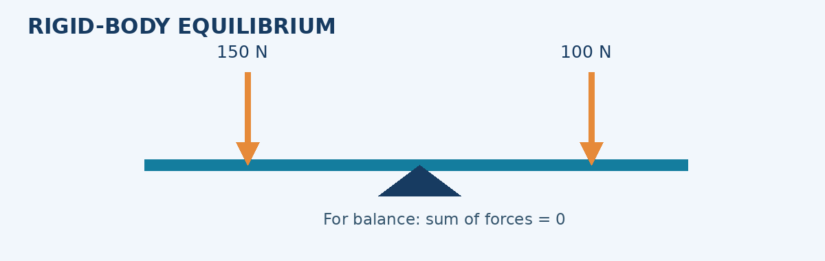
In static equilibrium, clockwise and counterclockwise torques balance around the pivot, and the net force is zero. Choosing the pivot as the torque origin often eliminates the unknown support force from the torque equation.
A child weighing 300 N sits 2.0 m to the left of the pivot. Where should a 400 N child sit on the right to balance?
Set magnitudes of torques equal: 300 × 2.0 = 400 × d.
d = 600/400 = 1.5 m to the right.
The heavier child sits closer to the pivot.
Balancing torque does not automatically establish all equilibrium conditions. For a complete free-body analysis, check the vertical and horizontal forces too.
3. Rolling wheels and vehicle motion
A vehicle wheel combines translation of its center with rotation about the axle. For rolling without slipping, v = Rω. A larger wheel has a lower angular speed at the same road speed.
A bicycle travels at 6 m/s with wheel radius 0.30 m. Assume rolling without slipping.
ω = v/R = 6/0.30 = 20 rad/s.
Revolutions per second = ω/(2π) = 20/(2π) ≈ 3.18 rev/s.
Braking forces create torques on the wheel. Tire-road friction also affects the wheel’s rotation and the vehicle’s translation. If the wheel skids, the rolling condition is invalid.
4. Center of mass and stability
The center of mass is the mass-weighted average position of a body. In a uniform gravitational field, weight can be treated as acting through this point for torque calculations.
An object is less likely to tip when the vertical line through its center of mass stays within its support base. Lowering the center of mass and widening the base generally improve stability.
A 2 kg mass is at x = 0 m and a 4 kg mass at x = 3 m. Neglect the rod’s mass.
xcm = (m₁x₁ + m₂x₂)/(m₁ + m₂).
xcm = (2 × 0 + 4 × 3)/(2 + 4) = 2.0 m.
The center of mass lies closer to the heavier mass.
5. Rotating machinery and moment of inertia
Moment of inertia depends on how mass is distributed relative to the axis. For the same mass and radius, a thin hoop has I = MR² while a uniform solid disk has I = ½MR² about their central axes. The hoop is harder to angularly accelerate with the same torque.
A solid disk and thin hoop each have mass 2 kg and radius 0.50 m.
Disk: I = ½MR² = 0.5 × 2 × 0.50² = 0.25 kg·m².
Hoop: I = MR² = 2 × 0.50² = 0.50 kg·m².
With the same net torque, the disk has twice the angular acceleration.
6. Engineering decisions and model limits
Rigid-body analysis is useful for robotic arms, gear trains, cranes, sports equipment, structures, and mechanisms. Engineers also need to know when bending, vibrations, fatigue, friction, or collisions make the rigid approximation inadequate.
A 0.75 m door is pushed with 24 N perpendicular to its surface. First calculate the torque. Then explain what happens if the force is applied halfway to the hinge, and why pushing along the door instead of perpendicular to it is ineffective.
Solution: τ = 0.75 × 24 = 18 N·m. At half the radius, τ = 0.375 × 24 = 9 N·m. Pushing along the door toward the hinge gives φ ≈ 0°, so sin φ ≈ 0 and torque is approximately zero.
Common mistakes
- Assuming torque depends only on force magnitude.
- Forgetting that static equilibrium requires both force and torque balance.
- Using v = Rω when a wheel is skidding.
- Assuming objects with equal mass have equal moment of inertia.
- Ignoring deformation when analyzing collisions or bending.
Key terms
- Equilibrium: state of zero net force and zero net torque
- Center of mass: mass-weighted average position
- Support base: region over which an object is supported
- Moment of inertia: rotational resistance related to mass distribution
- Rolling without slipping: motion where v of center equals Rω
- Couple: pair of forces producing pure torque
Check your understanding — fully worked answers
- A 50 N force acts perpendicularly 0.20 m from a hinge. Find torque.
Worked answer: τ = 50 × 0.20 = 10 N·m.
- A 200 N load is 1.5 m left of a pivot. Where must a 300 N load be placed right of the pivot to balance?
Worked answer: 200 × 1.5 = 300d; d = 1.0 m.
- A wheel radius 0.25 m rolls at 5 m/s. Find ω.
Worked answer: ω = v/R = 5/0.25 = 20 rad/s.
- Two equal masses lie at x = 0 and x = 4 m. Find center of mass.
Worked answer: xcm = (m×0 + m×4)/(2m) = 2 m.
- Why might a rigid-body model fail for a crash test?
Worked answer: The vehicle deforms significantly; deformation and energy absorption are central to the result.
Key takeaways
- Rigid-body mechanics applies to tools, vehicles, machines and structures.
- Torque depends on force, lever arm and angle.
- Stability, rolling and angular acceleration require careful modeling assumptions.