Advanced Vector Geometry
5. Applications of Vector Geometry
Learning outcomes
- I can solve engineering applications using vectors.
- I can analyse forces in equilibrium.
- I can model motion in two and three dimensions.
- I can solve optimisation problems involving vectors.
- I can communicate vector reasoning clearly.
Applications of Vector Geometry
Introduction to Vector Geometry in Engineering
Vectors are essential mathematical tools in engineering, physics, architecture, robotics, and transportation.
Many real-world problems involve quantities that have both magnitude and direction. Examples include forces acting on a bridge, the velocity of an aircraft, the movement of a robotic arm, and the tension in a cable supporting a structure.
Vector geometry allows these situations to be represented mathematically and analysed systematically.
Engineers use vectors to:
-
Calculate the combined effects of several forces.
-
Determine whether a structure or object is in equilibrium.
-
Model displacement, velocity, and acceleration.
-
Describe motion in two and three dimensions.
-
Calculate moments and rotational effects.
-
Find shortest distances and optimal directions.
-
Minimise forces, travel distances, or energy requirements.
-
Communicate engineering solutions using equations, diagrams, and units.
The central principle is that vector methods transform complex physical situations into mathematical models that can be calculated, verified, and interpreted.


Reviewing Essential Vector Concepts
Before solving engineering applications, it is important to understand the mathematical properties of vectors.
A vector has:
-
Magnitude: Its size or length.
-
Direction: The orientation in which it acts.
In two dimensions, a vector can be written:
A = (Aₓ, Aᵧ)
In three dimensions:
A = (Aₓ, Aᵧ, A_z)
The components describe how much of the vector acts along each coordinate axis.
Magnitude of a Vector
For a two-dimensional vector:
|A| = √(Aₓ² + Aᵧ²)
For a three-dimensional vector:
|A| = √(Aₓ² + Aᵧ² + A_z²)
Worked Example: Magnitude of a Force
A force is represented by:
F = (30, 40) N
Calculate its magnitude.
|F| = √(30² + 40²)
|F| = √(900 + 1600)
|F| = √2500
|F| = 50 N
The force has a magnitude of 50 N.
Unit Vectors
A unit vector has a magnitude of 1.
For a nonzero vector A:
u = A/|A|
Unit vectors are useful because they describe direction independently of magnitude.
For F = (30, 40):
u = (30/50, 40/50)
u = (0.6, 0.8)
Therefore, a force of magnitude 100 N in this direction is:
F = 100(0.6, 0.8)
F = (60, 80) N
Resolving Forces into Components
Engineering forces often act at angles rather than directly along coordinate axes.
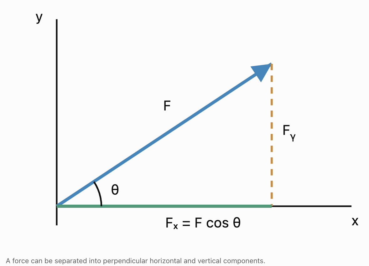
To analyse these forces, they can be resolved into horizontal and vertical components.
For a force F acting at angle θ measured counterclockwise from the positive x-axis:
Fₓ = F cos θ
Fᵧ = F sin θ
The vector is:
F = (F cos θ, F sin θ)
Worked Example: Pulling a Load
A worker pulls a load with a force of 200 N at 30° above the horizontal.
Calculate the horizontal and vertical components.
Step 1: Horizontal component
Fₓ = 200 cos 30°
Fₓ = 200(0.8660)
Fₓ ≈ 173.2 N
Step 2: Vertical component
Fᵧ = 200 sin 30°
Fᵧ = 200(0.5)
Fᵧ = 100 N
Interpretation
The applied force produces:
-
Approximately 173.2 N horizontally.
-
100 N upward.
The upward component reduces the normal force on the load if the load remains on a horizontal surface without other vertical forces.
Important Observation
The horizontal and vertical components are not separate additional forces. They are mathematical representations of the original force.
Resultant Forces
When several forces act on an object, their combined effect is represented by the resultant force.
The resultant is the vector sum:
F_net = F₁ + F₂ + F₃ + ...
For two-dimensional forces:
F_net = (ΣFₓ, ΣFᵧ)
where Σ means the sum of all components.
Worked Example: Three Forces
Three forces act on an object:
F₁ = (40, 20) N
F₂ = (−15, 30) N
F₃ = (−10, −25) N
Calculate the resultant force.
Step 1: Add horizontal components
ΣFₓ = 40 − 15 − 10
ΣFₓ = 15 N
Step 2: Add vertical components
ΣFᵧ = 20 + 30 − 25
ΣFᵧ = 25 N
Step 3: Write the resultant
F_net = (15, 25) N
Step 4: Calculate its magnitude
|F_net| = √(15² + 25²)
= √850
|F_net| ≈ 29.2 N
Step 5: Determine its direction
tan θ = 25/15
θ ≈ 59.0°
Final Answer
The resultant force is approximately:
29.2 N at 59.0° above the positive x-axis.
Forces in Equilibrium
An object is in translational equilibrium when the vector sum of all forces acting on it is zero.
ΣF = 0
In two dimensions:
ΣFₓ = 0
ΣFᵧ = 0
In three dimensions:
ΣFₓ = 0
ΣFᵧ = 0
ΣF_z = 0
An object in translational equilibrium has zero acceleration.
It may be stationary or moving with constant velocity.
Static and Dynamic Equilibrium
-
Static equilibrium: The object remains at rest.
-
Dynamic equilibrium: The object moves with constant velocity.
For a rigid body to be in complete equilibrium, the net torque must also be zero:
Στ = 0
This prevents angular acceleration.
Worked Example: Finding an Equilibrant Force
An object experiences:
F₁ = (50, 20) N
F₂ = (−30, 10) N
Find the third force required for equilibrium.
Step 1: Write the equilibrium condition
F₁ + F₂ + F₃ = 0
Step 2: Rearrange
F₃ = −(F₁ + F₂)
Step 3: Add the known forces
F₁ + F₂ = (50 − 30, 20 + 10)
= (20, 30) N
Step 4: Reverse the resultant
F₃ = (−20, −30) N
Verification
ΣFₓ = 50 − 30 − 20 = 0
ΣFᵧ = 20 + 10 − 30 = 0
The object is in translational equilibrium.
Engineering Application: Cable Tension
Suspended structures often use cables to support loads.
Examples include:
-
Suspension bridges.
-
Cranes.
-
Lighting fixtures.
-
Communication towers.
-
Roof supports.
Cable tensions act along the directions of the cables.


Worked Example: Two Supporting Cables
A 600 N load hangs from two cables.
The left cable makes an angle of 30° above the horizontal.
The right cable makes an angle of 60° above the horizontal.
Find the tensions T₁ and T₂.
Assume the load is stationary and the cables are massless.
Step 1: Identify the forces
Left cable:
T₁ = (−T₁ cos 30°, T₁ sin 30°)
Right cable:
T₂ = (T₂ cos 60°, T₂ sin 60°)
Weight:
W = (0, −600) N
Step 2: Apply horizontal equilibrium
−T₁ cos 30° + T₂ cos 60° = 0
T₂ cos 60° = T₁ cos 30°
T₂(0.5) = T₁(0.8660)
Therefore:
T₂ = 1.732T₁
Step 3: Apply vertical equilibrium
T₁ sin 30° + T₂ sin 60° = 600
0.5T₁ + 0.8660T₂ = 600
Step 4: Substitute
0.5T₁ + 0.8660(1.732T₁) = 600
0.5T₁ + 1.5T₁ = 600
2T₁ = 600
T₁ = 300 N
Step 5: Calculate T₂
T₂ = 1.732(300)
T₂ ≈ 519.6 N
Final Answer
Left cable tension = 300 N
Right cable tension ≈ 519.6 N
Engineering Interpretation
The right cable experiences greater tension because of its orientation.
Cable angle strongly affects the forces experienced by supporting structures.
Engineers must account for these differences when selecting cables and designing attachment points.
Three-Dimensional Force Equilibrium
Many engineering structures cannot be accurately represented using only two dimensions.
For example, a crane may support a load using cables extending in several spatial directions.
Each force must then be represented using three components.
Worked Example: Equilibrium in Three Dimensions
Three forces act on a joint:
F₁ = (100, 50, −20) N
F₂ = (−40, 30, 70) N
F₃ = (−20, −60, −10) N
Find the fourth force required for equilibrium.
Step 1: Add the known forces
ΣFₓ = 100 − 40 − 20 = 40 N
ΣFᵧ = 50 + 30 − 60 = 20 N
ΣF_z = −20 + 70 − 10 = 40 N
Therefore:
F_known = (40, 20, 40) N
Step 2: Find the balancing force
F₄ = −F_known
F₄ = (−40, −20, −40) N
Step 3: Calculate its magnitude
|F₄| = √(40² + 20² + 40²)
= √(1600 + 400 + 1600)
= √3600
|F₄| = 60 N
Final Answer
A force of 60 N in the direction (−40, −20, −40) is required to balance the other forces.
Torque and Rotational Equilibrium
Forces can produce rotation as well as translation.
The rotational effect of a force about a point is called torque or moment.
Torque is calculated using the cross product:
τ = r × F
where:
-
τ is the torque vector.
-
r is the position vector from the pivot to the force application point.
-
F is the applied force.
The magnitude is:
|τ| = |r||F| sin θ
where θ is the angle between r and F.

Worked Example: Torque on a Lever
A 150 N force acts perpendicular to a lever at a distance of 0.40 m from the pivot.
Calculate the torque magnitude.
Step 1: Write the formula
|τ| = |r||F| sin θ
Step 2: Substitute
|τ| = (0.40)(150) sin 90°
Step 3: Calculate
|τ| = 60(1)
|τ| = 60 N·m
Rotational Equilibrium
For an object to have no angular acceleration:
Στ = 0
For a rigid body at rest, both conditions must hold:
ΣF = 0
Στ = 0
Worked Example: Balancing a Beam
A horizontal beam is supported at its centre.
A 200 N downward force acts 2 m to the left of the pivot.
How far to the right must a 100 N downward force act to balance the torques?
Assume the beam's own weight is already balanced.
Step 1: Calculate the left torque magnitude
τ₁ = 200(2)
τ₁ = 400 N·m
Step 2: Write the balancing condition
100d = 400
Step 3: Solve
d = 4 m
Final Answer
The 100 N force must act 4 m to the right of the pivot.
Modelling Motion Using Vectors
Motion can be described using position, displacement, velocity, and acceleration vectors.
Position Vector
The position of an object is:
r(t)
where t represents time.
Displacement Vector
Between times t₁ and t₂:
Δr = r(t₂) − r(t₁)
Average Velocity
v_avg = Δr/Δt
Instantaneous Velocity
v(t) = dr/dt
Instantaneous Acceleration
a(t) = dv/dt
These equations apply to motion in two or three dimensions.
Motion with Constant Velocity
For an object moving with constant velocity:
r(t) = r₀ + vt
where:
-
r₀ is the initial position vector.
-
v is the constant velocity vector.
-
t is elapsed time.
Worked Example: Two-Dimensional Motion
A vehicle begins at:
r₀ = (10, 20) m
Its velocity is:
v = (4, 3) m/s
Find its position after 6 seconds.
Step 1: Write the equation
r(t) = r₀ + vt
Step 2: Substitute
r(6) = (10, 20) + 6(4, 3)
Step 3: Calculate the displacement
6(4, 3) = (24, 18)
Step 4: Find the final position
r(6) = (10 + 24, 20 + 18)
Final Answer
r(6) = (34, 38) m
Calculate the Speed
|v| = √(4² + 3²)
|v| = 5 m/s
The vehicle moves at a constant speed of 5 m/s.
Motion with Constant Acceleration
For constant acceleration:
v(t) = v₀ + at
r(t) = r₀ + v₀t + ½at²
These equations can be applied component by component.
Worked Example: Two-Dimensional Accelerated Motion
An object begins at:
r₀ = (0, 0) m
with initial velocity:
v₀ = (5, 10) m/s
Its constant acceleration is:
a = (2, −4) m/s²
Find its position and velocity after 3 seconds.
Step 1: Calculate velocity
v(3) = (5, 10) + 3(2, −4)
v(3) = (5, 10) + (6, −12)
v(3) = (11, −2) m/s
Step 2: Calculate position
r(3) = (0, 0) + 3(5, 10) + ½(2, −4)(3²)
Step 3: Calculate each term
3(5, 10) = (15, 30)
½(2, −4)(9) = (9, −18)
Step 4: Add the vectors
r(3) = (15, 30) + (9, −18)
Final Answer
r(3) = (24, 12) m
v(3) = (11, −2) m/s
Interpretation
After three seconds, the object is 24 m horizontally and 12 m vertically from its starting position.
Its vertical velocity is negative, indicating downward motion at that instant.
Projectile Motion as a Vector Problem
Projectile motion is a common example of two-dimensional motion.
Ignoring air resistance, a projectile experiences constant downward acceleration due to gravity.
Using upward as the positive y-direction:
a = (0, −g)
where:
g ≈ 9.81 m/s²
The initial velocity can be resolved into:
v₀ = (v₀ cos θ, v₀ sin θ)
The position equations are:
x(t) = x₀ + (v₀ cos θ)t
y(t) = y₀ + (v₀ sin θ)t − ½gt²

Worked Example: Projectile Motion
A ball is launched from ground level at 20 m/s and 30° above the horizontal.
Find its position after 2 seconds.
Assume no air resistance.
Step 1: Calculate the initial velocity components
v₀ₓ = 20 cos 30°
v₀ₓ ≈ 17.32 m/s
v₀ᵧ = 20 sin 30°
v₀ᵧ = 10 m/s
Step 2: Calculate horizontal position
x = 17.32(2)
x ≈ 34.64 m
Step 3: Calculate vertical position
y = 10(2) − ½(9.81)(2²)
y = 20 − 19.62
y = 0.38 m
Final Answer
After 2 seconds, the ball is approximately:
r(2) = (34.64, 0.38) m
The ball is just above its original launch height.
Motion in Three Dimensions
Three-dimensional motion is represented using three coordinate functions.
r(t) = (x(t), y(t), z(t))
Velocity and acceleration are:
v(t) = (dx/dt, dy/dt, dz/dt)
a(t) = (d²x/dt², d²y/dt², d²z/dt²)
Worked Example: Drone Motion
A drone follows the position function:
r(t) = (2t, 3t², 10 + t³)
where position is measured in metres and time in seconds.
Find its position, velocity, and acceleration at t = 2 s.
Step 1: Calculate position
r(2) = (2(2), 3(2²), 10 + 2³)
r(2) = (4, 12, 18) m
Step 2: Differentiate to find velocity
v(t) = (2, 6t, 3t²)
At t = 2:
v(2) = (2, 12, 12) m/s
Step 3: Differentiate to find acceleration
a(t) = (0, 6, 6t)
At t = 2:
a(2) = (0, 6, 12) m/s²
Interpretation
At t = 2 s:
-
The drone is at position (4, 12, 18) m.
-
Its velocity is (2, 12, 12) m/s.
-
Its acceleration is (0, 6, 12) m/s².
The drone is accelerating in both the y- and z-directions.
Relative Velocity
Relative velocity describes the motion of one object as observed from another moving object.
If two objects have velocities v_A and v_B:
v_A relative to B = v_A − v_B
This is useful in:
-
Aircraft navigation.
-
Ship navigation.
-
Vehicle tracking.
-
Robotics.
-
Collision analysis.
Worked Example: Relative Motion
Vehicle A travels with velocity:
v_A = (20, 5) m/s
Vehicle B travels with velocity:
v_B = (12, −3) m/s
Find the velocity of A relative to B.
Step 1: Subtract
v_AB = v_A − v_B
v_AB = (20, 5) − (12, −3)
Step 2: Simplify
v_AB = (8, 8) m/s
Step 3: Calculate magnitude
|v_AB| = √(8² + 8²)
= √128
|v_AB| ≈ 11.31 m/s
Interpretation
From Vehicle B's reference frame, Vehicle A moves at approximately 11.31 m/s in a direction 45° above the positive x-axis.
Engineering Optimisation Using Vectors
Optimisation involves finding the best possible solution under given conditions.
Engineers may want to:
-
Minimise the distance travelled.
-
Minimise cable tension.
-
Maximise the useful component of a force.
-
Minimise energy consumption.
-
Find the closest point on a line or plane.
-
Determine an optimal movement direction.
Vectors provide mathematical methods for solving these problems.
Optimising the Direction of a Force
The dot product describes how much of a force acts along a chosen direction.
For force F and unit direction vector u:
F · u = |F| cos θ
This gives the signed component of F along u.
For a force of fixed magnitude, the component in a desired direction is greatest when the force acts directly along that direction.
Worked Example: Maximising Useful Force
A worker applies a 100 N force to move a cart horizontally.
Compare the horizontal force component when the force acts at:
-
0° above the horizontal.
-
30° above the horizontal.
-
60° above the horizontal.
Use:
Fₓ = F cos θ
|
Angle |
Horizontal component |
|---|---|
|
0° |
100 N |
|
30° |
86.6 N |
|
60° |
50 N |
Conclusion
The horizontal component is greatest when the force acts horizontally.
Maximum horizontal component = 100 N
Engineering Interpretation
If the objective is to maximise the force component along a specified direction, the force should align with that direction.
In real applications, friction, geometry, accessibility, and safety may impose additional constraints.
Optimising Work Done
Work done by a constant force is calculated using the dot product:
W = F · d
where:
-
W is work done.
-
F is the force vector.
-
d is the displacement vector.
Equivalently:
W = |F||d| cos θ
Worked Example
A 50 N force acts on an object that moves 8 m.
Calculate the work done when the force acts at:
-
0° to the displacement.
-
60° to the displacement.
-
90° to the displacement.
Case 1: θ = 0°
W = 50(8) cos 0°
W = 400 J
Case 2: θ = 60°
W = 50(8) cos 60°
W = 200 J
Case 3: θ = 90°
W = 50(8) cos 90°
W = 0 J
Conclusion
For fixed force and displacement magnitudes, work is maximised when the force acts in the same direction as the displacement.
Finding the Shortest Distance to a Line
The shortest distance from a point to a line is measured perpendicular to the line.
Vector projection provides an efficient method for calculating this distance.
Suppose a line is:
r = a + td
and a point P has position vector p.
Construct:
w = p − a
The component of w parallel to the line is:
w_parallel = [(w · d)/(d · d)]d
The perpendicular component is:
w_perp = w − w_parallel
Therefore:
Distance = |w_perp|
Worked Example
Find the shortest distance from:
P = (3, 4)
to the line:
r = (1, 1) + t(2, 0)
Step 1: Find the vector from the line to P
w = (3, 4) − (1, 1)
w = (2, 3)
Step 2: Identify the direction vector
d = (2, 0)
Step 3: Calculate the projection coefficient
(w · d)/(d · d)
= [(2)(2) + (3)(0)]/(2² + 0²)
= 4/4
= 1
Step 4: Calculate the parallel component
w_parallel = 1(2, 0)
w_parallel = (2, 0)
Step 5: Calculate the perpendicular component
w_perp = (2, 3) − (2, 0)
w_perp = (0, 3)
Step 6: Calculate distance
|w_perp| = √(0² + 3²)
Final Answer
Shortest distance = 3 units
The nearest point on the line is (3, 1).
Finding the Closest Point on a Plane
The closest point on a plane lies along a line perpendicular to the plane.
For a plane:
n · r = d
and a point P with position vector p, the closest point q is:
q = p − [(n · p − d)/(n · n)]n
Worked Example
Find the closest point on the plane:
z = 2
to:
P = (3, 4, 7)
The normal vector is:
n = (0, 0, 1)
The plane constant is:
d = 2
Step 1: Calculate the numerator
n · p − d = 7 − 2 = 5
Step 2: Calculate the denominator
n · n = 1
Step 3: Apply the formula
q = (3, 4, 7) − 5(0, 0, 1)
Final Answer
q = (3, 4, 2)
Calculate the Distance
P − q = (0, 0, 5)
Therefore:
Distance = 5 units
Engineering Application
This method can be used to calculate the shortest distance between a moving object and a flat surface.
Optimising Cable Tension
Cable tension depends on the direction of the cable.
Consider a load W supported symmetrically by two cables, each making an angle θ above the horizontal.
If the cables have equal tension T:
2T sin θ = W
Therefore:
T = W/(2 sin θ)
Worked Example
A 1000 N load is supported by two identical cables.
Calculate the tension in each cable when:
-
θ = 30°.
-
θ = 45°.
-
θ = 60°.
|
Cable angle above horizontal |
Tension in each cable |
|---|---|
|
30° |
1000 N |
|
45° |
≈ 707.1 N |
|
60° |
≈ 577.4 N |
Interpretation
As the cables become steeper, the tension required to support the same load decreases.
Within this simplified model, the lowest tension occurs when the cables are vertical.
However, real structures have constraints involving cable placement, available space, connection strength, and structural stability.

Optimising a Travel Route
Vector geometry can also be used to compare possible routes.
Worked Example
A robot must travel from:
A = (0, 0)
to:
B = (6, 8)
Route 1: Move 6 m east, then 8 m north.
Route 2: Move directly from A to B.
Calculate the distance for each route.
Route 1
Distance = 6 + 8
Distance = 14 m
Route 2
Displacement vector:
AB = (6, 8)
Distance = √(6² + 8²)
Distance = √100
Distance = 10 m
Comparison
|
Route |
Distance |
|---|---|
|
East then north |
14 m |
|
Direct route |
10 m |
Conclusion
The direct route is 4 m shorter.
This is the shortest possible route between the two points in unobstructed Euclidean space.
Real-world route optimisation may also require considering obstacles, terrain, speed limits, and energy costs.
Real-World Application: Bridge Engineering
Bridges contain structural members that transmit forces through a framework.
Engineers use vector analysis to calculate forces acting at joints and supports.
For a joint in static equilibrium:
ΣF = 0
For the entire bridge structure, rotational equilibrium must also be satisfied:
Στ = 0

Example: Forces at a Joint
Suppose two horizontal forces act on a bridge joint:
F₁ = (800, 0) N
F₂ = (−500, 0) N
A third force must maintain equilibrium.
F₃ = −(F₁ + F₂)
F₃ = −(300, 0)
F₃ = (−300, 0) N
The third force must act 300 N to the left.
In real truss analysis, engineers calculate member forces using joint equilibrium, structural geometry, and support conditions.
Real-World Application: Robotics and Motion Planning
Robots use vectors to represent position, velocity, acceleration, and forces.
A robotic arm may need to move from one location to another while avoiding obstacles.

Worked Example: Moving a Robotic Tool
A robotic tool begins at:
A = (1, 2, 3) m
Its target is:
B = (5, 6, 6) m
Find the displacement vector and straight-line distance.
Step 1: Calculate displacement
AB = B − A
AB = (5 − 1, 6 − 2, 6 − 3)
AB = (4, 4, 3) m
Step 2: Calculate distance
|AB| = √(4² + 4² + 3²)
= √(16 + 16 + 9)
= √41
|AB| ≈ 6.40 m
Step 3: Calculate the unit direction vector
u = AB/|AB|
u = (4/√41, 4/√41, 3/√41)
Approximately:
u ≈ (0.625, 0.625, 0.469)
Interpretation
The unit vector gives the direction of the shortest straight-line movement from the starting point to the target.
A real robotic arm must also satisfy joint limits, collision constraints, and mechanical requirements.
Real-World Application: Aircraft Navigation
Aircraft velocity is affected by wind.
The aircraft's velocity relative to the ground is:
v_ground = v_aircraft + v_wind
Worked Example
An aircraft travels east at 200 km/h relative to the surrounding air.
The wind blows north at 50 km/h.
Find the ground velocity.
Step 1: Represent the vectors
v_aircraft = (200, 0) km/h
v_wind = (0, 50) km/h
Step 2: Add the vectors
v_ground = (200, 50) km/h
Step 3: Calculate ground speed
|v_ground| = √(200² + 50²)
= √42500
|v_ground| ≈ 206.2 km/h
Step 4: Calculate direction
tan θ = 50/200
θ ≈ 14.0°
Final Answer
Ground speed ≈ 206.2 km/h
Direction ≈ 14.0° north of east
Interpretation
The wind changes both the speed and direction of the aircraft relative to the ground.
Pilots must account for wind when selecting headings.
Real-World Application: Computer Graphics and Engineering Design
Computer-aided design systems use vectors to represent three-dimensional objects.
Vectors can describe:
-
Surface directions.
-
Surface normals.
-
Distances between components.
-
Object movement.
-
Rotational effects.
-
Intersections between geometric surfaces.
The cross product is particularly useful for calculating surface normals.
Given two nonparallel vectors A and B lying in a plane:
n = A × B
The resulting vector is perpendicular to the plane.

Example: Surface Normal
Two vectors lie along a surface:
A = (2, 0, 0)
B = (0, 3, 0)
Calculate a normal vector.
A × B = (0, 0, 6)
Therefore:
n = (0, 0, 6)
The corresponding unit normal is:
u = (0, 0, 1)
This indicates that the surface faces in the positive z-direction according to the chosen vector order.
Communicating Vector Reasoning Clearly
Engineering solutions must be mathematically correct and understandable to other people.
A complete vector solution should communicate:
-
The physical situation.
-
The coordinate system.
-
The known quantities.
-
The assumptions.
-
The relevant vector equations.
-
The calculation steps.
-
The final result with units.
-
The physical meaning of the result.
Example of Clear Mathematical Communication
Problem: Find the force required to balance two forces acting on a joint.
Given:
F₁ = (40, 20) N
F₂ = (−10, 30) N
Method:
For equilibrium:
F₁ + F₂ + F₃ = 0
Therefore:
F₃ = −(F₁ + F₂)
Calculation:
F₁ + F₂ = (30, 50) N
F₃ = (−30, −50) N
Magnitude:
|F₃| = √(30² + 50²)
|F₃| ≈ 58.3 N
Conclusion:
A force of approximately 58.3 N, directed leftward and downward with components (−30, −50) N, is required to maintain translational equilibrium.
Verification:
(40, 20) + (−10, 30) + (−30, −50) = (0, 0)
The equilibrium condition is satisfied.
Why This Format Is Effective
The solution identifies the mathematical principle, shows how it is applied, and verifies the result.
This is the standard of communication expected in technical engineering work.
Multi-Step Engineering Problem: Cable Force and Motion
A 20 kg object is initially stationary.
Two forces act on it:
F₁ = (80, 40) N
F₂ = (−20, 60) N
Assume the forces are constant and these are the only forces included in the model.
Find:
-
The resultant force.
-
The acceleration.
-
The velocity after 3 seconds.
-
The displacement after 3 seconds.
Step 1: Calculate the Resultant Force
F_net = F₁ + F₂
F_net = (80, 40) + (−20, 60)
F_net = (60, 100) N
Step 2: Calculate Acceleration
Newton's Second Law:
F_net = ma
Therefore:
a = F_net/m
Substitute:
a = (60, 100)/20
a = (3, 5) m/s²
Step 3: Calculate Velocity
Since the object begins at rest:
v₀ = (0, 0)
Use:
v = v₀ + at
At t = 3 s:
v = (0, 0) + 3(3, 5)
v = (9, 15) m/s
Step 4: Calculate Displacement
Use:
Δr = v₀t + ½at²
Since v₀ = 0:
Δr = ½(3, 5)(3²)
Δr = 4.5(3, 5)
Δr = (13.5, 22.5) m
Step 5: Calculate Displacement Magnitude
|Δr| = √(13.5² + 22.5²)
= √(182.25 + 506.25)
= √688.5
|Δr| ≈ 26.24 m
Final Answers
-
Resultant force: (60, 100) N
-
Acceleration: (3, 5) m/s²
-
Velocity after 3 s: (9, 15) m/s
-
Displacement after 3 s: (13.5, 22.5) m
-
Displacement magnitude: approximately 26.24 m
Engineering Interpretation
The resultant force causes the object to accelerate in both coordinate directions.
Because the acceleration is constant and the object starts from rest, its velocity and displacement remain in the same direction as the resultant force.
Multi-Step Optimisation Problem: Closest Point on a Path
A robot travels along the line:
r = (1, 2, 0) + t(2, 1, 2)
A target is located at:
P = (5, 5, 4)
Find the point on the robot's path closest to the target.
Step 1: Identify the Line Information
a = (1, 2, 0)
d = (2, 1, 2)
p = (5, 5, 4)
Step 2: Construct the Vector from the Line to the Target
w = p − a
w = (4, 3, 4)
Step 3: Calculate the Closest-Point Parameter
The closest point occurs when:
t = (w · d)/(d · d)
Calculate:
w · d = (4)(2) + (3)(1) + (4)(2)
= 8 + 3 + 8
= 19
d · d = 2² + 1² + 2²
= 4 + 1 + 4
= 9
Therefore:
t = 19/9
Step 4: Calculate the Closest Point
q = a + td
q = (1, 2, 0) + (19/9)(2, 1, 2)
Therefore:
q = (47/9, 37/9, 38/9)
Approximately:
q ≈ (5.22, 4.11, 4.22)
Step 5: Calculate the Minimum Distance
p − q = (−2/9, 8/9, −2/9)
Distance = √[4/81 + 64/81 + 4/81]
Distance = √(72/81)
Distance = 2√2/3 ≈ 0.943 units
Final Answer
The closest point on the robot's path is:
(47/9, 37/9, 38/9)
The minimum distance to the target is:
2√2/3 ≈ 0.943 units
Verification
The shortest connecting vector should be perpendicular to the path direction.
(p − q) · d
= (−2/9)(2) + (8/9)(1) + (−2/9)(2)
= −4/9 + 8/9 − 4/9
= 0
The perpendicularity condition is satisfied.
Choosing the Correct Vector Method
|
Engineering problem |
Appropriate method |
|---|---|
|
Resolve an angled force |
Trigonometric components |
|
Find resultant force |
Vector addition |
|
Determine equilibrium |
ΣF = 0 |
|
Determine rotational equilibrium |
Στ = 0 |
|
Calculate torque |
r × F |
|
Calculate work |
F · d |
|
Find motion at constant velocity |
r = r₀ + vt |
|
Find motion at constant acceleration |
r = r₀ + v₀t + ½at² |
|
Determine relative velocity |
Subtract velocity vectors |
|
Find a direction vector |
Subtract position vectors |
|
Find a unit direction vector |
Divide by magnitude |
|
Find shortest distance to a line |
Vector projection |
|
Find closest point on a plane |
Projection along plane normal |
|
Minimise cable tension |
Equilibrium equations and optimisation |
|
Find surface orientation |
Cross product |
|
Optimise a route |
Compare feasible path lengths |
Common Mistakes
Ignoring the direction of a force
Forces must be added as vectors, not simply as positive magnitudes.
Using incorrect signs for components
A force acting left or downward has negative components in the standard coordinate system.
Confusing sine and cosine
The correct component formula depends on how the angle is measured.
Assuming equilibrium means the object is stationary
An object can move at constant velocity while the net force is zero.
Checking forces but ignoring torque
A rigid body requires both force and torque equilibrium to remain at rest.
Confusing force and acceleration
Acceleration is related to net force through F_net = ma.
Using inconsistent units
All quantities must be expressed in compatible units before calculations.
Confusing position and displacement
Position describes location, while displacement describes a change in location.
Confusing speed and velocity
Speed is scalar; velocity is a vector.
Confusing distance travelled and displacement magnitude
They are equal only when the motion follows an appropriate straight path without reversal.
Ignoring the coordinate system
Directions and signs depend on the chosen coordinate axes.
Assuming all motion occurs in two dimensions
Many engineering problems require three-dimensional models.
Using constant-acceleration equations when acceleration changes
These equations are valid only when acceleration is constant over the interval.
Forgetting that the dot product produces a scalar
The dot product is useful for projections, angles, and work.
Forgetting that the cross product produces a vector
The cross product is useful for torque, normal vectors, and orientation.
Optimising without considering constraints
The mathematically shortest route or lowest-force configuration may not be physically feasible.
Ignoring the physical meaning of a solution
A mathematically correct result must still be checked for reasonableness.
Failing to verify equilibrium
All force components and relevant torque components should sum to zero.
Failing to state assumptions
Engineering models should identify assumptions such as constant acceleration, negligible friction, or massless cables.
Reporting answers without units
Engineering results should include appropriate units and direction information.
Key Terms
-
Vector: A quantity with magnitude and direction.
-
Scalar: A quantity with magnitude but no direction.
-
Vector Component: The amount of a vector acting along a coordinate axis.
-
Resultant Force: The vector sum of all forces acting on an object.
-
Equilibrant Force: A force equal and opposite to the resultant of other forces.
-
Translational Equilibrium: A condition in which the net force is zero.
-
Static Equilibrium: Equilibrium of an object at rest.
-
Dynamic Equilibrium: Equilibrium of an object moving with constant velocity.
-
Rotational Equilibrium: A condition in which the net torque is zero.
-
Torque: The turning effect of a force about a point or axis.
-
Moment Arm: The perpendicular distance from a pivot to a force's line of action.
-
Tension: A pulling force transmitted through a cable, rope, or similar member.
-
Normal Force: A contact force perpendicular to a surface.
-
Weight: The gravitational force acting on an object.
-
Unit Vector: A vector with magnitude 1.
-
Position Vector: A vector describing an object's location.
-
Displacement: The change in position of an object.
-
Velocity: The rate of change of position.
-
Acceleration: The rate of change of velocity.
-
Average Velocity: Displacement divided by elapsed time.
-
Instantaneous Velocity: The derivative of position with respect to time.
-
Relative Velocity: The velocity of one object measured relative to another.
-
Projectile Motion: Motion under gravitational acceleration, usually modelled without air resistance.
-
Dot Product: An operation producing a scalar from two vectors.
-
Cross Product: An operation producing a vector perpendicular to two vectors.
-
Projection: The component of one vector along another direction.
-
Work: Energy transferred by a force acting through a displacement.
-
Angular Momentum: A vector quantity describing rotational motion.
-
Normal Vector: A vector perpendicular to a plane or surface.
-
Optimisation: The process of finding the best solution under specified conditions.
-
Constraint: A restriction that limits possible solutions.
-
Objective Function: A mathematical expression representing the quantity being maximised or minimised.
-
Shortest Distance: The minimum separation between geometric objects.
-
Equilibrium Equation: An equation expressing zero net force or zero net torque.
-
Mathematical Model: A representation of a physical situation using mathematical relationships.
-
Engineering Assumption: A simplification used to make a physical problem mathematically manageable.
-
Verification: Checking that a calculated solution satisfies the original conditions.
-
Dimensional Consistency: The requirement that equations use compatible physical units.
-
Engineering Interpretation: An explanation of what a mathematical result means in a physical system.
Key Takeaways
-
Vectors provide a mathematical framework for solving engineering problems involving forces, motion, geometry, and optimisation.
-
Forces can be resolved into perpendicular components.
-
The resultant force is calculated using vector addition.
-
Translational equilibrium requires the net force to equal zero.
-
Rotational equilibrium requires the net torque to equal zero.
-
Rigid-body equilibrium requires both force and torque equilibrium.
-
Cable tension can be calculated using force components and equilibrium equations.
-
Three-dimensional equilibrium requires balancing forces along all three coordinate axes.
-
Torque is calculated using the cross product of position and force vectors.
-
Position, velocity, and acceleration can be represented using vector functions.
-
Constant-velocity motion is described by r = r₀ + vt.
-
Constant-acceleration motion is described by r = r₀ + v₀t + ½at².
-
Projectile motion can be analysed using horizontal and vertical components.
-
Three-dimensional motion can be represented using vector-valued functions.
-
Relative velocity is calculated by subtracting velocity vectors.
-
The dot product is useful for calculating work, projections, and directional components.
-
The cross product is useful for torque and surface orientation.
-
Vector projection can determine the shortest distance from a point to a line.
-
Plane normals can be used to calculate closest points on planes.
-
Optimisation problems involve maximising or minimising quantities under given constraints.
-
Cable geometry affects the tension required to support a load.
-
The shortest route between two points in unobstructed Euclidean space is a straight line.
-
Engineering applications require correct units, clear assumptions, and verification.
-
The central skill is selecting appropriate vector methods, applying them accurately, and interpreting the results in realistic engineering situations.
Check Your Understanding
Recall and Understanding
-
Explain why vectors are useful for analysing engineering forces.
-
State the conditions required for translational and rotational equilibrium.
-
Describe the difference between position, displacement, velocity, and acceleration.
-
Explain how the dot product and cross product are used in engineering.
-
Describe why constraints must be considered when solving optimisation problems.
Application
-
A 120 N force acts at 40° above the horizontal. Calculate its horizontal and vertical components.
-
Three forces act on a joint: F₁ = (40, 20) N, F₂ = (−15, 30) N, and F₃ = (−10, −25) N. Find the resultant force and its magnitude.
-
Two forces act on an object: F₁ = (60, 20) N and F₂ = (−30, 40) N. Find the third force required for equilibrium.
-
A vehicle begins at position (5, 10) m and moves with constant velocity (3, 4) m/s. Find its position after 8 seconds.
-
A 200 N force acts perpendicular to a lever at a distance of 0.30 m from the pivot. Calculate the torque magnitude.
Analysis and Challenge
-
A 500 N load is supported symmetrically by two cables, each making an angle of 45° above the horizontal. Calculate the tension in each cable.
-
A drone has initial position (2, 3, 5) m, initial velocity (4, 2, 1) m/s, and constant acceleration (1, −2, 3) m/s². Find its position and velocity after 4 seconds.
-
An aircraft travels east at 250 km/h relative to the air while a wind blows north at 60 km/h. Calculate its ground speed and direction.
-
Find the shortest distance from P = (4, 5, 3) to the line r = (1, 1, 1) + t(2, 1, 0).
-
A robotic tool begins at A = (1, 2, 3) and must reach B = (7, 5, 9). Determine the displacement vector, straight-line distance, and unit direction vector. Explain why the direct path may not always be feasible in a real robotic system.
Final Summary
Vector geometry is a fundamental tool for solving engineering problems involving forces, motion, equilibrium, and optimisation.
Forces can be represented as vectors and resolved into components to calculate resultants and determine equilibrium conditions.
Dot products and cross products allow engineers to calculate work, torque, projections, and geometric relationships.
Vector functions provide mathematical models for position, velocity, and acceleration in two and three dimensions.
Optimisation techniques allow engineers to find efficient directions, shortest distances, suitable cable configurations, and improved movement paths.
Real-world engineering problems often combine several of these ideas and require careful attention to physical assumptions, constraints, and units.
Clear communication is also essential. A complete engineering solution should explain the model, show the calculations, verify the results, and interpret their physical significance.
The central principle is that vector geometry connects mathematical reasoning with physical systems, allowing engineers to analyse forces, predict motion, optimise designs, and solve complex problems in two and three dimensions.