Electric Charge and Basic Circuits
2. Electric Current
Learning outcomes
- I can define electric current.
- I can distinguish between conventional current and electron flow.
- I can identify the SI unit of current.
- I can explain how current is measured.
- I can relate current to the movement of charge.
What Is Electric Current?
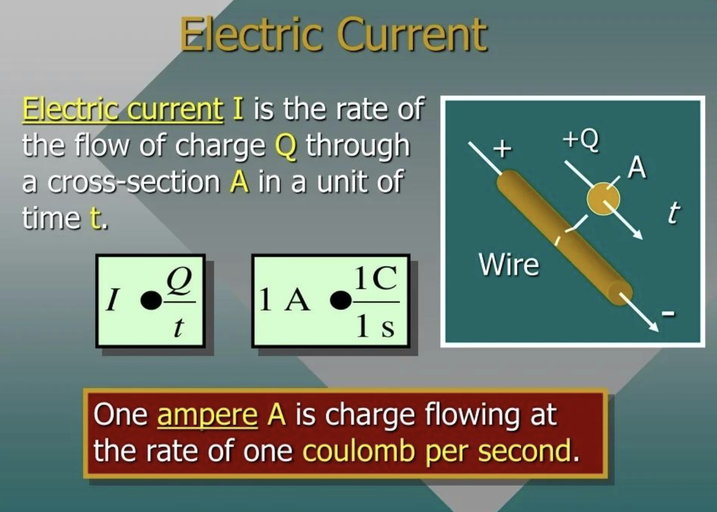
Electric current is the rate at which electric charge flows past a point in a circuit.
In a metal wire, the moving charged particles are electrons. When a complete circuit is connected to a source such as a cell or battery, electrons have a net movement through the conducting wires.
We describe this movement of charge using current.
A useful way to think about it is:
more charge passing each second → larger current
less charge passing each second → smaller current
Current does not tell us how much charge exists in the entire circuit. Instead, it tells us how quickly charge passes a particular point.
Current as a Rate of Flow
Imagine standing beside a road and counting cars.
If 5 cars pass you each minute, the traffic flow is relatively small.
If 100 cars pass you each minute, the traffic flow is much larger.
Electric current is similar, except instead of counting cars, we consider electric charge.
The relationship is:
\[ \boxed{I=\frac{Q}{t}} \]
where:
- \(I\) = electric current
- \(Q\) = electric charge
- \(t\) = time
Current therefore tells us how much charge passes a point per unit time.
The Unit of Electric Current
The SI unit of electric current is the ampere.
Its symbol is:
\[ \boxed{A} \]
The ampere is named after French physicist and mathematician André-Marie Ampère, whose work contributed greatly to our understanding of electricity and magnetism.
In equations, electric current is usually represented by the symbol:
\[ \boxed{I} \]
So we might write:
\[ I=2\text{ A} \]
This means that the electric current is 2 amperes.
What Does One Ampere Mean?
Charge is measured in coulombs (C).
One ampere means that one coulomb of charge passes a point every second.
Therefore:
\[ \boxed{1\text{ A}=1\text{ C/s}} \]
This is an extremely important relationship.
For example:
If 5 C of charge passes a point every second:
\[ I=5\text{ A} \]
If only 0.5 C passes every second:
\[ I=0.5\text{ A} \]
Current is therefore fundamentally a measurement of the rate of movement of electric charge.
Calculating Current
The equation for current is:
\[ I=\frac{Q}{t} \]
Worked Example 1
Suppose 20 C of charge passes through a wire in 5 seconds.
\[ I=\frac{Q}{t} \]
Substitute the values:
\[ I=\frac{20}{5} \]\[ \boxed{I=4\text{ A}} \]
The current is 4 A.
This means charge is passing the point at an average rate of 4 coulombs per second.
Rearranging the Current Equation
The equation:
\[ I=\frac{Q}{t} \]
can also be rearranged.
To calculate charge:
\[ \boxed{Q=It} \]
To calculate time:
\[ \boxed{t=\frac{Q}{I}} \]
So we have three useful forms:
\[ \boxed{I=\frac{Q}{t}} \]\[ \boxed{Q=It} \]\[ \boxed{t=\frac{Q}{I}} \]
Worked Example 2: Finding Charge
A current of 3 A flows for 10 seconds.
How much charge passes through the circuit?
Use:
\[ Q=It \]\[ Q=3\times10 \]\[ \boxed{Q=30\text{ C}} \]
Therefore, 30 coulombs of charge pass through the circuit.
Worked Example 3: Finding Time
A total charge of 24 C passes through a component while the current is 6 A.
How long does this take?
Use:
\[ t=\frac{Q}{I} \]\[ t=\frac{24}{6} \]\[ \boxed{t=4\text{ s}} \]
What Is Actually Moving?
In a metallic conductor, such as a copper wire, the moving charge carriers are electrons.
Metals contain large numbers of mobile or delocalized electrons.
When no electric field is present, these electrons already move randomly through the material.
However, random movement does not produce a net current.
When a source such as a battery establishes an electric field through a complete circuit, the electrons acquire an overall drift direction.
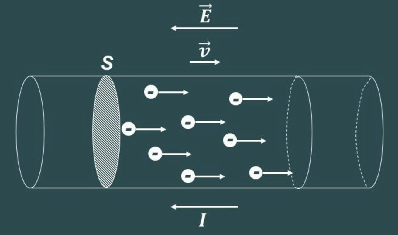
It is this net movement of charge that produces electric current.
Electron Flow
Electrons have a negative charge.
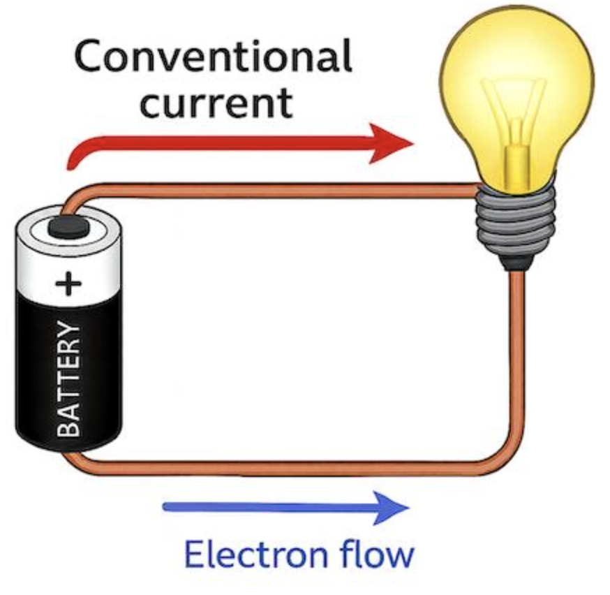
In the external metallic part of a simple DC circuit, their net drift is:
\[ \boxed{\text{negative terminal}\rightarrow\text{positive terminal}} \]
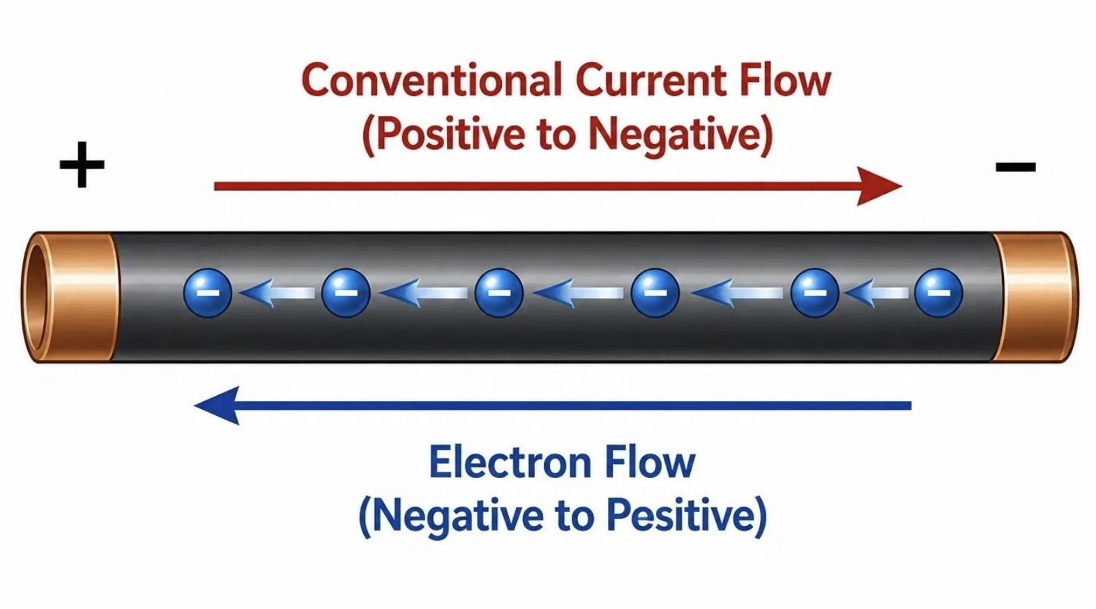
This direction is called electron flow.
However, this creates an important complication.
Circuit diagrams usually show current travelling in the opposite direction.
Conventional Current
Before scientists discovered electrons, they had already chosen a direction to represent electric current.
They assumed that positive charge moved from the positive terminal toward the negative terminal.
This direction became known as conventional current.
Therefore:
Conventional current
\[ \boxed{+\rightarrow-} \]
Electron flow in metallic conductors
\[ \boxed{-\rightarrow+} \]
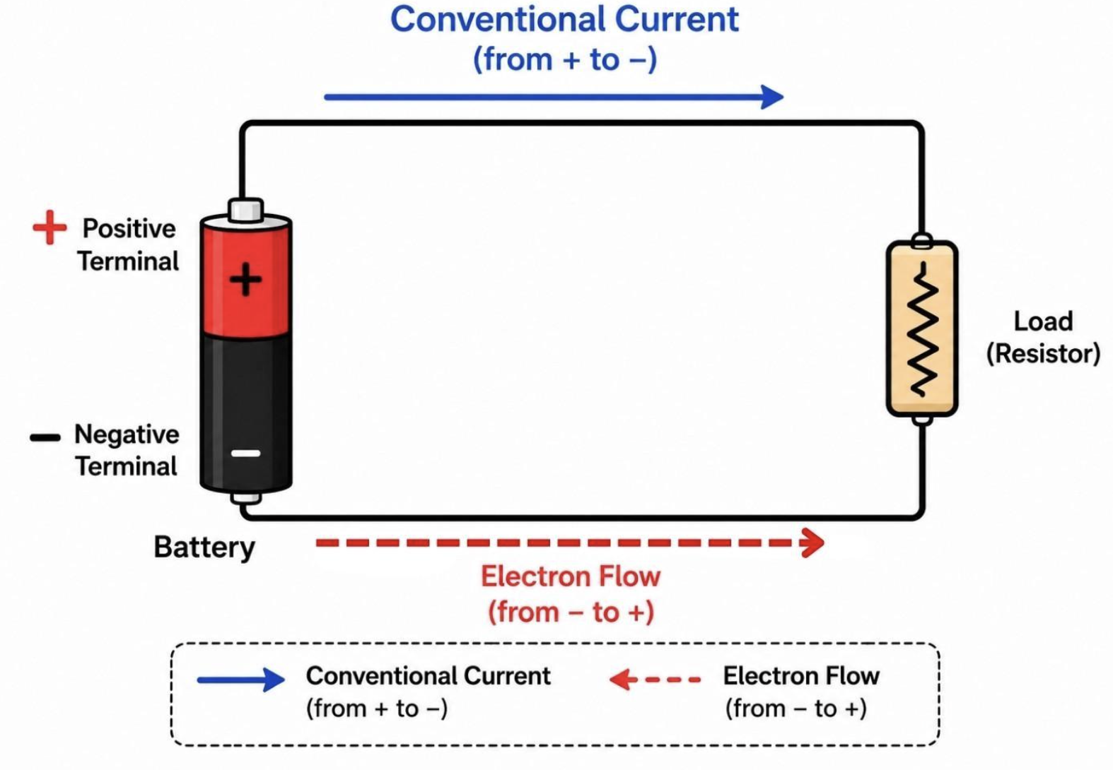
Both directions are useful descriptions, but they refer to different conventions.
In most circuit diagrams and calculations, we use conventional current.
Why Do We Still Use Conventional Current?
It might seem strange to keep using conventional current when we know electrons move in the opposite direction through metal wires.
The reason is largely historical.
Scientists developed many of the rules and symbols of circuit theory before the electron was discovered. By the time scientists understood electron motion, conventional current was already deeply established.
Changing every equation, diagram, textbook, and engineering convention would have created unnecessary confusion.
So conventional current remains the standard.
Remember:
Circuit arrows usually show conventional current.
They do not usually show the direction that electrons drift through a metal wire.
Comparing Electron Flow and Conventional Current
| Electron Flow | Conventional Current |
|---|---|
| Describes movement of electrons in metals | Standard direction used for current |
| Electrons are negatively charged | Treats current direction as movement of positive charge |
| Negative → positive | Positive → negative |
| Describes the actual charge-carrier drift in metallic wires | Used in most circuit diagrams and calculations |
A common mistake is to assume that one direction must be "wrong."
It isn't.
They are simply different ways of describing charge transport.
Measuring Electric Current
Electric current is measured using an instrument called an ammeter.
The circuit symbol for an ammeter is usually shown as:
\[ \boxed{\text{Ⓐ}} \]
An ammeter measures the amount of current flowing through a particular part of a circuit.
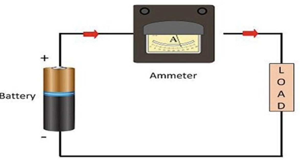
To measure current correctly, the ammeter must be placed so that the current being measured passes through the ammeter.
This means the ammeter is connected in series with the component.
Connecting an Ammeter
Suppose we want to measure the current through a lamp.
The circuit might contain:
cell → ammeter → lamp → cell
The ammeter becomes part of the conducting path.
The current flows through:
- the wire
- the ammeter
- the lamp
- the remaining wire
- back to the source
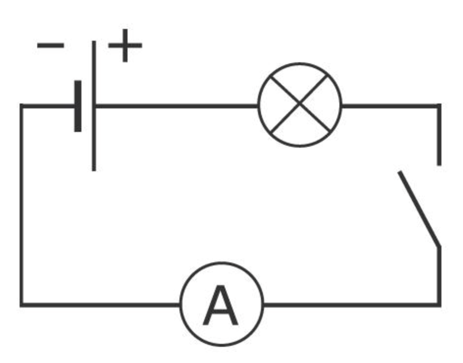
Because the charge passes through the ammeter, the instrument can measure the rate at which charge is flowing.
Ammeters Are Connected in Series
This is one of the most important practical rules when measuring current:
\[ \boxed{\text{An ammeter is connected in series.}} \]
Why?
Because the charge flowing through the component must also flow through the ammeter.
If we want to know the current through a lamp, the ammeter must therefore be placed in the same current path as the lamp.
Later, when we study voltage, we will see that voltmeters are connected differently.
Using a Digital Multimeter
In laboratories, current is often measured using a digital multimeter rather than a dedicated ammeter.
A multimeter can usually measure several electrical quantities, including:
- current
- voltage
- resistance
To measure current, the meter must be placed in the correct current-measuring mode and connected in series with the circuit.
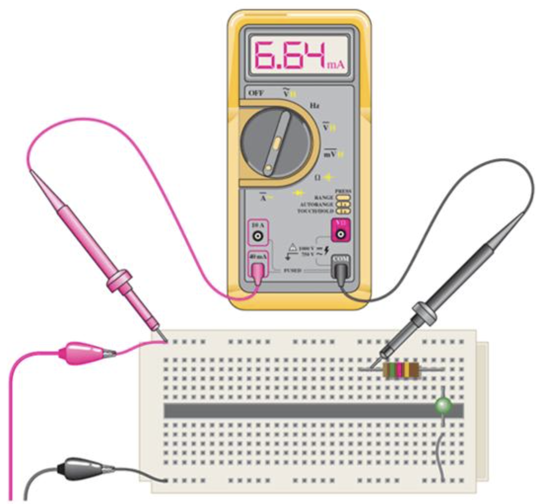
The correct terminals and range must also be selected.
Incorrectly connecting a multimeter while it is set to measure current can create a very low-resistance path, so laboratory instructions and meter ratings should always be followed.
Current in a Simple Series Circuit
Consider a simple circuit containing:
- one cell
- one switch
- one lamp
When the switch is open, the conducting path is incomplete.
There is no sustained current around the circuit.
When the switch is closed, a complete conducting path exists.
Current can then flow.
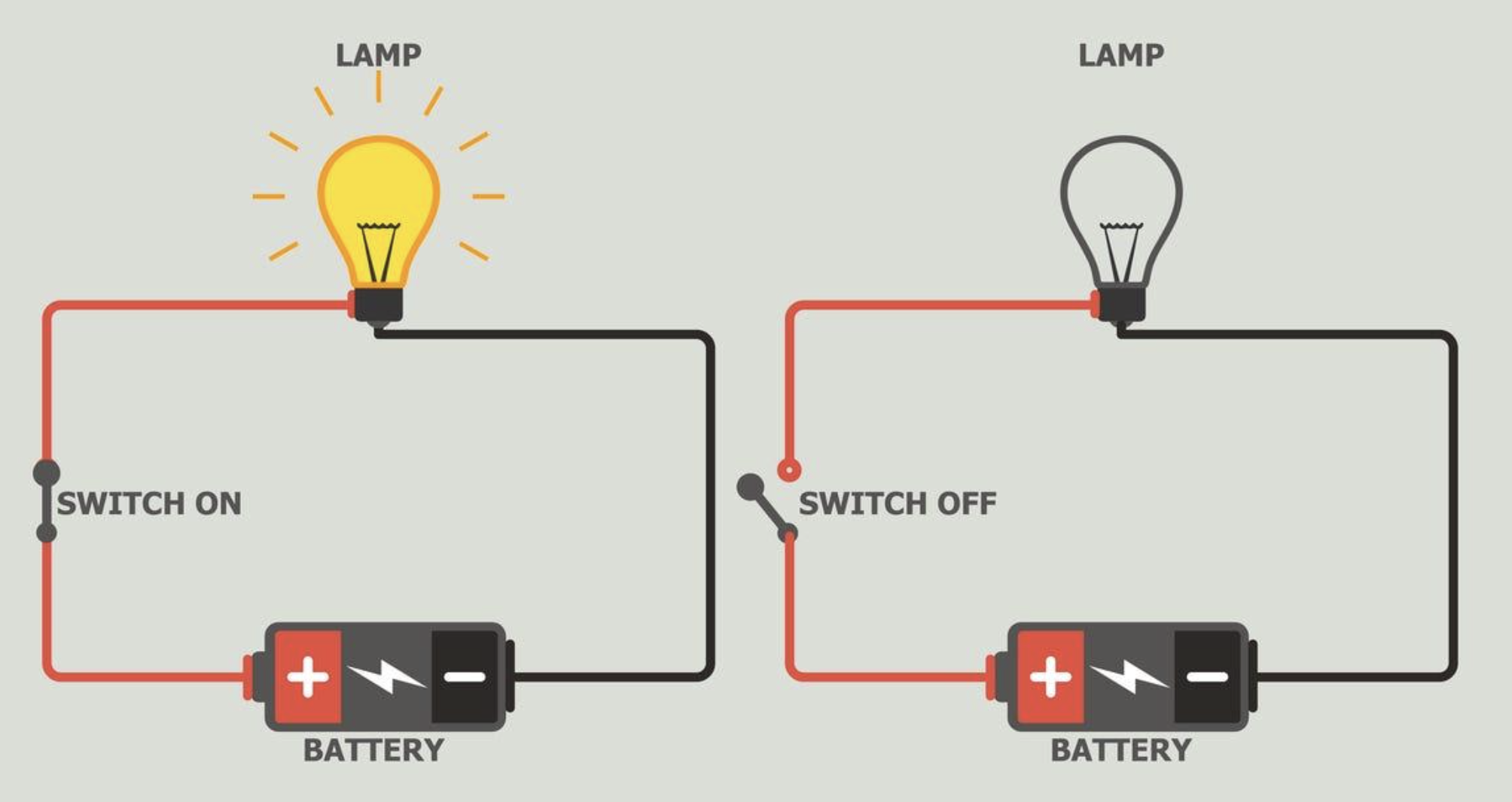
This gives us an important principle:
A sustained current requires a complete conducting path.
Current Is Not "Used Up"
A very common misconception is that a lamp "uses up" current.
It does not.
In a simple series circuit operating steadily, charge does not disappear as it passes through a lamp.
Charge is conserved.
Therefore, the rate of charge flow through one point in a simple series circuit is the same as the rate of charge flow through another point.
Imagine measuring current immediately before and immediately after a lamp.
If:
\[ I_{\text{before}}=0.50\text{ A} \]
then, for a simple steady series circuit:
\[ I_{\text{after}}=0.50\text{ A} \]
The lamp transfers energy, but it does not consume electric charge.
Current and Charge Conservation
Suppose a current of 2 A enters a lamp.
This means:
\[ 2\text{ C} \]
of charge passes into the lamp every second.
If only 1 C per second came out, charge would continuously accumulate inside the lamp.
That does not happen during normal steady operation.
Instead:
\[ 2\text{ C/s enters} \]
and
\[ 2\text{ C/s leaves} \]
Therefore:
\[ I_{\text{in}}=I_{\text{out}} \]
This is another consequence of conservation of charge.
Does a Larger Current Mean Faster Electrons?
This needs careful interpretation.
A larger current means more charge passes a point each second.
That can be related to factors including:
- the number of available charge carriers
- the charge carried by each particle
- their average drift speed
- the cross-sectional area of the conductor
So current is not simply "how fast an electron moves."
Current measures the rate of charge flow.
Large and Small Currents
Not every electrical device operates with the same current.
Very small currents may be measured in:
Milliamperes
\[ 1\text{ mA}=0.001\text{ A} \]
or:
\[ 1000\text{ mA}=1\text{ A} \]
Even smaller currents can be measured in microamperes (μA).
For example:
\[ 1\text{ μA}=0.000001\text{ A} \]
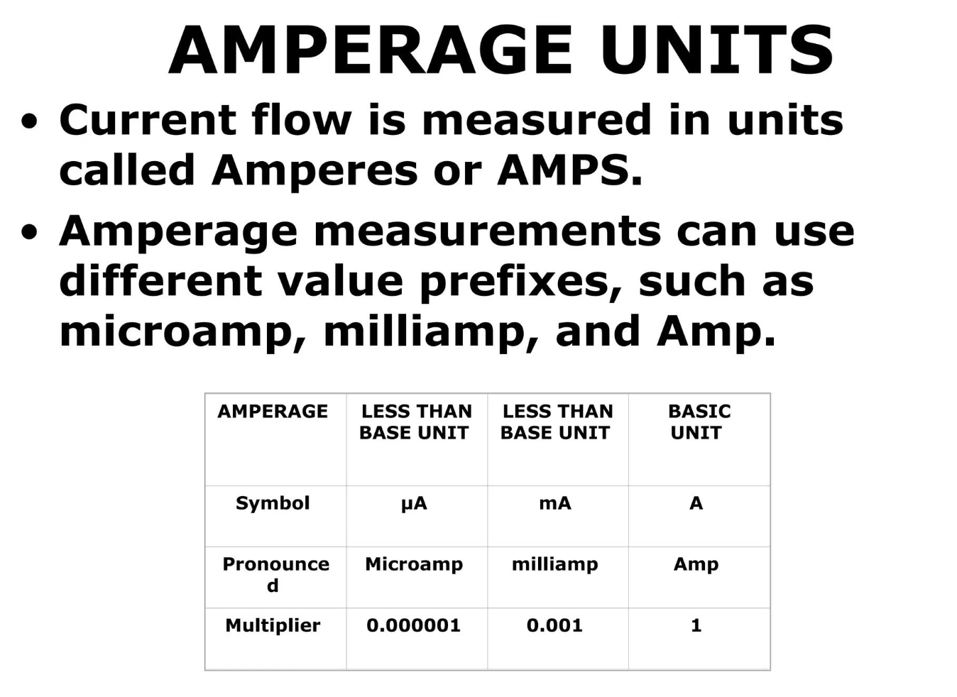
Being comfortable converting between amperes and milliamperes is useful when reading meters and working with electronic circuits.
Worked Example: Milliamperes
A meter reads:
\[ 250\text{ mA} \]
Convert this to amperes.
Because:
\[ 1000\text{ mA}=1\text{ A} \]
divide by 1000:
\[ 250\div1000=0.250 \]
Therefore:
\[ \boxed{250\text{ mA}=0.250\text{ A}} \]
Worked Example: Comparing Currents
Two circuits are measured.
Circuit A
\[ I=0.8\text{ A} \]
Circuit B
\[ I=1.5\text{ A} \]
Circuit B has the larger current.
This means that charge is passing a point at a greater rate in Circuit B.
It does not mean Circuit B contains "more electricity." Current specifically describes the rate of charge flow.
A Useful Analogy: Water Flow
Electric current is sometimes compared with water flowing through a pipe.
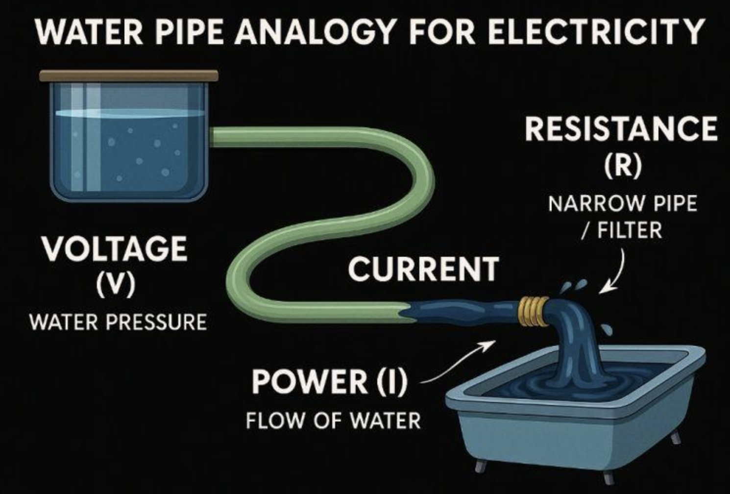
Imagine measuring how much water passes through a pipe every second.
A small flow:
small amount of water per second
A large flow:
large amount of water per second
Similarly:
small current → small amount of charge per second
large current → large amount of charge per second
The analogy is useful for understanding rate of flow, although electric circuits do not behave exactly like water systems.
Real-World Connections
Electric current is important in almost every electrical technology.
Phone Chargers
Chargers are labelled with current ratings, often expressed in amperes.
Household Appliances
Different appliances require different currents depending on their electrical characteristics and operating conditions.
Electronics
Small electronic components may operate with currents measured in milliamperes or even microamperes.
Electric Motors
Electric motors rely on electric current flowing through conductors to produce magnetic effects.
Circuit Protection
Fuses and circuit breakers are designed to respond when current becomes too large for a circuit.
Understanding current is therefore important both for designing circuits and for using electrical systems safely.
Common Mistakes
Mistake 1: Current is the amount of charge
Current is not simply charge.
Current is the rate at which charge flows:
\[ I=\frac{Q}{t} \]
Mistake 2: Current is measured in coulombs
Charge is measured in coulombs (C).
Current is measured in amperes (A).
Mistake 3: Electrons move in the direction of conventional current
In metallic conductors, they move in opposite directions.
Electron flow: − → +
Conventional current: + → −
Mistake 4: An ammeter is connected across a component
An ammeter is normally connected in series so that the current being measured passes through it.
Mistake 5: Components use up current
Components can transfer electrical energy into other forms, but electric charge is conserved.
Current is not gradually "used up" as it travels around a simple series circuit.
Mistake 6: A larger current simply means individual electrons are moving extremely quickly around the circuit
Current measures charge passing per second. Electron drift speed is a related but different concept.
Check Your Understanding
1. Define electric current.
2. What is the SI unit of electric current?
3. What symbol is used for the ampere?
4. What quantity is measured in coulombs?
5. Explain what a current of 1 A means.
6. Calculate the current if 12 C of charge passes a point in 3 seconds.
7. A current of 4 A flows for 5 seconds. Calculate the charge transferred.
8. 30 C of charge passes a point while the current is 5 A. Calculate the time.
9. State the direction of conventional current through the external circuit of a simple cell.
10. State the direction of electron flow through the metallic wires.
11. Explain why conventional current and electron flow point in opposite directions.
12. What instrument is used to measure electric current?
13. How should an ammeter be connected in a circuit?
14. Convert 500 mA into amperes.
15. Convert 0.075 A into milliamperes.
16. Explain why saying that a lamp "uses up current" is incorrect.
17. Circuit A carries 0.4 A and Circuit B carries 1.2 A. What does this tell you about the rates of charge flow?
18. Challenge: A current of 2.5 A flows through a wire for 3 minutes. Calculate the total charge that passes through the wire.
Key Terms
- Electric current – the rate of flow of electric charge.
- Charge – an electrical property of matter measured in coulombs.
- Coulomb (C) – the SI unit of electric charge.
- Ampere (A) – the SI unit of electric current.
- Ammeter – an instrument used to measure electric current.
- Electron flow – the net movement of electrons through a conductor.
- Conventional current – the standard current direction from positive toward negative in an external circuit.
- Drift – the overall directional movement of charge carriers in response to an electric field.
- Series connection – a connection in which components lie along the same current path.
- Milliampere (mA) – one thousandth of an ampere.
- Complete circuit – a continuous conducting path through which sustained current can flow.
Key Takeaways
- Electric current is the rate of flow of electric charge.
- Current is represented by the symbol \(I\).
- The SI unit of current is the ampere (A).
- One ampere means one coulomb of charge passes a point each second:
\[ \boxed{1\text{ A}=1\text{ C/s}} \]
- Current can be calculated using:
\[ \boxed{I=\frac{Q}{t}} \]
- Charge can be calculated using:
\[ \boxed{Q=It} \]
- In metallic conductors, mobile electrons carry charge.
- Electron flow through the external circuit is from negative to positive.
- Conventional current is defined in the opposite direction, from positive to negative.
- Current is measured using an ammeter.
- An ammeter is connected in series with the part of the circuit being measured.
- Current is not "used up" by a circuit component; electric charge is conserved.
- A larger current means more charge passes a point each second.